Advertisement
Quick Links
1. SPECIFICATIONS .............................................................................................................................. 2
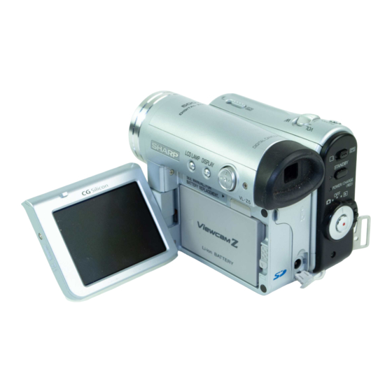
2. PART NAMES .................................................................................................................................... 3
3. DISASSEMBLY OF THE SET ............................................................................................................ 4
4. MECHANISM ADJUSTMENT JIGS AND PARTS .............................................................................. 8
5. INSPECTION AND MAINTENANCE
ITEMS AND INTERVALS ................................................................................................................... 9
6. ADJUSTING AND CHECKING OF MECHANISM ........................................................................... 10
7. ADJUSTMENT OF RUNNING SYSTEM .......................................................................................... 13
8. ASSEMBLING OF MECHANISM SECTION AND PART REPLACEMENT
(DISASSEMBLING AND ASSEMBLING) ........................................................................................... 15
9. METHOD OF ADJUSTING THE ELECTRIC CIRCUIT .................................................................... 25
10.USEFUL TIPS ................................................................................................................................... 43
11.SIGNAL FLOW DIAGRAMS ............................................................................................................. 44
12.BLOCK DIAGRAMS ......................................................................................................................... 47
13.SCHEMATIC DIAGRAMS ................................................................................................................ 54
14.SEMICONDUCTOR LEAD IDENTIFICATION ............................................................................... 120
15.PRINTED WIRING BOARD ASSEMBLIES .................................................................................... 122
16.REPLACEMENT PARTS LIST ....................................................................................................... 139
17.PACKING OF THE SET ................................................................................................................. 161
SHARP CORPORATION
SERVICE MANUAL
LIQUID CRYSTAL DIGITAL CAMCORDER
MODELS
In the interests of user-safety (Required by safety regula-
tions in some countries) the set should be restored to its
original condition and only parts identical to those specified
be used.
CONTENTS
This document has been published to be used for
after sales service only.
The contents are subject to change without notice.
1
1st Edition
VL-Z3S/H/E
VL-Z5S/H/E
VL-Z3S/H/E
VL-Z5S/H/E
S72M7VL-MC500
PAL
Page
Advertisement

Related Manuals for Sharp VL-Z3S


Summary of Contents for Sharp VL-Z3S
- Page 1 VL-Z3S/H/E VL-Z5S/H/E SERVICE MANUAL S72M7VL-MC500 1st Edition LIQUID CRYSTAL DIGITAL CAMCORDER VL-Z3S/H/E VL-Z5S/H/E MODELS In the interests of user-safety (Required by safety regula- tions in some countries) the set should be restored to its original condition and only parts identical to those specified be used.
- Page 2 VL-Z3S/H/E VL-Z5S/H/E 1. SPECIFICATIONS Signal System: PAL standard Recording System: 2 rotary heads, helical scanning system Cassette: Digital VCR Mini DV video cassette Recording/Playback Time: 90 minutes (DVM60, LP mode) Tape Speed: SP mode: 18.831 mm/second LP mode: 12.568 mm/second Pickup Device: "...
- Page 3 VL-Z3S/H/E VL-Z5S/H/E 2. PART NAMES Front view Operation button Zoom lens DISPLAY button LCD LAMP button Stereo microphone Left view Right view Power Zoom Wide angle/ USB terminal Window cleaning cover Telephoto control/ PHOTO button VOLume control Earphones jack (VL-Z5 only)
- Page 4 VL-Z3S/H/E VL-Z5S/H/E 3. DISASSEMBLY OF THE SET 3-1. Procedure for disassembling the cabinet Note: Before removing the cabinet, turn OFF the power and make sure that the battery is not connected. · Remove the lens hood and remove the screw ((s) XiPSF14P06000).
- Page 5 VL-Z3S/H/E VL-Z5S/H/E Mechanism reversion detection PWB unit Camera top cover Connector PWB mounting angle Camera unit FPC(3) FPC(2) FPC(1) · Remove the screw ((x) LX-HZ0050TAFN), screw ((p) LX- · Remove the screw ((b) XiPSN17P03000) and remove the HZ0063TAFN) and screw ((a) XiPSN17P02000), disconnect Mechanism reversion detection PWB unit.
- Page 6 VL-Z3S/H/E VL-Z5S/H/E 3-2. Procedure for disassembling the cabinet · Remove the three screws ((e) XiPSF17P03000) , remove the screw ((d) XiPSF17P02000) and remove the VTR bottom cover. VTR bottom cover · Remove the two screws ((e) XiPSF17P03000) and remove the tilt cover.
- Page 7 VL-Z3S/H/E VL-Z5S/H/E · Disconnect the six FPCs of the head amp circuit board Mechanism unit. · Remove the two screws ((a) XiPSN17P02000) and remove the head amp PWB unit. · Remove the three screws ((w) LX-BZA022WJFN) and remove the screw ((k) LX-BZA023WJFD).