Table of Contents
Advertisement
Quick Links
Advertisement
Table of Contents
Troubleshooting

Related Manuals for Panasonic KX-FP207FX-S


Summary of Contents for Panasonic KX-FP207FX-S
- Page 1 ORDER NO. KMF0609044CE Compact Plain Paper Fax (with Digital Answering System) KX-FP207FX-S KX-FP218FX-S (for Eastern Europe) © 2006 Panasonic Communications Co., Ltd. All rights reserved. Unauthorized copying and distri- bution is a violation of law.
-
Page 2: Table Of Contents
KX-FP207FX-S/FP218FX-S TABLE OF CONTENTS PAGE PAGE 1 Safety Precaution -------------------------------------------------3 15.1. Maintenance Items and Component Locations - 163 1.1. For Service Technicians ----------------------------------3 15.2. Gear Section --------------------------------------------- 165 1.2. AC Caution---------------------------------------------------3 15.3. Jams ------------------------------------------------------- 172 1.3. Personal Safety Precautions ----------------------------4 15.4. -
Page 3: Safety Precaution
KX-FP207FX-S/FP218FX-S 1 Safety Precaution 1. Before servicing, unplug the AC power cord to prevent an electric shock. 2. When replacing parts, use only the manufacturer's recommended components. 3. Check the condition of the power cord. Replace if wear or damage is evident. -
Page 4: Personal Safety Precautions
KX-FP207FX-S/FP218FX-S 1.3. Personal Safety Precautions 1.3.1. Moving Sections of the Unit Be careful not to let your hair, clothes, fingers, accessories, etc., become caught in any moving sections of the unit. The moving sections of the unit are the rollers and a gear. There is a separation roller and a document feed roller which are rotated by the document feed motor. -
Page 5: Service Precautions
KX-FP207FX-S/FP218FX-S 1.4. Service Precautions 1.4.1. Precautions to Prevent Damage from static Electricity Electrical charges accumulate on a person. For instance, clothes rubbing together can damage electric elements or change their electrical characteristics. In order to prevent static electricity, touch a metallic part that is grounded to release the static electricity. -
Page 6: Warning
KX-FP207FX-S/FP218FX-S 2 Warning 2.1. About Lead Free Solder (PbF: Pb free) Note: In the information below, Pb, the symbol for lead in the periodic table of elements, will refer to standard solder or solder that con- tains lead. We will use PbF solder when discussing the lead free solder used in our manufacturing process which is made from Tin, (Sn), Silver, (Ag), and Copper, (Cu). -
Page 7: Insulation Resistance Test
KX-FP207FX-S/FP218FX-S 2.2. Insulation Resistance Test 1. Unplug the power cord and short the two prongs of the plug with a jumper wire. 2. Turn on the power switch. 3. Measure the resistance value with an ohmmeter between the jumpered AC plug and each exposed metal cabinet part (screw heads, control shafts, bottom frame, etc.). -
Page 8: Specifications
KX-FP207FX-S/FP218FX-S 3 Specifications Any details given in these instructions are subject to change without notice. Applicable Lines: Public Switched Telephone Network Document Size: Max. 216 mm in width, Max. 600 mm in length Effective Scanning Width: 208 mm A4: 210 mm × 297 mm... -
Page 9: General/Introduction
Replacement Film (Each roll will print about 90 A4-sized pages) To ensure the unit operates properly, we recommend using the Panasonic replacement film. The ink film is not reusable. Do not rewind and use the ink film again. 5 Features General - For KX-FP218: TAM ring count (feature #06 on P.98) -
Page 10: Technical Descriptions
KX-FP207FX-S/FP218FX-S 6 Technical Descriptions 6.1. Connection Diagram... -
Page 11: General Block Diagram
KX-FP207FX-S/FP218FX-S 6.2. General Block Diagram The following is an outline of each device IC on the digital board. (Refer to General Block Diagram (P.12).). 1. ASIC (IC501) Composed mainly of an address decoder and a modem control. Controls the general FAX operations. - Page 12 KX-FP207FX-S/FP218FX-S 6.2.1. General Block Diagram...
-
Page 13: Control Section
KX-FP207FX-S/FP218FX-S 6.3. Control Section 6.3.1. Block Diagram... - Page 14 KX-FP207FX-S/FP218FX-S 6.3.2. Memory Map...
- Page 15 KX-FP207FX-S/FP218FX-S 6.3.3. ASIC (IC501) This custom IC is used for the general FAX operations. 1. CPU: 6. IMAGE DATA RAM: This model uses a Z80 equivalent to the CPU operating This memory is programmed into the ASIC and uses 8 at 12 MHz.
- Page 16 KX-FP207FX-S/FP218FX-S Descriptions of Pin Distribution (IC501) SIGNAL POWER SUPPLIED DESCRIPTION VOLTAGE VSSA POWER SOURCE (ANALOG GND) VDDA 3.3 3.3V POWER SOURCE (ANALOG +3.3V) AIN1 3.3V CIS IMAGE SIGNAL INPUT (SIG) AIN2 3.3V THERMISTOR TEMPERATURE WATCH INPUT AIN3 3.3V LINE VOLTAGE DETECTION SIGNAL INPUT (DCIN) AMON 3.3V...
- Page 17 KX-FP207FX-S/FP218FX-S SIGNAL POWER SUPPLIED DESCRIPTION VOLTAGE TEST2 3.3V HIGH FIXED TEST3 3.3V HIGH FIXED TEST4 3.3V HIGH FIXED XMDMINT 3.3V MODEM INTERRUPT XMDMCS 3.3V MODEM CHIP SELECT XRAS/IOP 3.3V DRAM (IC503) ROW ADDRESS STROBE XCAS1/IOP 3.3V DRAM (IC503) CULUM ADDRESS STROBE XCAS2/IOP 3.3V...
- Page 18 KX-FP207FX-S/FP218FX-S SIGNAL POWER SUPPLIED DESCRIPTION VOLTAGE XRESETI 3.3V RESET INPUT WDERR 3.3V WATCHED ERROR OUTPUT SIGNAL THDAT 3.3V RECORDED IMAGE OUTPUT (XTHDAT) THCLK 3.3V CLOCK OUTPUT FOR DATA TRANSFER (XTHCLK) THLAT 3.3V PULSE OUTPUT FOR DATA LATCH (XTHLAT) STBNP 3.3V...
- Page 19 KX-FP207FX-S/FP218FX-S 6.3.6. Reset Circuit (Watch dog timer) The output signal (reset) from pin 4 of the voltage detect IC (IC504) is input to the ASIC (IC501) 114 pin. 1. During a momentary power interruption, a positive reset pulse of 50~70 msec is generated and the system is reset com- pletely.
- Page 20 KX-FP207FX-S/FP218FX-S 6.3.7. RTC Backup Circuit 1. Function This unit has a lithium battery (BAT501) which works for Real Time Clock IC (RTC: inside IC501). The RTC continues to work, backed up by a lithium battery even when the power switch is OFF.
- Page 21 KX-FP207FX-S/FP218FX-S 6.3.8. Supervision Circuit for the Terminal Head Temperature 1. Function The thermistor changes the resistor according to the temperature and uses the thermistor's characteristics. The output of pin 139 of IC501 becomes a low level. Then when it becomes a high level, it triggers point A In point C, according to the voltage output time, the thermal head's temperature is detected.
-
Page 22: Facsimile Section
KX-FP207FX-S/FP218FX-S 6.4. Facsimile Section 6.4.1. Image Data Flow During Facsimile Operation Copy (Fine, Super-Fine, Half Tone) 1. Line information is read by CIS (to be used as the reference white level) via route1, and is input to IC501. Refer to Block Dia- gram (P.23) - Page 23 KX-FP207FX-S/FP218FX-S 6.4.2. Block Diagram...
- Page 24 KX-FP207FX-S/FP218FX-S 6.4.3. Thermal Head 1. Function This unit utilizes the state of the art thermal printer technology. The ink film is chemically processed. The ink film is comprised of two parts: an ink layer and a base film. When the thermal- head contacts this ink film, it emits heat momentarily, and the ink layer is melted and transferred to the paper.
- Page 25 KX-FP207FX-S/FP218FX-S...
- Page 26 KX-FP207FX-S/FP218FX-S 6.4.4. Scanning Block The scanning block of this device consists of a control circuit and a contact image sensor made up of a celfoc lens array, an LED array, and photoelectric conversion elements. When an original document is inserted and the start button pressed, pin 34 of IC501 goes to a high level and the transistor Q506 turns on.This applies voltage to the LED array to light it.
- Page 27 KX-FP207FX-S/FP218FX-S 6.4.5. Stepping Motor Drive Circuit 1. Function The stepping motor works for both transmission and reception. 2. Motor During motor driving, pin 124 of ASIC IC501 becomes a high level, and Q403, Q402 turns ON. As a result, +24V is supplied to the motor coil.
- Page 28 KX-FP207FX-S/FP218FX-S When the motor suspends while it is in the receive mode (about 70~80 msec), pin 124 of ASIC IC501 becomes a low level and Q403 turns OFF. Then Q402 also turns OFF, and instead of +24 V, +6 V is supplied through D401 so that the motor is held in place.
-
Page 29: Sensors And Switches
KX-FP207FX-S/FP218FX-S 6.5. Sensors and Switches All of the sensor and switches are shown below. Sensor Circuit Location Sensor Sensor or Switch Name Error Message Operation Panel SW351 Document top sensor [REMOVE DOCUMENT] SW352 Document set sensor [CHECK DOCUMENT] Sensor P.C.Board... - Page 30 KX-FP207FX-S/FP218FX-S 6.5.1. Document Top Sensor (SW351) When a document is brought to the read position, the SW turns ON, and the input signal of IC301-6 pin (Operation Board) becomes a low level. When there is no document at the read position, the SW turns OFF, and the input signal of IC301-6 pin (Operation Board) becomes a high level.
- Page 31 KX-FP207FX-S/FP218FX-S 6.5.3. Paper Top Sensor (SW1001) When the recording paper is loaded on the print head or the recording paper cover is opened, the paper top sensor SW turns ON, and the input signal of IC501-21 pin (Digital Board) becomes a low level. Usually, the SW turns OFF, and the input signal of IC501- 21 pin (Digital Board) becomes a high level.
- Page 32 KX-FP207FX-S/FP218FX-S 6.5.5. Film End Sensor (SW1003) When a film is set, the SW turns ON, and the input signal of IC501-45 pin (Digital Board) becomes a low level. When there is no film, the SW turns OFF, and the input signal of IC501-45 pin (Digital Board) becomes a high level.
-
Page 33: Modem Section
KX-FP207FX-S/FP218FX-S 6.6. Modem Section 6.6.1. Function The unit uses a 1 chip modem (IC505) that serves as an interface between the control section for FAX transmission and recep- tion and the telephone line. During a transmitting operation, the digital image signals are modulated and sent to the telephone line. - Page 34 KX-FP207FX-S/FP218FX-S 3. Facsimile Call Time Series As shown in the following diagram, the facsimile call time series is divided into five phases. Phase A: Call setting Call setting can be manual/automatic. Phase B: Pre-message procedure Phase B is a pre-processing procedure and sequence for confirming the status of the terminal, transmission route, etc., and for terminal control.
- Page 35 KX-FP207FX-S/FP218FX-S 6. Explanation of Communication and Compression Technology a. G3 Communication Signals (T. 30 Binary Process) For G3 Facsimile communication, this is the procedure for exchanging control signals between the sending and receiving machines both before and after transmission of image signals.
- Page 36 KX-FP207FX-S/FP218FX-S Bit No. DIS/DTC Receiver --- T.4 operation Receiver --- T.4 operation 11,12,13,14 Data signaling rate Data signaling rate 0,0,0,0 V.27 ter fall back mode 2400 bit/s, V.27 ter 0,1,0,0 V.27 ter 4800 bit/s, V.27 ter 1,0,0,0 V.29 9600 bit/s, V.29 1,1,0,0 V.27 ter and V.29...
- Page 37 KX-FP207FX-S/FP218FX-S Bit No. DIS/DTC Reserved for future recording width capability. Extend field Extend field R8×15.4 lines/mm R8×15.4 lines/mm 300×300 pels/25.4 mm 300×300 pels/25.4 mm R16×15.4 lines/mm and/or 400×400 pels/25.4 mm R16×15.4 lines/mm and/or 400×400 pels/25.4 mm Inch based resolution preferred Resolution type selection "0": neritic based resolution...
- Page 38 KX-FP207FX-S/FP218FX-S b. Redundancy Compression Process Coding Mode This unit uses one-dimensional MH format.
- Page 39 KX-FP207FX-S/FP218FX-S 6.6.2. Modem Circuit Operation The modem (IC505) has all the hardware satisfying the CCITT standards mentioned previously. When the ASIC IC501 (61) is brought to a low level, the modem (IC505) is chip-selected and the resistors inside IC are selected by the select signals from ASIC (IC501) ADR0-ADR4.
-
Page 40: Ncu Section
KX-FP207FX-S/FP218FX-S 6.7. NCU Section 6.7.1. General NCU is the interface with the telephone line. It is composed of Bell detection circuit, Pulse dial circuit, Line amplifier and sidetone circuits. The following is a brief explanation of each circuit. 6.7.2. EXT. TEL. Line Relay (RL101) 1. - Page 41 KX-FP207FX-S/FP218FX-S 6.7.5. Line Amplifier and Side Tone Circuit 1. Circuit Operation The reception signal output from the line transformer T101 is input to pin (2) of IC101 via C110 and R109 and then the signal is amplified at pin (2) of IC101 and sent to the reception system at 0dB.
- Page 42 KX-FP207FX-S/FP218FX-S 6.7.6. Calling Line Identification Circuit 1. Function This unit is compatible with the Caller ID service offered by your local telephone company. To use this feature, you must sub- scribe to a Caller ID service. The data for the Caller ID from the telephone exchange is sent during the interval between the first and second rings of the bell signal.
-
Page 43: Its
KX-FP207FX-S/FP218FX-S 6.8. ITS (Integrated telephone System) and Monitor Section 6.8.1. General The general ITS operation is performed by the special IC505 which has a handset circuit. The alarm tone, the key tone, and the beep are output from the ASIC IC501 (digital board). During the pulse dial operation, the monitor tone is output from the ASIC IC501. - Page 44 KX-FP207FX-S/FP218FX-S 2. Signal path Refer to Check Sheet for Signal Route (P.123).
-
Page 45: Operation Board Section
KX-FP207FX-S/FP218FX-S 6.9. Operation Board Section The unit consists of a LCD (Liquid crystal display), KEYs and LEDs (light-emitting diodes). They are controlled by the Gate Array (IC301) and ASIC (IC501: on the Digital BOARD). The key matrix table is shown below. -
Page 46: Lcd Section
KX-FP207FX-S/FP218FX-S 6.10. LCD Section The Gate Array (IC301) works only for writing the ASCII code from the data bus (D4~D7). V0 is supplied for the crystal drive. R310, R311, R312 and R314 are density control resistors. Consequently, in this unit, the timing (positive clock) is generated by the LCD interface circuitry in the gate array (IC301). -
Page 47: Power Supply Board Section
KX-FP207FX-S/FP218FX-S 6.11. Power Supply Board Section This power supply board uses the switching regulator method. Block Diagram Input Input Rectifier Circuit C106 Output Circuit Surge Circuit D110 Absorber Converter Circuit Circuit R104 A-B Voltage Wave Form Q101 Kick-on Surge 9~6V... - Page 48 KX-FP207FX-S/FP218FX-S The following is an overview of how the power supply unit is controlled. The control method of this power supply unit is pulse width modulation. When Q is ON, the energy is charged in the transfer primary coil according to E .
- Page 49 KX-FP207FX-S/FP218FX-S [Surge Absorber Circuit] This circuit is for absorbing surge voltage generated by the transformer. [Control Circuit and Detecting Circuit] The control circuit amplifies the output with increased voltage detected in the error detecting circuit. Then it drives the main tran- sistor.
-
Page 50: Location Of Controls And Components
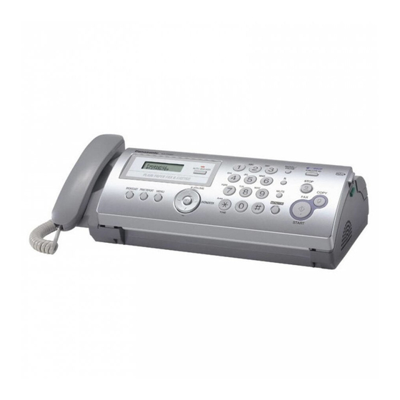
KX-FP207FX-S/FP218FX-S 7 Location of Controls and Components 7.1. Overview 7.2. Control Panel (1) [MIC] (Microphone) (KX-FP218 only) • The built-in microphone. (2) [GREETING REC] (KX-FP218 only) • To record a greeting message. (3) [GREETING CHECK] (KX-FP218 only) • To check a greeting message. -
Page 51: Installation Instructions
KX-FP207FX-S/FP218FX-S 8 Installation Instructions (17) [TONE] • To change from pulse to tone temporarily during dialling when your line has rotary pulse service. 8.1. Installation Space You can also use tone dial service by changing feature #13. The space required to install the unit is shown below. -
Page 52: Connections
KX-FP207FX-S/FP218FX-S 8.2. Connections • If you use the unit with a computer and your internet provider instructs you to install a filter ( ), please connect it as fol- Caution: lows. • When you operate this product, the power outlet should be near the product and easily accessible. -
Page 53: Installing The Ink Film
KX-FP207FX-S/FP218FX-S 8.3. Installing the Ink Film 1. Open the front cover. • Make sure the blue gear ( ) and white gear ( ) are installed as shown. 2. Release the back cover by pushing the green button ( 5. Turn the blue gear (... -
Page 54: Installing The Paper Tray
KX-FP207FX-S/FP218FX-S 8.4. Installing the Paper Tray Pull up the metal recording paper guide ( ), then install the paper tray ( • Make sure the arrows on the paper tray and the unit match. 6. Close the back cover securely by pushing down on the dotted area at both ends ( 7. -
Page 55: Paper Support
KX-FP207FX-S/FP218FX-S 8.5. Paper Support 8.6. Installing the Recording Paper Hold open the paper support ( ), then insert the ends into the The unit can hold up to 20 sheets of 64 g/m to 80 g/m paper. 1. Fan the paper to prevent paper jams. -
Page 56: Operation Instructions
KX-FP207FX-S/FP218FX-S 9 Operation Instructions Document requirements 9.1. Setting Your Logo You can program your logo (name, company name, etc.) so that it appears on the top of each page sent. 1. [MENU] → [#][0][2] → [SET] 2. Enter your logo, up to 30 characters. See the following character table for details. - Page 57 KX-FP207FX-S/FP218FX-S To enter your logo Example: “BILL“ 1. Press [2] 2 times. 2. Press [4] 3 times. 3. Press [5] 3 times. 4. Press [ ] to move the cursor to the next space and press [5] 3 times. To switch between uppercase or lowercase letters...
-
Page 58: Test Mode
KX-FP207FX-S/FP218FX-S 10 Test Mode The codes listed below can be used to perform simple checks for some of the unit’s functions. When complaints are received from customers, they provide an effective tool for identifying the locations and causes of malfunctions. To do this, you set the Service mode (Refer to Operation Flow (P.62).) first, then operate the below test items. -
Page 59: Dtmf Signal Tone Transmit Selection
KX-FP207FX-S/FP218FX-S Test Mode Type of Mode Code Function Operation after code input SENSOR CHECK & Service Mode “8” “1” “5” If you enter this mode and operate sensor levers with your hands, the LCD dis- VOX CHECK play of the related sensor (or switch) turns ON / OFF. Also, when copying a docu- ment, the related sensor will turn ON / OFF. -
Page 60: Button Code Table
KX-FP207FX-S/FP218FX-S 10.2. Button Code Table Code Button Name Code Code Button Name NO INPUT STOP MENU FAX START PRINT REPORT COPY [+] VOLUME MONITOR (FP207) [—] VOLUME SP-PHONE (FP218) BROADCAST MUTE AUTO ANSWER MEMO CHECK REDIAL / PAUSE ERASE PLAYBACK... -
Page 61: Print Test Pattern
KX-FP207FX-S/FP218FX-S 10.3. Print Test Pattern 1. Platen roller 3. Thermal head 1 dot 2. Left margin / Top margin 4. Use this test pattern to confirm the torque limiter for Ink film and platen roller timing. -
Page 62: Service Mode
KX-FP207FX-S/FP218FX-S 11 Service Mode The programming functions are used to program the various features and functions of the machine, and to test the machine. This facilitates communication between the user and the service man while programming the unit. 11.1. Programing and Lists 11.1.1. - Page 63 KX-FP207FX-S/FP218FX-S 11.1.3. Service Function Table Code Function Set Value Effective Default Remarks Range Pause time set X 100 msec 001~600 ---------- Dial speed select 1: 10 pps 1, 2 ---------- 2: 20 pps VOX time (KX-FP218) 1:8sec ---------- 2:6sec 3:4sec...
- Page 64 KX-FP207FX-S/FP218FX-S Code Function Set Value Effective Default Remarks Range TAM continuous tone detection (KX- 1:ON 2:OFF 1, 2 ON : Stops TAM operation when Dial tone, etc. are FP218) detected. FAX auto redial time set X number of 00~99 Selects the number of redial times during FAX commu- times nication (not including the first dial).
- Page 65 KX-FP207FX-S/FP218FX-S Code Function Set Value Effective Default Remarks Range Digital SP-phone check (KX-FP218) See Digital Speakerphone (KX-FP218) (P.126). Print test pattern See Test Mode (P.58). Top margin ---------- Paper size 1:A4 1, 2 ---------- 2:LETTER DTMF ON time X 10 msec...
- Page 66 KX-FP207FX-S/FP218FX-S 11.1.4. Memory Clear Specification Execute Service Mode #550 when you want to reset the all setting data keeping the user information. Execute Service Mode #710 to clear the user information in case that Main Unit is recycled. Note: • Please restart a power supply after clearing a memory.
-
Page 67: The Example Of The Printed List
KX-FP207FX-S/FP218FX-S 11.2. The Example of the Printed List 11.2.1. User Mode 11.2.1.1. KX-FP207FX-S... - Page 68 KX-FP207FX-S/FP218FX-S 11.2.1.2. KX-FP218FX-S Note: The above values are the default values.
- Page 69 KX-FP207FX-S/FP218FX-S 11.2.2. Service Mode Settings 11.2.2.1. KX-FP207FX-S 11.2.2.2. KX-FP218FX-S Note: The above values are the default values.
- Page 70 KX-FP207FX-S/FP218FX-S 11.2.3. History Note: See the following descriptions of this report. Item No. (1) ~ (44) are corresponding to the listed items in Descriptions of the History Report (P.71).
- Page 71 KX-FP207FX-S/FP218FX-S 11.2.3.1. Descriptions of the History Report (1) SOFTWARE VERSION (22) NUMBER OF RECEIVE FLASH ROM version The number of pages received. (2) SUM (23) NUMBER OF SENDING FLASH ROM internal data calculation. The number of pages sent. (3) YOUR LOGO (24) NUMBER OF CALLER ID The user logo recorded in the unit.
-
Page 72: Troubleshooting Guide
KX-FP207FX-S/FP218FX-S 12 Troubleshooting Guide 12.1. Troubleshooting Summary After confirming the problem by asking the user, troubleshoot according to the instructions and observe the following precautions. 12.1.1. Precautions 1. If there is a problem with the print quality or the paper feed, first check if the installation space and the print paper meets the specifications, the paper selection lever/paper thickness lever is set correctly, and the paper is set correctly without any slack. -
Page 73: Error Messages-Display
KX-FP207FX-S/FP218FX-S 12.2. Error Messages-Display If the unit detects a problem, one or more of the following messages will appear on the display. The explanations given in the [ ] are for servicemen only. • The back cover is open. Close the back cover firmly. - Page 74 —Use the overseas transmission mode (feature #23 on Pro- gram Mode Table (P.98)). —Add 2 pauses at the end of the telephone number or dial • Please use genuine Panasonic replacement film. manually. (Refer to Optional Accessories (P.9).) • The ink film is slack. Tighten it (See step 5 on Installing the Ink Film (P.53)).
-
Page 75: Error Messages-Report
KX-FP207FX-S/FP218FX-S 12.3. Error Messages-Report If a problem occurs during fax transmission or reception, one of the following messages will be printed on the sending and jour- nal reports. 12.3.1. Journal Report 1. Press [PRINT REPORT] repeatedly to display “PRINT REPORT”. - Page 76 KX-FP207FX-S/FP218FX-S Countermeasure...
- Page 77 KX-FP207FX-S/FP218FX-S REFERENCE: Test Mode (P.58)
- Page 78 KX-FP207FX-S/FP218FX-S REFERENCE: Test Mode (P.58)
- Page 79 KX-FP207FX-S/FP218FX-S REFERENCE: Test Mode (P.58)
- Page 80 KX-FP207FX-S/FP218FX-S REFERENCE: Test Mode (P.58)
- Page 81 KX-FP207FX-S/FP218FX-S...
- Page 82 KX-FP207FX-S/FP218FX-S...
- Page 83 KX-FP207FX-S/FP218FX-S REFERENCE: Test Mode (P.58)
- Page 84 KX-FP207FX-S/FP218FX-S 12.3.2. Special Service Journal Report Journal 2 and Journal 3 shown below, which are special journals giving the additional detailed information about the latest 35 communications, can be printed by Service Code 881 or 882. Remote printing function for the journal reports (JOURNAL, JOURNAL 2 and JOURNAL 3) is also available for service technicians.
- Page 85 KX-FP207FX-S/FP218FX-S 12.3.2.1. Journal 2 Refer to JOURNAL 2 in Printout Example (P.86). Journal 2 displays the additional detailed information about the last 35 communications. Descriptions: (1) RCV. MODE Indicates which receive mode the unit was in when the unit received a fax message.
- Page 86 KX-FP207FX-S/FP218FX-S 12.3.2.2. Journal 3 Refer to JOURNAL 3 in Printout Example (P.86). Descriptions: (6) ENCODE (9) ERROR LINE(RX) Compression Code: MH/MR When an error occurs while receiving a fax, this shows the number of error lines. (7) MSLT MSLT means Minimum Scan Line Time. Used only at the (10) MAKER CODE factory.
- Page 87 KX-FP207FX-S/FP218FX-S...
- Page 88 KX-FP207FX-S/FP218FX-S 12.3.3. Communication Section Find the problem in the table shown below, and refer to the corresponding troubleshooting procedure in Defective Facsimile Section (P.89). Symptom Reference Content Possible cause 1 The paper is not fed properly when faxing. Transmit Problem (P.89) Problem with the feeding mecha- (Not in the copy mode.)
- Page 89 KX-FP207FX-S/FP218FX-S 12.3.3.1. Defective Facsimile Section 12.3.3.1.1. Transmit Problem REFERENCE: (*1): Operation Panel Section (P.131) (*2): ADF (Auto Document Feed) Section (P.103) (*3): Maintenace (P.163) (*4): How to Remove the Gear Block and Separation Roller (P.146) (*5): How to Remove the Operation Board and LCD (P.155)
- Page 90 KX-FP207FX-S/FP218FX-S 12.3.3.1.2. Sometime there is a transmit problem Note: "596: Transmit level set" represents a service code. (Refer to Service Function Table(P.63).)
- Page 91 KX-FP207FX-S/FP218FX-S 12.3.3.1.3. Receive Problem First confirm whether the recording paper is installed properly or not before starting troubleshooting. (Refer to "Remarks".) Note: • "596: Transmit level set" represents a service code. (Refer to Service Function Table (P.63).) • #06 : Refer to for Program Mode Table (P.98) Fax ring count.
- Page 92 KX-FP207FX-S/FP218FX-S 12.3.3.1.4. The unit can copy, but cannot transmit / receive REFERENCE: (*1): Test Mode (P.58) (*2): Analog Board Section (P.123)
- Page 93 KX-FP207FX-S/FP218FX-S 12.3.3.1.5. The unit can copy, but cannot either transmit/receive long distance or interna- tional communications The following two causes can be considered for this symptom. Cause 1: The other party is executing automatic dialling, the call has been received by this unit, and the CED or DIS signal response time is too long.
- Page 94 KX-FP207FX-S/FP218FX-S (Causes and Countermeasures) Countermeasure Side Echo Communication Problem Example Countermeasure Service Code Sending side Some time is needed to compare the level Add a dummy signal to the beginning of Service code (521) of the receiving and sending signals for the the training signal.
- Page 95 KX-FP207FX-S/FP218FX-S Fig. c (Countermeasure by Changing the Interval Between CED and DIS) Fig. d (Countermeasure by Ignoring the 1st DIS) <TX side signal> <RX side signal> <Countermeasure> 2nd / 3rd DCS / Training & delayed CFR / FTT at TX side 2nd / 3rd EOP / EOM / MPS &...
- Page 96 KX-FP207FX-S/FP218FX-S 12.3.3.1.7. How to record fax signal by using PC Recording FAX signal is one of the useful analysis measures to solve communication problems. The way of recording easily by using PC is shown as follows. 1. Equipment Parts No.
-
Page 97: Remote Programming
KX-FP207FX-S/FP218FX-S 12.4. Remote Programming If, after the call is connected, the customer describes the situation and it is determined that the problem can be corrected by making parameter changes, this function makes it possible to change parameters such as the user code and service code from another fax (using DTMF tones). - Page 98 KX-FP207FX-S/FP218FX-S 12.4.2. Program Mode Table Code Function Set Value Default Remote Set- ting Set date and time dd/mm/yy hh:mm 01/Jan/2006 Your logo --------- None Your FAX number --------- None Print sending report 1:ERROR / 2:ON / 3:OFF ERROR FAX ring count...
- Page 99 KX-FP207FX-S/FP218FX-S Code Function Set Value Default Remote Set- ting Break % select 1:61% 2:67% ITS auto redial time set 00~99 ITS auto redial line disconnection time set 001~999sec 040sec Remote turn-on ring number (KX-FP207) 00~99 Remote turn-on ring number (KX-FP218)
-
Page 100: Troubleshooting Details
KX-FP207FX-S/FP218FX-S 12.5. Troubleshooting Details 12.5.1. Outline Troubleshooting is for recovering quality and reliability by determining the broken component and replacing, adjusting or clean- ing it as required. First, determine the problem then decide the troubleshooting method. If you have difficulty finding the broken part, determine which board is broken. - Page 101 KX-FP207FX-S/FP218FX-S 12.5.3. Troubleshooting Items Table ITEM SYMPTOM REFERENCE The document does not feed. No Document Feed P.103 (Auto Document Feeder) Document jam Document Jam P.104 Multiple feed Multiple Document Feed P.105 Skew Document Skew P.106 Recording paper feed The recording paper does not feed.
- Page 102 KX-FP207FX-S/FP218FX-S 12.5.3.1. Simple Check List SERIAL NO. DATE FUNCTION JUDGEMENT REFERENCE FAX operation Transmission OK / NG Receiving OK / NG Copy operation OK / NG Telephone operation Handset transceiver / receiver OK / NG MONITOR OK / NG Ringer sound...
- Page 103 KX-FP207FX-S/FP218FX-S 12.5.4. ADF (Auto Document Feed) Section 12.5.4.1. No Document Feed REFERENCE: (*1): How to Remove the Separation Holder and Exit Roller (P.157) (*2): Installation Position of the Lead Wires (P.158) (*3): How to Remove the Gear Block and Separation Roller (P.146) (*4): Test Mode (P.58)
- Page 104 KX-FP207FX-S/FP218FX-S 12.5.4.2. Document Jam REFERENCE: (*1): Disassembly and Assembly Instructions (P.137) (*2): Test Mode (P.58) (*3): How to Remove the Separation Holder and Exit Roller (P.157) (*4): Sensor Section (P.132)
- Page 105 KX-FP207FX-S/FP218FX-S 12.5.4.3. Multiple Document Feed • When using thick paper etc., sometimes the document will not be fed. (*1) REFERENCE: (*1): Installing the Recording Paper (P.55) (*2): How to Remove the Gear Block and Separation Roller (P.146) (*3): Disassembly and Assembly Instructions (P.137) (*4): How to Remove the Separation Holder and Exit Roller (P.157)
- Page 106 KX-FP207FX-S/FP218FX-S 12.5.4.4. Document Skew REFERENCE: (*1): Maintenance Items and Component Locations (P.163) (*2): Disassembly and Assembly Instructions (P.137) (*3): How to Remove the Image Sensor (CIS) (P.140) (*4): Overview (P.50) (*5): We recommend making a copy of the test chart in Test Chart (P.182) and using it.
- Page 107 KX-FP207FX-S/FP218FX-S 12.5.4.5. The Recording Paper does not Feed REFERENCE: (*1): Installing the Recording Paper (P.55) (*2): How to Remove the Pickup Roller (P.153) (*3): Power Supply Board Section (P.128) (*4): Test Mode (P.58) (*5): How to Remove the P.C. Boards and Speaker (P.144) (*6): How to Remove the Gears, Motors and Arms of the Gear Block (P.147)
- Page 108 KX-FP207FX-S/FP218FX-S 12.5.4.6. Paper Jam REFERENCE: (*1): Jams (P.172) (*2): Maintenance Items and Component Locations (P.163) (*3): Disassembly and Assembly Instructions (P.137) (*4): Test Mode (P.58) (*5): Sensors and Switches (P.29) (*6): How to Remove the Pickup Roller (P.153)
- Page 109 KX-FP207FX-S/FP218FX-S 12.5.4.7. Recording Paper Multiple Feed and Skew REFERENCE: (*1): How to Remove the Platen Roller and Lock Lever (P.151) (*2): How to Remove the Pickup Roller (P.153) 12.5.4.8. The Sent Fax Data is Skewed REFERENCE: (*1): We recommend making a copy of the test chart in Test Chart (P.182) and using it.
- Page 110 KX-FP207FX-S/FP218FX-S 12.5.4.10. Received or Copied Data is Expanded REFERENCE: (*1): Document feeder/recording paper feeder/scanner glass cleaning (P.174) (*2): Disassembly and Assembly Instructions (P.137) (*3): How to Remove the Separation Holder and Exit Roller (P.157) (*4): We recommend making a copy of the test chart in Test Chart (P.182) and using it.
- Page 111 KX-FP207FX-S/FP218FX-S 12.5.4.11. A Blank Page is Copied REFERENCE: (*1): Test Mode (P.58) (*2): Thermal Head (P.24) (*3): How to Remove the Thermal Head (P.141) (*4): We recommend making a copy of the test chart in Test Chart (P.182) and using it.
- Page 112 KX-FP207FX-S/FP218FX-S...
- Page 113 KX-FP207FX-S/FP218FX-S 12.5.4.12. A Blank Page is Received REFERENCE: (*1): Test Mode (P.58) (*2): Check Sheet for Signal Route (P.123) (*3): A Blank Page is Copied (P.111) 12.5.4.13. Black or White Vertical Line REFERENCE: (*1): We recommend making a copy of the test chart in Test Chart (P.182) and using it.
- Page 114 KX-FP207FX-S/FP218FX-S 12.5.4.14. Black or White Lateral Line on Print Out REFERENCE: (*1): Test Mode (P.58) (*2): How to Remove the Gears, Motors and Arms of the Gear Block (P.147) (*3): Installation Position of the Lead Wires (P.158) (*4): Disassembly and Assembly Instructions (P.137) (*5): We recommend making a copy of the test chart in Test Chart (P.182) and using it..
- Page 115 KX-FP207FX-S/FP218FX-S 12.5.4.15. An Abnormal Image is Printed REFERENCE: (*1): Test Mode (P.58) (*2): Check Sheet for Signal Route (P.123) (*3): How to Remove the Thermal Head (P.141) (*4): We recommend making a copy of the test chart in Test Chart (P.182) and using it.
- Page 116 KX-FP207FX-S/FP218FX-S 12.5.5. Digital Board Section When the unit fails to boot up the system, take the troubleshooting procedures very carefully. It may have a serious problem. The symptom: No response when the power is turned on. (No LCD display, and keys are not accepted.) The first step is to check the power source.
- Page 117 KX-FP207FX-S/FP218FX-S 12.5.5.1. Digital Block Diagram You also need to check the signal lines listed here [List 1] when the unit fails to boot up the system. Those signal lines should remain normal. Other signal lines are not directly related to that failure even if they have faults or troubles.
- Page 118 KX-FP207FX-S/FP218FX-S Normal Wave Patterns Remarks: When you use an oscilloscope to judge whether a signal to be tested is normal or NG, perform the signal check in exactly the same order as in [List 1]. (If the ASIC fails to access the FLASH ROM, the ASIC cannot access DRAM normally.) The digital circuit actually operates according to the timing combinations of these signals.
- Page 119 KX-FP207FX-S/FP218FX-S I/O and Pin No. Diagram...
- Page 120 KX-FP207FX-S/FP218FX-S After the power is turned on, the ASIC initializes and checks each IC. The ROM, DRAM, and modem are checked. If initialization fails for the ICs, the system will not boot up. In this case, please find the cause as follows.
- Page 121 KX-FP207FX-S/FP218FX-S Other NG example while the power is ON and the LCD displays the following.
- Page 122 KX-FP207FX-S/FP218FX-S 12.5.5.2. NG Example...
- Page 123 KX-FP207FX-S/FP218FX-S 12.5.6. Analog Board Section This chapter provides the testing procedures required for the analog parts. A signal route to be tested is determined depending upon purposes. For example, the handset TX route begins at the handset microphone and the signal is output to the telephone line.
- Page 124 KX-FP207FX-S/FP218FX-S...
- Page 125 KX-FP207FX-S/FP218FX-S 12.5.6.2. Defective ITS (Integrated Telephone System) Section 1. No handset transmission / reception and no monitor reception Perform a signal test in the ITS or the NCU section and locate a defective point (where the signal disappears) on each route between the handset microphone and telephone line (sending), or between the telephone line and the handset speaker (receiv- ing), or between the microphone and the telephone line (sending), or between the telephone line and the speaker (receiving).
- Page 126 KX-FP207FX-S/FP218FX-S 12.5.7. Digital Speakerphone (KX-FP218) The digital speakerphone has different features from the analog speakerphone. The analog speakerphone switches between Tx or Rx. Either Tx or Rx is able to pass through a telephone line or speaker, depending on the Tx and Rx signal (voice) level. The higher-level signal (either TX or RX) can pass through the route.
- Page 127 KX-FP207FX-S/FP218FX-S Note: Check to the SP-Phone Rx/Tx signal routes. (Refer to Check Sheet for Signal Route (P.123)).
- Page 128 KX-FP207FX-S/FP218FX-S 12.5.8. Power Supply Board Section 12.5.8.1. Key Components for Troubleshooting Check the following parts first: F101, D101-D104, C106, Q101and IC101. This comes from our experience with experimental tests. For example: power supply and lightning surge voltage test, withstanding voltage test, intentional short circuit test, etc.
- Page 129 KX-FP207FX-S/FP218FX-S 12.5.8.2. Troubleshooting Flow Chart...
- Page 130 KX-FP207FX-S/FP218FX-S 12.5.8.3. Broken Parts Repair Details (D101, D102, D103, D104) Check for a short-circuit in terminal 4. If D101, D102, D103 and D104 are short-circuits, F101 will melt (open). In this case, replace all of the parts (D101, D102, D103, D104, F101).
- Page 131 KX-FP207FX-S/FP218FX-S 12.5.9. Operation Panel Section 12.5.9.1. No Key Operation REFERENCE: (*1): Test Mode (P.58) 12.5.9.2. No LCD Indication REFERENCE: (*1): Test Mode (P.58) (*2): How to Remove the Operation Panel (P.154)
- Page 132 KX-FP207FX-S/FP218FX-S 12.5.10. Sensor Section Refer to Sensors and Switches (P.29) for the circuit descriptions. The Test Function makes the sensor circuit check easier. (Refer to Test Mode (P.58).) For example, as for "COVER OPEN SENSOR", "CO" is turned ON/OFF on the display when you open or close the front cover.
- Page 133 KX-FP207FX-S/FP218FX-S 12.5.10.5. Check the Film End Sensor (SW1003)......"CHECK FILM" 12.5.10.6. Check the Motor Position Sensor (SW1004)......"CALL SERVICE2" 12.5.10.7. Check the HOOK Switch (SW1501)
- Page 134 KX-FP207FX-S/FP218FX-S 12.5.11. CIS (Contact Image Sensor) Section REFERENCE: (*1): Test Mode (P.58) Refer to Scanning Block (P.26).
- Page 135 KX-FP207FX-S/FP218FX-S 12.5.12. Thermal Head Section Note: Refer to Thermal Head (P.24).
-
Page 136: Service Fixture & Tools
KX-FP207FX-S/FP218FX-S 13 Service Fixture & Tools... -
Page 137: Disassembly And Assembly Instructions
KX-FP207FX-S/FP218FX-S 14 Disassembly and Assembly Instructions Please remove the Paper Support Spring, Paper Tray and Ink Film before disassembling. 14.1. General Section... -
Page 138: Disassembly Flowchart
KX-FP207FX-S/FP218FX-S 14.2. Disassembly Flowchart 14.2.1. Upper Cabinet Section REFERENCE: A-1: How to Remove the Image Sensor (CIS) (P.140) A-2: How to Remove the Thermal Head (P.141) 14.2.2. Lower Cabinet Section REFERENCE: B-1: How to Remove the Bottom Frame (P.143) B-2: How to Remove the P.C. Boards and Speaker (P.144) B-3: How to Remove the Power Supply Board and AC cord (P.145) - Page 139 KX-FP207FX-S/FP218FX-S 14.2.3. Back Cover Section REFERENCE: C-1: How to Remove the Back Cover (P.150) C-2: How to Remove the Platen Roller and Lock Lever (P.151) C-3: How to Remove the Pickup Roller (P.153) 14.2.4. Operation Panel Section REFERENCE: D-1: How to Remove the Operation Panel (P.154) D-2: How to Remove the Operation Board and LCD (P.155)
-
Page 140: Disassembly Procedure
KX-FP207FX-S/FP218FX-S 14.3. Disassembly Procedure 14.3.1. How to Remove the Image Sensor (CIS) - Page 141 KX-FP207FX-S/FP218FX-S 14.3.2. How to Remove the Thermal Head...
- Page 142 KX-FP207FX-S/FP218FX-S...
- Page 143 KX-FP207FX-S/FP218FX-S 14.3.3. How to Remove the Bottom Frame...
- Page 144 KX-FP207FX-S/FP218FX-S 14.3.4. How to Remove the P.C. Boards and Speaker...
- Page 145 KX-FP207FX-S/FP218FX-S 14.3.5. How to Remove the Power Supply Board and AC cord...
- Page 146 KX-FP207FX-S/FP218FX-S 14.3.6. How to Remove the Gear Block and Separation Roller...
- Page 147 KX-FP207FX-S/FP218FX-S 14.3.7. How to Remove the Gears, Motors and Arms of the Gear Block...
- Page 148 KX-FP207FX-S/FP218FX-S...
- Page 149 KX-FP207FX-S/FP218FX-S 14.3.8. How to Remove the Handset Cradle and Hook Switch Board...
- Page 150 KX-FP207FX-S/FP218FX-S 14.3.9. How to Remove the Back Cover...
- Page 151 KX-FP207FX-S/FP218FX-S 14.3.10. How to Remove the Platen Roller and Lock Lever...
- Page 152 KX-FP207FX-S/FP218FX-S...
- Page 153 KX-FP207FX-S/FP218FX-S 14.3.11. How to Remove the Pickup Roller...
- Page 154 KX-FP207FX-S/FP218FX-S 14.3.12. How to Remove the Operation Panel...
- Page 155 KX-FP207FX-S/FP218FX-S 14.3.13. How to Remove the Operation Board and LCD 14.3.13.1. KX-FP207FX...
- Page 156 KX-FP207FX-S/FP218FX-S 14.3.13.2. KX-FP218FX...
- Page 157 KX-FP207FX-S/FP218FX-S 14.3.14. How to Remove the Separation Holder and Exit Roller...
- Page 158 KX-FP207FX-S/FP218FX-S 14.3.15. Installation Position of the Lead Wires 14.3.15.1. Lower Section...
- Page 159 KX-FP207FX-S/FP218FX-S...
- Page 160 KX-FP207FX-S/FP218FX-S...
- Page 161 KX-FP207FX-S/FP218FX-S 14.3.15.2. Operation Panel Section (KX-FP207)
- Page 162 KX-FP207FX-S/FP218FX-S 14.3.15.3. Operation Panel and Mic Board Section (KX-FP218)
-
Page 163: Maintenace
KX-FP207FX-S/FP218FX-S 15 Maintenace 15.1. Maintenance Items and Component Locations 15.1.1. Outline Maintenance and repairs are reformed using the following steps. 1. Periodic maintenance 4. Determine causes Inspect the equipment periodically and if necessary, clean Determine the causes of the equipment problem by trouble- any contaminated parts. - Page 164 KX-FP207FX-S/FP218FX-S 15.1.2.1. Maintenance List OPERATION CHECK REMARKS Document Path Remove any foreign matter such as paper. — Rollers If the roller is dirty, clean it with a damp cloth then dry thor- Refer to Document feeder/recording paper oughly. feeder/scanner glass cleaning (P.174).
-
Page 165: Gear Section
KX-FP207FX-S/FP218FX-S 15.2. Gear Section This model provides a motor-driven gear mechanism for transmitting/copying documents and printing fax data. In this chapter, you will see how the gears work to select and operate a mode and how the gear section, sensors and rollers mechanically work during the main operations (FAX transmission, FAX reception and Copy). - Page 166 KX-FP207FX-S/FP218FX-S 15.2.2. Mode Operation Once a mode is selected, the Drive Motor Gear rotates counterclockwise (CCW) and then the controlling positions of Swing Gears A, B and C, D, E determine which gears convey their drive power in each mode. See “Sensor Location” in Sensors and Switches (P.29).
- Page 167 KX-FP207FX-S/FP218FX-S C. Assist mode (See Fig. C.): The Swing Gear D engages with the next gear to drive Pickup Roller. The Swing Gear B engages with the next gear to drive Platen Roller gear and Ribbon Drive Gear. The Swing Gear C engages with the next gear to drive Paper Exit Roller Gear.
- Page 168 KX-FP207FX-S/FP218FX-S E. Copy mode (See Fig. E.): “Copy mode” = “Transmit mode“ + “Receive mode“ The Swing Gear A engages with the next gear to drive Document Separation Roller and Document Exit Roller. The Swing Gear B engages with the next gear to drive Platen Roller gear and Ribbon Drive Gear.
- Page 169 KX-FP207FX-S/FP218FX-S 15.2.3. Mechanical Movements in the Main Operations (transmitting documents, receiving faxes and copying) 15.2.3.1. Idle Status Note: • See “Sensor Locations” in Sensors and Switches (P.29). • CW..clockwise • CCW..counterclockwise...
- Page 170 KX-FP207FX-S/FP218FX-S 15.2.3.2. Transmitting Documents 15.2.3.3. Receiving Fax REFERENCE: Sensor Section (P.132). Note: See “Sensor Locations” in Sensors and Switches (P.29).
- Page 171 KX-FP207FX-S/FP218FX-S 15.2.3.4. Copying Note: See “Sensor Locations” in Sensors and Switches (P.29). REFERENCE: Sensor Section (P.132)
-
Page 172: Jams
KX-FP207FX-S/FP218FX-S 15.3. Jams 3. Turn the blue gear ( ) in the direction of the arrow until the ink film is tight ( ) and at least one layer of ink film is 15.3.1. Recording Paper Jams wrapped around the blue core ( 15.3.1.1. - Page 173 KX-FP207FX-S/FP218FX-S 15.3.2. Document Jams - sending 4. Close the back cover securely by pushing down on the dotted area at both ends ( ), then close the front cover 1. Open the front cover. Remove the jammed document securely ( carefully ( 5.
-
Page 174: Cleaning
KX-FP207FX-S/FP218FX-S 15.4. Cleaning Caution: • Do not use paper products, such as paper towels or tissues. 15.4.1. Document feeder/recording paper feeder/scanner glass cleaning Clean the document feeder/recording feeder/scanner glass when: — Documents or recording paper frequently misfeed. — Smudges or black/white lines appear on the original doc- ument when sending or copying. - Page 175 KX-FP207FX-S/FP218FX-S 15.4.2. Thermal Head Cleaning If smudges or black/white lines appear on a copied/received 4. Clean the thermal head ( ) with a cloth moistened with document, check whether there is dust on the thermal head. isopropyl rubbing alcohol, and let it dry thoroughly.
-
Page 176: Miscellaneous
KX-FP207FX-S/FP218FX-S 16 Miscellaneous 16.1. Terminal Guide of the ICs Transistors and Diodes 16.1.1. Digital Board 16.1.2. Analog Board 16.1.3. Operation Board... - Page 177 KX-FP207FX-S/FP218FX-S 16.1.4. Power Supply Board 16.1.5. Interface Board...
-
Page 178: How To Replace The Flat Package Ic
KX-FP207FX-S/FP218FX-S 16.2. How to Replace the Flat Package IC Even if you do not have the special tools (for example, a spot heater) to remove the Flat IC, with some solder (large amount), a soldering iron and a cutter knife, you can easily remove the ICs that have more than 100 pins. - Page 179 KX-FP207FX-S/FP218FX-S 16.2.3. Flat Package IC Installation Procedure 1. Temporarily fix the FLAT PACKAGE IC, soldering the two marked pins. *Check the accuracy of the IC setting with the corresponding soldering foil. 2. Apply flux to all pins of the FLAT PACKAGE IC.
-
Page 180: Test Chart
KX-FP207FX-S/FP218FX-S 16.3. Test Chart 16.3.1. ITU-T No.1 Test chart... - Page 181 KX-FP207FX-S/FP218FX-S 16.3.2. ITU-T No.2 Test Chart...
- Page 182 KX-FP207FX-S/FP218FX-S 16.3.3. Test Chart...
-
Page 183: Schematic Diagram
KX-FP207FX-S/FP218FX-S 17 Schematic Diagram 17.1. Digital Board (PCB1) (KX-FP207FX) - Page 184 KX-FP207FX-S/FP218FX-S...
- Page 185 KX-FP207FX-S/FP218FX-S...
- Page 186 KX-FP207FX-S/FP218FX-S...
-
Page 187: Digital Board (Pcb1) (Kx-Fp218Fx)
KX-FP207FX-S/FP218FX-S 17.2. Digital Board (PCB1) (KX-FP218FX) - Page 188 KX-FP207FX-S/FP218FX-S...
- Page 189 KX-FP207FX-S/FP218FX-S...
- Page 190 KX-FP207FX-S/FP218FX-S...
-
Page 191: Analog Board (Pcb2) (Kx-Fp207Fx)
KX-FP207FX-S/FP218FX-S 17.3. Analog Board (PCB2) (KX-FP207FX) HS TX FAX or HS TX HS RX FAX or HS RX PC102 R129 D103 Q103 C105 K220p R104 +5VA Q105 IC101 C108 T101 R109 C110 JJ109 K0.047u JJ110 C104 R112 C113 K0.047u Z0.1u +2.0V... - Page 192 KX-FP207FX-S/FP218FX-S HS TX FAX or HS TX Q108 HS RX FAX or HS RX D107 D109 D108 C147 C148 C133 250V 0.1u R164 JJ112 TO TEL LINE C136 JJ101 L111 JJ103 CN103 R167 E(G) 120 2W PC105 L105 C153 S(W)
-
Page 193: Analog Board (Pcb2) (Kx-Fp218Fx)
KX-FP207FX-S/FP218FX-S 17.4. Analog board (PCB2) (KX-FP218FX) HS TX FAX or HS TX HS RX FAX or HS RX PC102 R129 D103 Q103 C105 K220p R104 +5VA Q105 IC101 C108 R109 C110 T101 JJ109 K0.047u JJ110 R112 C113 C104 K0.047u Z0.1u +2.0V... - Page 194 KX-FP207FX-S/FP218FX-S HS TX FAX or HS TX Q108 HS RX FAX or HS RX D107 D109 D108 C147 C148 C133 250V 0.1u R164 TO TEL LINE JJ101 C136 JJ103 JJ112 L111 CN103 R167 PC105 E(G) 120 2W L105 C153 S(W)
-
Page 195: Operation Board (Pcb3) (Kx-Fp207Fx)
KX-FP207FX-S/FP218FX-S 17.5. Operation Board (PCB3) (KX-FP207FX) -
Page 196: Operation Board (Pcb3) (Kx-Fp218Fx)
KX-FP207FX-S/FP218FX-S 17.6. Operation Board (PCB3) (KX-FP218FX) -
Page 197: Power Supply Board (Pcb4)
KX-FP207FX-S/FP218FX-S 17.7. Power Supply Board (PCB4) -
Page 198: Interface Board (Pcb5)
KX-FP207FX-S/FP218FX-S 17.8. Interface Board (PCB5) -
Page 199: Sensor Board (Pcb6)
KX-FP207FX-S/FP218FX-S 17.9. Sensor Board (PCB6) CN1001 SW1002 REED Sensor PTOP COVEROPEN COVEROPEN COMMON SW1001 PTOP KX-FP207/218FX-S : Sensor Board 17.10. Film End SensorBoard (PCB7) FLMDET FILM Sensor SW1003 KX-FP207/218FX-S : Film End Sensor Board 17.11. Motor Position Sensor Board (PCB8) -
Page 200: Hook Switch Board (Pcb9)
KX-FP207FX-S/FP218FX-S 17.12. Hook Switch Board (PCB9) - Page 201 KX-FP207FX-S/FP218FX-S MEMO:...
-
Page 202: Printed Circuit Board
KX-FP207FX-S/FP218FX-S 18 Printed Circuit Board 18.1. Digital Board (PCB1) 18.1.1. Bottom View R556... - Page 203 KX-FP207FX-S/FP218FX-S 18.1.2. Component View...
-
Page 204: Analog Board (Pcb2)
KX-FP207FX-S/FP218FX-S 18.2. Analog Board (PCB2) 18.2.1. Bottom View... - Page 205 KX-FP207FX-S/FP218FX-S 18.2.2. Component View CN101 JJ108 C140 J101 J102 J103 C145 J107 J105 C149 J106 J118 CN102 C124 C117 J113 J126 J124 J125 C128 D103 JJ113 JJ111 JJ110 C136 J109 R167 D106 R126 CN105 D108 C141 D111 Q103 D112 L114...
-
Page 206: Operation Board (Pcb3)
KX-FP207FX-S/FP218FX-S 18.3. Operation Board (PCB3) 18.3.1. KX-FP207FX-S JJ321 JJ320 SW314 SW313 JJ319 JJ318 JJ317 JJ310 JJ304 JJ315 JJ306 JJ314 JJ305 JJ303 JJ302 JJ301... - Page 207 KX-FP207FX-S/FP218FX-S 18.3.2. KX-FP218FX-S PFUP1582Z PFUP1582Z MIC- LED302 MIC+ JJ321 JJ320 SW314 SW313 JJ319 JJ318 JJ317 JJ310 JJ304 JJ315 JJ306 JJ314 JJ305 JJ303 JJ302 JJ301...
-
Page 208: Power Supply Board (Pcb4)
KX-FP207FX-S/FP218FX-S 18.4. Power Supply Board (PCB4) C102 L103 JP104 D107 R110 JP103 R105 C109 C111 JP105 JP102 L102 D105 L201 D201 C211 JP206 JP205 JP204 C201 R230 C217 JP207 CN202... -
Page 209: Interface Board (Pcb5)
KX-FP207FX-S/FP218FX-S 18.5. Interface Board (PCB5) (Bottom View) (Component View) CN408 CN409 J401 L407 CN404 CN411 CN405 J402 D401 IC401 Q402 R402 C407 KX-FP207/218FX-S: Interface Board 18.6. Sensor Board (PCB6) 18.7. Film End Sensor Board (PCB7) PFUP1579Z SW1003 BLACK WHITE KX-FP207/218FX-S : Film End Sensor Board 18.8. -
Page 210: Hook Switch Board (Pcb9)
KX-FP207FX-S/FP218FX-S 18.9. Hook Switch Board (PCB9) (Component View) PFUP1586Z CN1502 SW1501 L1505 CN1501 (Bottom View) KX-FP207/218FX-S: Hook Switch Board 19 Appendix Information of Schematic Diagram Note: 1. DC voltage measurements are taken with an oscilloscope or a tester with a ground. -
Page 211: Exploded View And Replacement Parts List
KX-FP207FX-S/FP218FX-S 20 Exploded View and Replacement Parts List 20.1. Cabinet, Mechanical and Electrical Parts Location 20.1.1. General Section... - Page 212 KX-FP207FX-S/FP218FX-S 20.1.2. Operation Panel Section...
- Page 213 KX-FP207FX-S/FP218FX-S 20.1.3. Upper Cabinet Section...
- Page 214 KX-FP207FX-S/FP218FX-S 20.1.4. Back Cover Section...
- Page 215 KX-FP207FX-S/FP218FX-S...
- Page 216 KX-FP207FX-S/FP218FX-S 20.1.5. Lower Cabinet Section...
- Page 217 KX-FP207FX-S/FP218FX-S 20.1.6. Gear Block Section...
- Page 218 KX-FP207FX-S/FP218FX-S...
- Page 219 KX-FP207FX-S/FP218FX-S 20.1.7. Screws...
- Page 220 KX-FP207FX-S/FP218FX-S 20.1.8. Accessories and Packing Materials...
-
Page 221: Replacement Parts List
KX-FP207FX-S/FP218FX-S 20.2. Replacement Parts List Ref. Part No. Part Name & Description Remarks Notes: PFHR1575Z SPACER, DOC. FEED SUPPORT POM-HB 1. The marking (RTL) indicates that the Retention Time is PFUS1713Z COIL SPRING, DOC. FEED PFBX1257Z1 BUTTON, 5 KEY (KX-FP218FX) limited for this item. - Page 222 KX-FP207FX-S/FP218FX-S 20.2.1.6. Accessories and Packing Materi- Ref. Part No. Part Name & Description Remarks PFUS1706Z BAR SPRING PFUS1750Z TORSION SPRING PFUS1792Z COIL SPRING PS-HB PFDG1015X SPACER POM-HB Ref. Part No. Part Name & Description Remarks PFKV1143Y1 COVER PS-HB PFJA02B002Y CORD, TELEPHONE...
- Page 223 KX-FP207FX-S/FP218FX-S Ref. Part No. Part Name & Description Remarks Ref. Part No. Part Name & Description Remarks C518 ECJ0EF1C104Z C617 ECJ0EF1C104Z C521 ECJ0EB1H102K 0.001 C623 ECJ0EB1A104K C522 ECJ0EB1H222K 0.0022 C624 ECJ0EF1C104Z C523 ECJ0EF1C104Z C627 ECJ0EB1A104K C524 ECJ0EF1C104Z C629 ECJ0EB1A104K C525...
- Page 224 KX-FP207FX-S/FP218FX-S Ref. Part No. Part Name & Description Remarks Ref. Part No. Part Name & Description Remarks R570 ERJ2GEJ684 680k (TRANSISTORS) R572 ERJ2GEJ273X Q501 B1GBCFGG0028 TRANSISTOR(SI) R574 ERJ2GEJ185 1.8M Q502 B1GBCFGG0028 TRANSISTOR(SI) R575 ERJ2GEJ103 Q503 B1ABDF000025 TRANSISTOR(SI) R577 ERJ2GEJ473 Q504...
- Page 225 KX-FP207FX-S/FP218FX-S Ref. Part No. Part Name & Description Remarks Ref. Part No. Part Name & Description Remarks C575 ECJ0EC1H101J 100p R507 ERJ2GEJ472X 4.7k C578 ECJ0EB1H102K 0.001 R508 ERJ2GEJ472X 4.7k C580 ECJ0EB1C103K 0.01 R509 ERJ2GEJ101 C581 ECJ0EB1E472K 0.0047 R510 ERJ2GEJ472X 4.7k...
- Page 226 KX-FP207FX-S/FP218FX-S Ref. Part No. Part Name & Description Remarks Ref. Part No. Part Name & Description Remarks R606 PQ4R18XJ220 L104 PQLQR2KA113 COIL R607 ERJ2GEJ124 120k L110 PQLQR2BT COIL R608 ERJ2GEJ334 330k L111 PQLQR2BT COIL R609 ERJ2GEJ473 L112 PQLQR2BT COIL R613...
- Page 227 KX-FP207FX-S/FP218FX-S Ref. Part No. Part Name & Description Remarks Ref. Part No. Part Name & Description Remarks C138 ECQE2474KF 0.47 R111 ERJ3GEYJ184 180k C139 ECJ1VB1C393K 0.039 R112 ERJ3GEYJ223 C142 ECJ1VB1C393K 0.039 R113 ERJ3GEYJ622 6.2k C145 ECEA0JKA470 R120 ERDS2TJ331 C146 ECJ1VB1H103K 0.01...
- Page 228 KX-FP207FX-S/FP218FX-S 20.2.7. Operation Board Parts (KX- Ref. Part No. Part Name & Description Remarks FP218FX) (SENSOR SWITCHES) K0L1BA000126 SWITCH, SENSOR LEVER K0L1BA000127 SWITCH, SENSOR LEVER Ref. Part No. Part Name & Description Remarks (SWITCHES) PCB3 PFWP2FP215C OPERATION BOARD ASS'Y (RTL)
- Page 229 KX-FP207FX-S/FP218FX-S Ref. Part No. Part Name & Description Remarks Ref. Part No. Part Name & Description Remarks R333 ERJ3GEYJ101 R341 ERJ3GEYJ332 3.3k (RESISTORS) R342 ERJ3GEYJ181 JP201 ERJ3GEY0R00 R343 ERJ3GEYJ102 JP211 ERJ3GEY0R00 R101 ERJ8GEYJ105 (CAPACITORS) R102 ERJ8GEYJ105 C300 ECUV1C104ZFV R103 ERJ8GEYJ105...
- Page 230 KX-FP207FX-S/FP218FX-S 20.2.11. Sensor Board Parts Ref. Part No. Part Name & Description Remarks CN402 PQJS10A10Z CONNECTOR, 10 PIN CN403 PQJS10A10Z CONNECTOR, 10 PIN Ref. Part No. Part Name & Description Remarks CN404 K1KA11A00158 CONNECTOR, 11 PIN CN405 K1KA05AA0193 CONNECTOR, 5 PIN...
- Page 231 KX-FP207FX-S/FP218FX-S 20.2.16. Service Fixtures & Tools Ref. Part No. Part Name & Description Remarks PFZZ11K13Z EXTENSION CORD, 11 PIN PQZZ7K11Z EXTENSION CORD, 7 PIN PQZZ8K15Z EXTENSION CORD, 8 PIN PQZZ8K15Z EXTENSION CORD, 8 PIN PQZZ2K12Z EXTENSION CORD, 2 PIN PQZZ4K7Z...
- Page 232 KX-FP207FX-S/FP218FX-S KXFP207FX-S KXFP218FX-S...