HP Visualize b132L Service Handbook
B class
Hide thumbs
Also See for Visualize b132L:
- Owner's manual (256 pages) ,
- Technical reference manual (41 pages) ,
- Upgrade instructions (30 pages)

Related Manuals for HP Visualize b132L

Summary of Contents for HP Visualize b132L
-
Page 1: Service Handbook
Service Handbook B Class Model B132L/B132L+/B160L/B180L HP Part No. A4190-90041 Edition E1097 Printed in U.S.A. - Page 2 Hewlett-Packard Co. 1997 Printing History First Printing: October 1997 UNIX is a registered trademark in the United States and other countries, licensed exclusively through X/Open Company Lim- ited. NOTICE The information contained in this document is subject to change without notice. HEWLETT-PACKARD MAKES NO WARRANTY OF ANY KIND WITH REGARD TO THIS MATERIAL INCLUDING BUT NOT LIMITED TO THE IMPLIED WARRANTIES OF...
-
Page 3: Safety And Regulatory Statements
Safety and Regulatory Statements Safety and Regulatory Statements This section contains safety and regulatory statements pertaining to your B132L/B132L+/B160L/B180L workstation. It provides information on the following topics: • Special video configuration statements • Emissions regulations • Emissions regulations compliance • Datacom users statement •... - Page 4 Special Video Configuration Statements Special Video Configuration Statements The following statements apply only to those applica- tions which include a cable connected to the S-Video connector on the A4248A card. No modification to the regulatory statements is necessary for applications which include cables connected to other connectors on the card but not to the S-Video connector.
-
Page 5: Emissions Regulations
Ask the dealer or an experienced radio/television techni- cian for help. Hewlett-Packard’s system certification tests were con- ducted with HP-supported peripheral devices and HP shielded cables, such as those you receive with your computer. Changes or modifications not expressly approved by Hewlett-Packard could void the user’s authority to operate the equipment. -
Page 6: Vcci Class 2 Ite
Emissions Regulations Operation of this device is subject to the following conditions: • This device may not cause harmful interference. • This device must accept interference received, including interference that may cause undesired operation. • Cables used with this device must be properly shielded to comply with the requirements of the FCC. -
Page 7: Emissions Regulations Compliance
Emissions Regulations Compliance Emissions Regulations Compliance Any third-party I/O device installed in HP system(s) must be in accordance with the requirements set forth in the preceding Emissions Regulations statements. In the event that a third-party noncompliant I/O device is installed, the customer assumes all responsibility and liability arising therefrom. -
Page 8: Safety Statement
Electrostatic Discharge (ESD) Precautions Electrostatic Discharge (ESD) Precautions Electrostatic charges can damage the integrated cir- cuits on printed circuit boards. To prevent such dam- age from occurring, observe the following precautions during board unpacking and installation: • Stand on a static-free mat. •... - Page 9 Laser Safety Statement (U.S.A. Only) Laser Safety Statement (U.S.A. Only) The CD ROM mass-storage system is certified as a Class-1 laser product under the U.S. Department of Health and Human Services (DHHS) Radiation Per- formance Standard according to the Radiation Control for Health and Safety Act of 1968.
-
Page 10: Warnings And Cautions
Warnings and Cautions Warnings and Cautions... -
Page 11: Table Of Contents
System Unit Rear Panel Connectors 10 Security Loop 11 Audio Connectors 11 Keyboard Connectors 14 PS/2 Keyboard and Mouse Connectors 14 HP Parallel I/O Connector 14 802.3 Network Connectors 14 Serial I/O Connectors 15 SCSI Connectors 16 TOC Button 16... - Page 12 Contents Networking Overview 21 Mail 21 telnet 21 rlogin 22 ftp 22 rcp 23 NFS 23 2 Environmental/Installation/PM Environmental Specifications 27 Installation 29 Preventive Maintenance 29 3 Configuration Workstation Configurations 33 FRU Configurations 34 Internal Storage Configurations 34 Allowable Memory Configurations 43 Monitor-Type Selection 45 Graphics Configuration Consideration 46 Special Video Configuration Statements 46...
- Page 13 Contents 4 Troubleshooting Getting Ready to Troubleshoot 51 Dealing with a Boot Failure 56 Searching for Bootable Media 58 Stable Storage 59 Boot Command Notations 59 Supported Boot Paths 59 ISL Environment 60 Selftest Failures 61 Chassis Codes 63 Running System Verification Tests 77 Running ODE-Based Diagnostics 79 Dealing with HPMC (Uncorrectable Error) 81...
- Page 14 Contents Removing Memory Modules 106 Installing Memory Modules 109 Second Level Cache Boards 112 Storage Tray Assembly 114 Storage Tray Cover 117 Disk Filler Panel 118 CD-ROM Drive or DDS Tape Drive 119 3.5-Inch Floppy Disk Drive 121 Hard Disk Drive 124 Removing EISA, GSC, and PCI Option Boards 126 CPU Board Assembly 128 Determining LAN ID 129...
- Page 15 Contents Reference Manuals 177 8 Service Notes 9 Boot Console Interface Accessing the Boot Console Interface 183 Booting Your Workstation 185 Searching for Bootable Media 187 Resetting Your Workstation 189 Displaying and Setting Paths 190 Displaying and Setting the Monitor Type 193 The Monitor Command 193 Displaying the Current Monitor Configuration 195 Setting the Monitor Type 197...
- Page 16 Contents Configure and Display LAN Settings (B132L+/B180L Only) 207 Displaying System Information 209 Displaying PIM Information 210 Stable Storage 211 ISL Environment 212 Invoking ISL from the Boot Console Interface 212 ISL User Commands 213 Updating System Firmware with ODE 215...
- Page 17 DDS Drive Switch Settings for Data Compression Oper- ation Mode 42 Memory Connectors 44 Power On Troubleshooting 52 Selftests Troubleshooting 53 HP-UX Compatible Mode Troubleshooting 54 HP-UX Compatible Mode Troubleshooting (Continued) 55 B132L/B132L+/B160L/B180L Major Components 95 Main Tray FRUs 96...
- Page 18 Contents Figures Storage Tray FRUs 97 Removing the Floor Stand 103 Removing the Main Tray Assembly 105 Memory Module Location 106 Removing the Memory Retainer 107 Removing a Memory Module 108 Memory Module Location 109 Removing the Memory Retainer 110 Installing Memory Modules 111 Cache Boards Location 112 Removing Second Level Cache Boards 113...
- Page 19 Contents Figures Removing the Floppy Disk Drive 123 Removing a Hard Disk Drive 125 Removing an EISA, GSC, or PCI Option Board 126 Installing an Option Slot Blank Plate 127 Removing the CPU Board 130 Removing the Optional EGRAM Module 131 Disconnecting the Fan and Speaker Connectors 133 Removing the System Fans and Speaker 134 Removing the Battery 135...
- Page 20 Contents Tables Audio Electrical Specifications 13 Serial I/O Pins 15 Sample LANSCAN COMMAND TABLE 20 Environmental Specifications 27 Storage Configurations 35 Default SCSI IDs 36 LED Error Codes 61 PIM_INFO Action Table 82 Multi-Bit Memory Parity Error 83 Memory Address Ranges 85 Example Table 87 Processor Module Error (Data Cache Parity) 90 Exchange Parts FRU List 98...
- Page 21 Contents Tables Backplane EISA Slot Connector (Rows H, D, G, and C) Backplane PCI Slot Connector (5.0V Environment) 152 Backplane GSC Slot Connector 153 Backplane Fan Connector 155 Backplane Speaker Connector 156 System Board DRAMM DIMM Connector 156 System Board Cache DIMM Connector 159 Hard Disk Drive Power Pinouts 162 System Board Disk Tray SCSI Connector 163 System Board Disk Tray Power Connector 164...
- Page 22 Contents Tables Serial Port Connector Pinouts 170 PS/2 Connector 171 System Paths 190 Mnemonic Style Notation 191 xxii...
-
Page 23: Product Information
Product Information... - Page 24 Product Information This chapter introduces the HP 9000 B132L/B132L+/ B160L/B180L workstation. Its purpose is to familiar- ize you with your workstation and its controls and indicators. The information is presented in the follow- ing sections: • Product Description • System unit front panel controls and LEDs •...
-
Page 25: Product Description
Model B160L - 160 Mhz (40 Mhz GSC) Model B180L - 180 Mhz (36 Mhz GSC) • Operating System Model B132L/B160L - Native HP-UX (version 10.20 or greater) Model B132L+/B180L - Native HP-UX (version 10.20 with ACE or greater) •... - Page 26 Product Information Product Description • Main Memory Model B132L/B160L - 6 slots of main memory al- lowing from 32 to 384 MBytes Model B132L+/B180L - 6 slots of main memory al- lowing from 32 to 768 MBytes • Second Level Cache 2 slots allowing 1 MB of second level cache •...
- Page 27 • EISA/PCI/GSC Option Slots Slot 1 - GSC or PCI Slot 2 - EISA, GSC, or PCI • User I/O PS/2 Keyboard PS/2 Mouse Product Information Product Description...
-
Page 28: System Unit Front Panel Controls And Leds
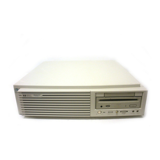
Product Information System Unit Front Panel Controls and LEDs System Unit Front Panel Controls and LEDs Before powering on your system, you should become familiar with the system unit controls. Figure 1 shows the system unit front panel controls. Removable Storage Devices Power Switch Power LED... -
Page 29: System Power Switch
Use the Power switch to power the system unit on and off. NOTICE: There is no need to manually shut down the HP- UX operating system on your workstation before powering it off. When you turn off the power switch, your workstation automatically shuts down the operating system before terminating the power. -
Page 30: Audio Controls
Product Information System Unit Front Panel Controls and LEDs Audio Controls Next to the system LEDs are the following audio con- trols: Headset Jack Accommodates mini-headphones with a 3.5-mm diameter miniature stereo plug. Volume Control Adjusts the audio output volume to the headset jack or line out. -
Page 31: Removable Storage Devices
Removable Storage Devices The Models B132L/B132L+/B160L/B180L support the following removable storage devices: • CD-ROM Disc Drive • DDS-Format Tape Drive • Floppy Diskette Drive NOTICE: Due to space limitations, a DDS-format tape drive and a CD-ROM drive cannot both be mounted in the system at the same time. -
Page 32: System Unit Rear Panel Connectors
Security Loop Monitor Pullout Card Audio Audio Line Out Line In LAN-TP HP Parallel Figure 2 System Unit Rear Panel Connectors Fast, Wide SCSI or Ultra, Wide SCSI (B132L+/B180L only) PS/2 Mouse PS/2 Keyboard Power LAN-AUI Serial 1 Serial 2... -
Page 33: Security Loop
Security Loop The security loop provides a means of locking the storage tray, with a padlock or other locking device, to prevent unauthorized removal from the system. Audio Connectors Your workstation has audio input and output capability through external input and output connectors on the rear panel and through an internal speaker. - Page 34 Product Information System Unit Rear Panel Connectors • Audio Input Line In Mono microphone (on the front panel) compati- ble with 1.5V phantom supply (bias voltage supplied by the system). CD-ROM audio (if internal CD-ROM is in- stalled) • Audio Output Line-out Headphone (on the front panel) Built-in mono speaker...
-
Page 35: Audio Electrical Specifications
Table 1 Audio Electrical Specifications Frequency Response Input Sensitivity/Impedance Line In Microphone Max Output Level/Impedance Line Out Headphone Speaker (internal) Output Impedance Line Out Headphone Signal to Noise* Line Out Headphone Speaker Line In Microphone THD (w nominal load) Line Out Headphone Speaker Line In... -
Page 36: Keyboard Connectors
HP Parallel I/O Connector The 25-pin HP Parallel I/O interface uses Centronics interface protocols to support peripheral devices such as printers and plotters. Consult the documentation that accompanies each peripheral device for specific information concerning its use. -
Page 37: Serial I/O Connectors
Serial I/O Connectors You can attach a variety of pointing devices (such as a mouse or trackball), or peripheral devices to the Serial Input/Output (SIO) ports on the B132L/B132L+/ B160L/B180L workstation. Peripheral devices include printers, plotters, modems, and scanners. Consult the documentation that accompanies each pointing or peripheral device for specific information concerning its use. -
Page 38: Scsi Connectors
Product Information System Unit Rear Panel Connectors SCSI Connectors Use the single-ended and fast, wide connectors to con- nect external SCSI devices such as DDS-format tape drives and CD-ROM drives. Consult the documenta- tion that accompanies each SCSI device for specific information concerning its use. -
Page 39: Monitors
Monitors You can use one of the following HP monitors with your workstation: • 17-inch, 1280x1024 color monitor (A4330) • 20-inch, 1280x1024 color monitor (A4331) Before using your monitor you should become famil- iar with its controls, connectors, and indicators. For this information, consult the documentation that was packaged with your monitor. -
Page 40: Operating System Overview
Your workstation uses the HP-UX operating system, version 10.20 or greater. Instant Ignition systems, (systems with preloaded software), have X-windows and either the HP VUE or the HP CDE graphical user interface installed and configured. Please refer to the “Instant Ignition System Configura- tion Information”... -
Page 41: Important Information You Need To Note
• Internet Protocol (IP) address • Subnetwork mask NOTICE: For help with these, refer to Using your HP Workstation. LANIC ID Locate the contents label that comes with the worksta- tion shipping carton. Find the LANIC ID listed there and write it down in the space provided:... -
Page 42: Ip Address And Subnetwork Mask Information
Product Information Important Information You Need to Note 2 In a terminal window, enter the following at the prompt: /usr/sbin/lanscan You will see a table similar to Table 3. Table 3 Sample LANSCAN COMMAND TABLE Hardware Station Path Address 2.0.2 0x0800091595EE The LANIC ID in this example is 0800091595EE. -
Page 43: Networking Overview
For information on set- ting up and using electronic mail on your workstation, contact your system administrator and also see the Using Your HP Workstation manual that came with your workstation. telnet The telnet application uses the TELNET protocol to communicate with another computer system on the network. -
Page 44: Rlogin
Protocol. Use ftp to copy files between your work- station and another computer system on the network. For more information, see the Using Your HP Work- station manual that came with your workstation and read the on-line man page by entering the following at... -
Page 45: Rcp
For more information, see the Using Your HP Workstation manual that came with your worksta- tion and read the on-line man page by entering the fol- lowing at a command-line prompt:... - Page 46 Product Information Networking Overview...
-
Page 47: Environmental/Installation/Pm
Environmental/Installation/... - Page 48 Environmental/Installation/PM This chapter lists the environmental specifications and regulatory requirements for the system. Installation and preventive maintenance information, if applicable, is also provided.
-
Page 49: Environmental Specifications
Environmental Specifications Table 4 lists the environmental specifications for this workstation. Table 4 Environmental Specifications Type Altitude Operating Non-operating DC magnetic field Operating Non-operating Electromagnetic Interference (EMI) Emissions Susceptibility Electrostatic Discharge Air discharge Contact discharge Humidity (Non-condensing) Operating Leakage Current Temperature Operating Non-operating... -
Page 50: Environmental Specifications
Environmental/Installation/PM Environmental Specifications Table 4 Environmental Specifications Type Operating random Swept sine survival Random survival Acoustics Specifications 0.21 G rms, 5-50 Hz 0.5 G peak, 5-500 Hz 2.09 G rms, 5-500 Hz <5 bels 5-30˚ C <6 bels 30-40˚ C... -
Page 51: Installation
Environmental/Installation/PM Installation Installation Refer to the Hardware Install Card Model B132L/B160L, (Part Number A4190-90010) for sys- tem installation information. Preventive Maintenance The system unit requires no preventive maintenance. Some removable media storage devices require opera- tor preventive maintenance. Refer to the B132L/B132L+/B160L/B180L Owner’s Guide (Part Number A4190-90023) for more information. - Page 52 Environmental/Installation/PM Preventive Maintenance...
-
Page 53: Configuration
Configuration... - Page 54 Configuration This chapter provides details about setting up and changing the system configuration.
-
Page 55: Workstation Configurations
Configuration Workstation Configurations Workstation Configurations Refer to the HP 9000 B Class Configuration Guide for a complete list of supported accessories, peripherals, and operating systems for this workstation. -
Page 56: Fru Configurations
Configuration FRU Configurations FRU Configurations This section provides information for setting up or changing the configuration of the system Field Replaceable Units (FRUs). Internal Storage Configurations Each storage device is restricted as to where in the storage tray it may be installed. Before installing a storage device, use Figure 3 and Table 5 to determine which disk tray position is correct for your device. -
Page 57: Storage Configurations
Table 5 Storage Configurations Disk Tray Supported Devices Position Floppy Drive CD-ROM DDS-Tape Single-Ended SCSI Disk Fast Wide SCSI Disk * Ultra Wide SCSI Disk** Single-Ended SCSI Disk Fast Wide SCSI Disk * Ultra Wide SCSI Disk** * Fast Wide SCSI devices are supported only with the optional Fast Wide SCSI controller. -
Page 58: Default Scsi Ids
Configuration FRU Configurations Table 6 lists the recommended SCSI IDs for internal storage devices. NOTE: There are no jumper settings to change for the floppy drive. These SCSI IDs are the default IDs for each storage device. If an existing device already uses an ID, select an alternate ID. -
Page 59: Early Model Cd-Rom Drive Scsi Address/Jumper Settings
The following figures show the CD-ROM and DDS tape drive SCSI address and jumper settings. For jumper settings for other types of drives, refer to the label on your hard drive for specific jumper informa- tion for that device. NOTE: Remove or disable the terminators on all drives (disk, CD- ROM, and DDS). -
Page 60: Later Model Cd-Rom Drive Scsi Address/Jumper Settings
Configuration FRU Configurations Figure 5 Later Model CD-ROM Drive SCSI Address/Jumper Settings... -
Page 61: Early Model Dds-Dc Tape Drive Scsi Address/Jumper Settings
SCSI ID Figure 6 Early Model DDS-DC Tape Drive SCSI Address/Jumper Settings Configuration FRU Configurations SCSI ID... -
Page 62: Later Model Dds-Dc Tape Drive Scsi Address/Jumper Settings
Configuration FRU Configurations Figure 7 Later Model DDS-DC Tape Drive SCSI Address/Jumper Settings... -
Page 63: Dds-2 Tape Drive Scsi Address/Jumper Settings
Configuration FRU Configurations Figure 8 DDS-2 Tape Drive SCSI Address/Jumper Settings... -
Page 64: Dds Drive Switch Settings For Data Compression Operation Mode
Configuration FRU Configurations Figure 9 DDS Drive Switch Settings for Data Compression Operation Mode... -
Page 65: Allowable Memory Configurations
Configuration FRU Configurations Allowable Memory Configurations This workstation has 6 memory slots, labeled 0A, 0B, 1A, 1B, and 2A, 2B. The memory configuration is 32 MB to 768 MB installed in pairs of 16 MB, 32MB, 64 MB, or 128 MB memory modules. Memory modules must be installed in pairs of equal capacity. -
Page 66: Memory Connectors
Configuration FRU Configurations Memory Module Connectors Figure 10 Memory Connectors See chapter 5 of this manual for details on installing memory modules. White Ejector Tabs... -
Page 67: Monitor-Type Selection
Monitor-Type Selection The built-in graphics in the Model B132L/B132L+/ B160L/B180L workstation supports the following two monitors: • 17-inch, 1280x1024 color monitor (A4330) • 20-inch, 1280x1024 color monitor (A4331) The monitor type does not have to be changed on this workstation since the workstation is set up to support these monitors. -
Page 68: Graphics Configuration Consideration
Configuration Graphics Configuration Consideration Graphics Configuration Consideration If you are installing a graphics option, read the infor- mation in this section first. Special Video Configuration Statements The following statements apply only to those applica- tions which include a cable connected to the S-Video connector on the A4248A card. -
Page 69: Graphics Paths
Configuration Graphics Configuration Consideration Graphics Paths graphics(0) is the built-in 8-plane graphics adapter. graphics(1) and graphics(2) are graphics adapters installed in option slots 1 and 2. When a dual display graphics adapter (an adapter which has two video output connectors) is installed, the video connector on the left (when looking at the system from the rear) is graphics(NA) and the video connector on the right is graphics(NB). -
Page 70: Graphics Configuration Restrictions
Configuration Graphics Configuration Consideration Graphics Configuration Restrictions The system supports only four graphics displays at a time. A “display” is a video output port or connector. For example, the Dual Visualize Enhanced Graphics Card (A4451A) is a dual display card. It has two exter- nal video connectors so it accounts for two of the max- imum of four displays. -
Page 71: Troubleshooting
Troubleshooting... - Page 72 Troubleshooting This chapter provides information about isolating a failing component, known as a Field Replaceable Unit (FRU), in a Model B132L/B132L+/B160L/B180L workstation.
-
Page 73: Getting Ready To Troubleshoot
Getting Ready to Troubleshoot Getting Ready to Troubleshoot To troubleshoot a B132L/B132L+/B160L/B180L workstation, you must be familiar with the HP-UX operating system and be able to start and stop pro- cesses. You should also be familiar with the boot ROM diagnostics, ISL diagnostics, and the Support Tools Manager online tests, which we describe in this chapter. -
Page 74: Power On Troubleshooting
Troubleshooting Getting Ready to Troubleshoot Start Turn on system Power LED Lights? Fans on? Power LED Lights? Replace power supply Power LED Lights? Figure 11 Power On Troubleshooting Flowchart 1 Next Chart Replace CPU board Replace the following FRUs one at a time until LED lights: 1. -
Page 75: Selftests Troubleshooting
Flowchart 2 Start Power LED Lights? Replace CPU board or backplane Powerup display appears normal? error messages displayed? Go to HP-UX flowchart Figure 12 Selftests Troubleshooting Troubleshooting Getting Ready to Troubleshoot Selftests pass? Replace indicated Check monitor Configuration Troubleshoot the... -
Page 76: Hp-Ux Compatible Mode Troubleshooting
Check the following: 1. Interface cables 2. Mass storage devices and their files 3. System unit interfaces Figure 13 HP-UX Compatible Mode Troubleshooting Flowchart 3 Does Boot List Select OS to boot appear? System Do other with LAN system units cable &... - Page 77 Can you log in? all peripherals work? programs load and run? Figure 14 HP-UX Compatible Mode Troubleshooting (Continued) Troubleshooting Getting Ready to Troubleshoot Flowchart 4 Run offline ISL Diagnostics Refer to Chapter 5 of System Administrator’s Tasks Run offline and online diagnostics...
-
Page 78: Dealing With A Boot Failure
Troubleshooting Dealing with a Boot Failure Dealing with a Boot Failure To start this workstation from an operating system stored on a device different from the usual boot device, to boot from a different disk, or to boot from another type of device (such as a DDS tape drive), see the following situations and examples that use the Boot Console Interface. - Page 79 ISL is the program that actually controls the loading of the operating system. By interacting with ISL, you can choose to load an alternate version of the HP-UX oper- ating system. For example, if the usual kernel (/stand/vmunix) on the root disk (fwscsi.6.0) has become corrupted, boot the...
-
Page 80: Searching For Bootable Media
Troubleshooting Dealing with a Boot Failure Searching for Bootable Media To list all devices that may contain bootable media, go to the Main Menu of the Boot Console Interface and then type the following at the prompt: search ipl The search may turn up more devices than there are lines on the display. -
Page 81: Stable Storage
Dealing with a Boot Failure Stable Storage Stable Storage is non-volatile memory associated with each PA-RISC processor module. Stable storage is used by the processor (CPU) to store device path information, the state of the boot flags, HPMC error information, and operating system initialization data. Boot Command Notations The boot command supports the following two notations: •... -
Page 82: Isl Environment
• Run offline diagnostic programs (TDIAG, IOMAP). • Provide automatic booting of the HP-UX O/S after power-on or reset. The ISL program provides a standalone environment for loading offline diagnostic and utility programs from the LIF directory. -
Page 83: Selftest Failures
Selftest Failures Chassis codes are the key to debugging selftest errors. If a failure is found during selftest, chassis codes are displayed in the diagnostic LEDs. the LED error code To get additional information about failures from the boot console interface, use the Service menu pim, pdt, and Chassis Code commands. -
Page 84: Led Error Codes
Troubleshooting Selftest Failures Table 7 LED Error Codes RS-232 LED Value Chassis Code Range 5000 - 500F 8000 - 8FFF CD00 - CDff* 8500, 8501 8C00-8CFF INIT/TEST code Any fault not in this table including 1000-101C CBF0 - CBFF 1001 A088 - A0FF Description I/O System FAULT... -
Page 85: Chassis Codes
Table 7 LED Error Codes RS-232 LED Value Chassis Code Range Chassis Codes Below are definitions for all L2 chassis display codes. The codes are organized in approximate numerical order for ease of reference. The ‘ostat’ or operating state of the machine have been omitted. - Page 86 Troubleshooting Selftest Failures 0015 DINO_BRDG_FEAT_INIT ister 0016 DINO_PCIROR_INIT 0017 DINO_PCIWOR_INIT 0018 DINO_TLTIM_INIT * = Unexpected interrupts that should never occur in PDC code. Code Name 1x01 UNEXPECTED_INTERRUPT 1x02 UNEXPECTED_INTERRUPT (unused)* 1x03 UNEXPECTED_INTERRUPT 1x04 UNEXPECTED_INTERRUPT 1x05 UNEXPECTED_INTERRUPT 1x06 UNEXPECTED_INTERRUPT 1x07 UNEXPECTED_INTERRUPT tion trap* 1x08 UNEXPECTED_INTERRUPT...
- Page 87 1078-1079 CPU_SAR 107A-1080 CPU_EX_DEP 1081-1083 CPU_BB 1084-1089 CPU_CR 108B-108D CPU_EXT_INT selftest 108E-1093 CPU_ITIME 1094-1097 CPU_SHADOW selftest 1098-1099 CPU_DIAGS selftest 10A0 COPROC selftest 10A1 COPROC_REG 10A2 COPROC_INSTR selftest 10A3 COPROC_TRAPS 10A4 10AF FPU_S_DISABLED 10B0 TLB_INIT 10B3-10B4 TLB_ADDR 10B6-10B7 TLB_PROT 10C0 BAD_PDH_SPEED 10CE CPU_EXTINGUISH via PDC_PROC call...
- Page 88 Troubleshooting Selftest Failures 2070 DCACHE_RAM 2071 DCACHE_RAM_DATA_ERR 2072 DCACHE_RAM_TAG_ERR 2073 DCACHE_RAM_LOAD_ERR 2080-2x84 DTAG 2090-2x95 CACHE_DERR 20A0-2xA8 CACHE_BIST 20B0 DCACHE_PARITY 20B1 DCACHE_TAG_PARITY the tag 20B2 DCACHE_WORD0_PARITY word 0 20B3 DCACHE_WORD1_PARITY word 1 20C0 ICACHE_PARITY 20C1 ICACHE_TAG_PARITY 20C2 ICACHE_WORD0_PARITY 20C3 ICACHE_WORD1_PARITY 21.. second level cache Code Name Meaning...
- Page 89 FLT extended info same as 2131 2137 SLC_TAG_PATT_ADDR_ERR FLT extended info same as 2131 2138 SLC_TAG_PATT_TAG_ERR FLT extended info same as 2131 2140 SLC_MISS 2141 SLC_TAG_MISS_DATA_ERR FLT extended info same as 2131 2142 SLC_TAG_MISS_NO_MISS FLT extended info same as 2131 2143 SLC_TAG_MISS_ADDR_ERR FLT extended info same as 2131...
- Page 90 Troubleshooting Selftest Failures Actual M_RD_CHK[0:15] Actual M_RD_CHK[16:31] Expected M_RD_CHK[0:15] Expected M_RD_CHK[16:31] 2168 SLC_ERR_NML_DATA_ERR FLT extended info same as 2167 2169 SLC_ERR_MEM_RD_CHK_ERR FLT extended info same as 2167 216A SLC_ERR_SLC_RD_CHK_ERR FLT extended info same as 2167 216B SLC_ERR_NML_SLCSTAT_ERR FLT extended info same as 2152 216C SLC_ERR_MEM_SLCSTAT_ERR FLT extended info same as 2152...
- Page 91 FLT extended info same as 2152 2193 SLC_DMA_TEST_SLCSTAT_ERR FLT extended info same as 2152 2194 SLC_DMA_UNEXP_SLC_SIZE 2195 SLC_DMA_SETUP_DATA_ERR FLT extended info same as 2157 2196 SLC_DMA_TEST_DATA_ERR FLT extended info same as 2157 21F0 SLC_INIT Code Name 3000 ROM_XSUM 3001 PDH_CNTRL 3002 SCR_SELFTEST 3003...
- Page 92 Troubleshooting Selftest Failures 5xy3 MODE _PHASE_ERROR 5xy4 PARITY_ERROR 5xy5 PROTOCOL_ERROR 5xy7 DIR_ERROR 5xy8 BROAD_ERROR 5xy9 IMPROPER_ACCESS_ERROR 5xyA ILLEGAL_RESPONSE 5xyB BUS_TIMEOUT 5xyD WATCHDOG_TIMEOUT 5xyE GBOA_TOC 504F BUS_PMAE_HPMC (unconfigured mem space) 505F US_PIOAE_HPMC timed out 506F BUS_DMDP_HPMC on GSC from L2 slave 507F BUS_PMDP on GSC from L2 master...
- Page 93 7406 HPMC_SLC_ACCESS_ERR 7407 HPMC_SLC_TAG_ERR 7500 7501 GOOD_MEM_FAILED to run OS 7502 BCH_MEM_FAILED to run BCH 7604 BAD_MCT_MEM_TEST_STATUS No bits set in Test Status 7701 USING_ALT_CONFIG config 7702 MEMORY_INIT_ONLY tialized only 7703 SIM_LOADING_WARNING 7704 RAM_BUS_WARNING 7705 GOOD_MEM_GOOFY 770F SMC_REV_1_WARNING tine being used 7800 PDT_DISABLED_WARNING 7800...
- Page 94 Troubleshooting Selftest Failures 7FFF CATASTROPHIC_MEM_ERR Code Name 8000-8004 GECKOBOA_REG 802B IO_BUS_OVERLAP on core and carrier 803D TOO_MANY_GRAPHICS overlap 80F3 ERR_READING_IODC_BYTES trieve header info 80F4 ERR_READING_EINIT turn entry_init 80F5 ERR_EXEC_EINIT entry_init 80F6 ERR_READING_EIO turn entry_io 80F7 ERR_ENTRY_IO_ERR ENTRY_IO 80F8 INVALID_DEVICE_CLASS random or tftp 80F9 ERR_READIN_ETEST turn entry_test...
- Page 95 placed by the FRU slot number where appropriate. Code Name 8C05 PCI_PATH_ERR 8C06 PCI_BIST_TEST test 8C07 PCI_BIST_ERR 8C08 PCI_ALLOC_ERR 8C09 PCI_MEM_MANAGER_ERR 8C0A PCI_MEM_TYPE_ERR 8C0B PCI_MAX_BUS_EXCEEDED 8C0C PCI_DEV_NOT_CONFIGURED 8C0D PDC_SYS_MAP_OVERFLOW (during PCI bus walk) 8C0E SYS_PCI_MAP_OVERFLOW 8C0F PCI_INT_KLUDGE_WARN for flawed labproto BP For the following section of PCI-related chassis codes: The “1”...
- Page 96 Troubleshooting Selftest Failures C252 TEST_DUAL_ISSUE C260 INTRLV_RAM_TEST C261 TEST_1ST_PAGES C263 TEST_WRITE C264 TEST_READ_WRITE C265 TEST_READ C270 UPDATING_CONFIG C280 CONFIG_TO_EEPROM C2A0 FLAT_CONFIG C2B0 FLAT_RAM_TEST C2C1 MEM_RESET_SOFT C2C2 NON_DEST_RAM_TEST C2C3 MIOC_ERR test C2E0 MEM_STUFF_DONE C300 MONARCH_TEST extended s C3FF LATE_MONARCH_TEST extended selftests C400 GET_SS_CONS sole path...
- Page 97 graphics at HPA F6 C654 INIT_MONITOR_F4 graphics at HPA F4 C700 GET_MFG_DFLTS C740 INIT_OTHR_PATH boot path C750 TEST_OTHR_PATH other boot path C780 LOAD_IPL_OTHR_PATH primary boot path C7F0 OTHR_IPL_FAULT_ ing IPL C7F1 BAD_IPL_ADDR_OTHR not 2K byte aligned C7F2 BAD_LIF_MAGIC_OTHR on media C7F3 BAD_IPL_SIZE_OTHR n*2K bytes, or >...
- Page 98 Troubleshooting Selftest Failures CBFE HPMC_DURING_TOC CBFF MULTIPLE_HPMCS CC0x OS_RENDEZVOUS CC1x CC2x CPU_RENDEZVOUS CC3x CC4x MEM_CPU_RENDEZVOUS Code Name CD00 INITIALIZE_IO CD08 IOA0_INIT For the following section of chassis codes: The “1” (in codes of the form CD1x) refers to the (sole) GSC bus, #1 TEST: Looking for hardware on GSC bus INIT: Found the hardware being looked for WARN: Not able to use the hardware even...
-
Page 99: Running System Verification Tests
Running System Verification Tests Running System Verification Tests HP-UX uses an online diagnostics product called the Support Tools Manager that allows system operation verification. Three interfaces are available with the Support Tools Manager: a command line interface (accessed through the cstm command), a menu-driven interface... - Page 100 Troubleshooting Running System Verification Tests To access the Support Tools Manager, perform the fol- lowing steps: 1 In a terminal window, type the following at the # prompt to invoke the command line interface: # cstm 2 The following message appears: Support Tool Manager Version A.01.00 Type ‘help’...
-
Page 101: Running Ode-Based Diagnostics
Running ODE-Based Diagnostics Running ODE-Based Diagnostics The Offline Diagnostic Environment (ODE) consists of diagnostic modules for testing and verifying system operation. ODE provides all the necessary functions for the user to load specified tests and interact with those tests. ODE is an ISL utility. To boot ODE: 1 Invoke the ISL environment from the system disk. - Page 102 Troubleshooting Running ODE-Based Diagnostics • mapper - identifies the configuration of HPPA systems. It displays path, identification, and revision information of I/O components, configuration of memory controllers, processors, co-processors, cache, and TLB, as well as processor board component revisions and values of vari- ous HPPA system identifiers, revisions, and capabilities.
-
Page 103: Dealing With Hpmc (Uncorrectable Error)
The power-on sequence follows this path: Power-on -> Selftest -> Console Path -> Boot Admin Mode -> Boot Path -> ISL Mode -> HP-UX Mode When the hardware detects an unrecoverable (HPMC) error in the HP-UX environment, an error message, referred to as an HP-UX Kernal Tombstone is dis- played on the monitor. -
Page 104: Pim_Info Action Table
Troubleshooting Dealing with HPMC (Uncorrectable Error) Table 8 PIM_INFO Action Table Cache Check Check Check Type Word Word Word 0x80000000 0x40000000 0x20000000 0x00210003 0x20000000 0x00310007 0x20000000 0x00310007 0x20000000 0x00310007 0x20000000 0x00310007 0x20000000 0x00310007 Note 1 When more than one failed FRU is identified, run the appropriate diagnostics to isolate the failed FRU. -
Page 105: Hpmc Caused By A Multi-Bit Memory Parity Error
HPMC Caused by a Multi-Bit Memory Parity Error An HPMC interruption is forced when a multi-bit memory parity error is detected during a “DMA read” operation of fetching an I/D cache line (32 bytes). Table 9 shows an example of the HPMC error infor- mation retrieved from Stable Storage by the PIM_INFO command during the Boot Administration environment. -
Page 106: Interpreting The Table
Troubleshooting Dealing with HPMC (Uncorrectable Error) Interpreting the Table The values in the Bus Check and System Responder Address words indicate that a multi-bit memory parity error was detected by logic in the memory module. Ignore the value in the System Controller Status word. The System Responder contains the SPA of the faulty SIMM pair. -
Page 107: Determining The Faulty Simm Pair
Determining the Faulty SIMM Pair The address given by the System Responder Address is contiguous, even though empty slots are permitted. Memory boards are installed in pairs of the same memory capacity. The operating system starts map- ping memory at Pair 3, if it exists. In other words, it maps starting with the highest numbered pair through to the Pair 0. - Page 108 Troubleshooting Dealing with HPMC (Uncorrectable Error) Table 10 Memory Address Ranges Pair (3 thru 0) _________ _________ _________ _________ _________ _________ _________ _________ _________ _________ _________ _________ _________ _________ _________ For example, if the system configuration is: Pair 3: 32 MB SIMMs = 64 MB total for pair Pair 2: 16 MB SIMMs = 32 MB total for pair Pair 1:...
-
Page 109: Example Table
The SIMM address ranges are: Pair 3: Addresses 0x00000000 - 0x03FFFFFF Pair 2: Addresses 0x04000000 - 0x05FFFFFF Pair 1: Addresses 0x06000000 - 0x09FFFFFF Pair 0: Addresses 0x0A000000 - 0x0AFFFFFF Table 11 Example Table Pair (3 thru 0) ____3____ ____3____ ____3____ Pair 3 ____3____ (32 MB... - Page 110 Troubleshooting Dealing with HPMC (Uncorrectable Error) Table 11 Example Table Pair (3 thru 0) ____1____ ____1____ ____1____ Pair 1 ____1____ (32 MB ____1____ SIMMs) ____1____ ____1____ ____1____ Pair 0 ____0____ (8 MB ____0____ SIMMs) _________ _________ _________ _________ _________ _________ 2 Determine the SIMM pair that contains the System Re- sponder Address (as shown using the PIM_INFO com- mand) within its range.
- Page 111 NOTICE: Addressing starts at Pair 3, not Pair 0. A If the System Responder Address (as shown using the PIM_INFO command) is between 0x000000 and 0x03FFFFFF: Error in Pair 3 B If the System Responder Address (as shown using the PIM_INFO command) is between 0x04000000 and 0x05FFFFFF: Error in Pair 2 C If the System Responder Address is between...
-
Page 112: Hpmc Caused By A Data Cache Parity Error
Troubleshooting Dealing with HPMC (Uncorrectable Error) SIMM pair identified in this procedure. Return the sys- tem state (for example, FASTBOOT) to the original condition. HPMC Caused by a Data Cache Parity Error An HPMC interruption is forced when a data parity error is detected during a Load instruction to the mem- ory address space or during a data cache flush opera- tion. -
Page 113: Changing The Console To External Terminal
Dealing with HPMC (Uncorrectable Error) The value in the CPU State word indicates that register values and addresses stored in Stable Storage at the time of the HPMC were saved. The value on the Cache Check word identifies that logic in the processor module detected a (data) cache parity error. - Page 114 Troubleshooting Dealing with HPMC (Uncorrectable Error)
-
Page 115: Field Replaceable Units
Field Replaceable Units... - Page 116 NOTICES: There is no need to manually shutdown the HP-UX operating system on the workstation before switching it off. When the power switch is turned off, the workstation automatically shuts down the operating system before terminating the power.
-
Page 117: Exchange And Nonexchange Part Numbers
Exchange and Nonexchange Part Numbers In this chapter we refer to exchange and nonexchange part numbers. You must return FRUs with exchange part numbers in exchange for a replacement FRU. Do not return FRUs with nonexchange part numbers. You may discard them. -
Page 118: Main Tray Frus
Field Replaceable Units Exchange and Nonexchange Part Numbers Figure 16 shows the Main Tray FRUs for the B132L/ B132L+/B160L/B180L workstation. The numbers correspond to item numbers in Table 13 and Table 14. Figure 16 Main Tray FRUs... -
Page 119: Storage Tray Frus
Field Replaceable Units Exchange and Nonexchange Part Numbers Figure 17 shows the Storage Tray FRUs for the B132L/B132L+/B160L/B180L workstation. The numbers correspond to item numbers in Table 13 and Table 14. Figure 17 Storage Tray FRUs Table 13 lists the exchange parts, and Table 14 lists the nonexchange parts in the B132L/B132L+/B160L/ B180L workstation. -
Page 120: Exchange Parts Fru List
Field Replaceable Units Exchange and Nonexchange Part Numbers Table 13 Exchange Parts FRU List Figure Part Number Number A4190-69028 A4190-69013 A4190-69016 A4190-69032 A1658-69009 A2084-69016 A1658-69010 A1658-69020 A4081-69003 A1658-69021 A4218-69016 A1658-69022 C1536-69201 C1539-69201 C1537-69201 A1648-60015 A1658-60019 A4200-69040 A4200-69045 A2579-69001 A2580-69001 A1236-69001 A3828-69001 A3829-69001 A3830-69001... - Page 121 Field Replaceable Units Exchange and Nonexchange Part Numbers...
-
Page 122: Nonexchange Parts Fru List
Field Replaceable Units Exchange and Nonexchange Part Numbers Table 14 Nonexchange Parts FRU List Figure Part Number Number A4190-66500 A4190-66523 0950-3021 Not Shown A4190-66501 Not Shown A4190-61601 Not Shown A4190-61602 Not Shown A4323-63001 A4190-62020 A4190-62030 Not Shown A4190-62022 A4190-62025 A4190-62043 A4190-62048 A4190-62051 Not Shown... - Page 123 Table 14 Nonexchange Parts FRU List Figure Part Number Number Not Shown A2263-40042 Not Shown A4190-00049 A4190-84009 A4578-84001 A4190-84010 A4190-84012 Not Shown A4190-61603 A4081-62021 A4190-60010 A4190-62024 Not Shown 8120-6861 Not Shown A4452-66501 A4190-40016 Not Shown 0624-0727 Not Shown 5180-1344 Not Shown A1658-62016 Not Shown 1252-4367...
-
Page 124: Fru Removal And Replacement
1 Power off the system, the monitor, and any peripheral devices. NOTICE: There is no need to manually shut down the HP- UX operating system on the workstation before powering it off with the power switch. When the power switch is turned off, the workstation automatically shuts down the operating system before terminating the power. -
Page 125: Removing The Floor Stand
Figure 18 Removing the Floor Stand CAUTION: Follow normal ESD, anti-static precautions when handling the workstation or any of its components. Failure to do so can cause component degradation or failure. Field Replaceable Units FRU Removal and Replacement... - Page 126 Field Replaceable Units FRU Removal and Replacement 7 Lay the workstation on a flat stable surface, such as a table top or floor. 8 If installed, remove any locking device from the storage tray security tab on the rear of the system unit.
-
Page 127: Main Tray Assembly
Main Tray Assembly Perform the following steps to remove the main tray assembly from the system unit: 1 Completely loosen the four thumb screws on the rear of the system unit, as shown in Figure 19. Figure 19 Removing the Main Tray Assembly 2 Place one hand on the top of the system unit and push, while using your other hand to pull on the handle on the rear panel. -
Page 128: Removing Memory Modules
Field Replaceable Units FRU Removal and Replacement Removing Memory Modules Before removing memory modules, remove the Main Tray Assembly from the system unit. Refer to Chapter 3 for information about memory con- figurations. Perform the following steps to remove memory mod- ules: 1 Locate the memory modules on the CPU board, as shown in Figure 20. -
Page 129: Removing The Memory Retainer
Field Replaceable Units FRU Removal and Replacement 2 Pull the tab on the memory retainer and slide it toward the front of the main tray to remove it, as shown in Figure 21 Figure 21 Removing the Memory Retainer... -
Page 130: Removing A Memory Module
Field Replaceable Units FRU Removal and Replacement 3 To remove a memory module, push the ejector tabs on each side of the module. Lift the memory module up and out of the connector and place it on a static-free surface. Figure 22 shows how to remove a memory module. -
Page 131: Installing Memory Modules
Installing Memory Modules Before installing memory modules, remove the Main Tray Assembly from the system unit. Refer to Chapter 3 for information about memory configurations. Perform the following steps to install memory modules: 1 Locate the memory connectors on the CPU board, as shown in Figure 23. -
Page 132: Removing The Memory Retainer
Field Replaceable Units FRU Removal and Replacement 2 Pull the tab on the memory retainer and slide it toward the front of the main tray to remove it, as shown in Figure 21 Figure 24 Removing the Memory Retainer 3 Close the ejector tabs on each side of the memory con- nector to lessen the force required to seat the memory module. -
Page 133: Installing Memory Modules
4 Line up the memory module with the guides making sure that the notched end of the memory module is toward the white ejector tabs (front of the main tray), as shown in Figure 25. White Ejector Tab Figure 25 Installing Memory Modules 5 Press firmly and evenly on the memory module to ensure that it is fully seated. -
Page 134: Second Level Cache Boards
Field Replaceable Units FRU Removal and Replacement Second Level Cache Boards Before removing second level cache boards, remove the main tray assembly. 1 Locate the cache board connectors on the CPU board, as shown in Figure 26. Cache Board Connectors Figure 26 Cache Boards Location... -
Page 135: Removing Second Level Cache Boards
2 To remove a second level cache board, swing the ejector tabs on each side of the board out and away from the board, as shown in Figure 27. Lift the board up and out of the connector and place it on a static-free surface. Figure 27 Removing Second Level Cache Boards NOTICE:... -
Page 136: Storage Tray Assembly
Field Replaceable Units FRU Removal and Replacement Storage Tray Assembly Before removing the Storage Tray Assembly, remove the Main Tray Assembly from the system unit. The Storage Tray Assembly does not have to NOTICE: be removed from the system unit to access a hard disk drive or the 3.5-inch floppy drive. -
Page 137: Disconnecting The Storage Tray Assembly
2 Remove the storage tray retaining screw, as shown in Figure 29. 3 Disconnect the cables from the system board and the backplane, as shown in Figure 29. FWSCSI Storage Tray Power SESCSI CD Audio Floppy Connector Figure 29 Disconnecting the Storage Tray Assembly Field Replaceable Units FRU Removal and Replacement Retaining Screw... -
Page 138: Removing The Storage Tray Assembly
Field Replaceable Units FRU Removal and Replacement 4 Hold the storage tray with both hands and slide it toward the front of the main tray approximately an inch, then lift it straight up to remove it. Figure 30 Removing the Storage Tray Assembly NOTICE: When replacing the storage tray, use the following procedure:... -
Page 139: Storage Tray Cover
Field Replaceable Units FRU Removal and Replacement Storage Tray Cover To remove the storage tray cover press in the two cover locking tabs then lift the front end of the cover and slide it forward off of the pins in the rear, as shown in Figure 31. -
Page 140: Disk Filler Panel
Field Replaceable Units FRU Removal and Replacement Disk Filler Panel NOTICE: If you remove a disk filler panel, you must replace it or install a removable media storage device in its place. Before removing a disk filler panel, remove the Stor- age Tray Assembly. -
Page 141: Cd-Rom Drive Or Dds Tape Drive
CD-ROM Drive or DDS Tape Drive Before removing the CD-ROM drive or DDS Tape drive, perform the following procedures: Remove the Main Tray Assembly. • Remove the Storage Tray Assembly. • Remove the Storage Tray Cover. • NOTICE: Refer to Chapter 3 for supported storage tray configurations. - Page 142 Field Replaceable Units FRU Removal and Replacement 2 Disconnect the power and data cables from the device. 3 Slide the device completely out of the storage tray and place it on a static-free surface.
-
Page 143: 3.5-Inch Floppy Disk Drive
3.5-Inch Floppy Disk Drive Perform the following procedures before removing a floppy disk drive: Remove the Main Tray Assembly from the system • unit. Remove the Storage Tray Cover. • The Storage Tray Assembly does not have to NOTICE: be removed from the Main Tray to access a hard disk drive or the 3.5-inch floppy drive. -
Page 144: Removing The Floppy Disk Carrier
Field Replaceable Units FRU Removal and Replacement 2 Lift the rear of the floppy disk carrier, push the carrier to- ward the rear of the disk tray, then lift the front of the floppy disk carrier from the Storage Tray, as shown in Figure 35. -
Page 145: Removing The Floppy Disk Drive
3 Lift the floppy drive straight up to remove it from the floppy carrier, as shown in Figure 36. Figure 36 Removing the Floppy Disk Drive NOTICE: When replacing the floppy drive in the carrier, make sure to align the pin in the carrier with the hole in the floppy drive. -
Page 146: Hard Disk Drive
Field Replaceable Units FRU Removal and Replacement Hard Disk Drive Perform the following procedures before removing a hard disk drive. Remove the Main Tray Assembly from the system • unit. Remove the Storage Tray Cover. • Remove the floppy disk drive if you are removing a •... -
Page 147: Removing A Hard Disk Drive
2 Push the locking tab toward the drive and hold it there while simultaneously sliding the drive toward the front of the storage tray, as shown in Figure 37. Figure 37 Removing a Hard Disk Drive 3 Lift the drive straight up to remove it from the Storage Tray. -
Page 148: Removing Eisa, Gsc, And Pci Option Boards
Field Replaceable Units FRU Removal and Replacement Removing EISA, GSC, and PCI Option Boards Before removing EISA, GSC, or PCI option boards from the system unit, remove the Main Tray Assembly from the system unit. NOTE: Slot 1 supports GSC or PCI option boards; slot 2 supports EISA, GSC, or PCI option boards. -
Page 149: Installing An Option Slot Blank Plate
NOTICE: If you are not replacing the board, perform the following procedure: a Install a blank plate in the rear panel, as shown in Figure 39 b Perform Steps 2 through 1 in reverse order. Figure 39 Installing an Option Slot Blank Plate Field Replaceable Units FRU Removal and Replacement... -
Page 150: Cpu Board Assembly
Field Replaceable Units FRU Removal and Replacement CPU Board Assembly Before removing the CPU board assembly perform the following procedures: Remove the Main Tray Assembly from the system • unit. • Remove the Storage Tray Assembly from the Main Tray Assembly. -
Page 151: Determining Lan Id
FRU Removal and Replacement Determining LAN ID Enter the following at the prompt: /usr/sbin/lanscan The output is similar to the following: Hardware Station Dev Hardware Net-Interface NM Encapsulation Mjr Path Address State NameUnit State ID 2.0.2 0x08000970ECC0 0 lan0 An alternative way to find the system’s LAN ID is to use the following command at the information menu of the Boot Console Handler: lanaddress... -
Page 152: Removing The Cpu Board
Field Replaceable Units FRU Removal and Replacement Removing the CPU Board Perform the following steps to remove the CPU board from the main tray: 1 Pull the two ejector handles at the same time, as shown in Figure 40. Figure 40 Removing the CPU Board 2 Slide the CPU board out of the main tray. -
Page 153: Optional Egram Module
Optional EGRAM Module Before removing the optional EGRAM (System Graphics RAM) module, perform the following proce- dures: Remove the Main Tray Assembly from the system • unit. • Remove the Storage Tray Assembly from the Main Tray Assembly. • Remove the CPU board assembly from the Main Tray. Perform the following procedure to remove the EGRAM module: 1 To release the EGRAM module from the standoffs, use a... - Page 154 Field Replaceable Units FRU Removal and Replacement Grasp the EGRAM module from the sides and pull it straight up to disconnect it from the CPU board connector NOTICE: When replacing the EGRAM module make sure that its connector is correctly aligned with the connector on the CPU board and press down firmly to make sure that it is fully connected.
-
Page 155: System Fans And Speaker
System Fans and Speaker Before removing the fans, remove the Main Tray Assembly from the system unit. Perform the following steps to remove the system fans: 1 Locate the desired fan or speaker connector on the back- plane, push in the tab on the connector and disconnect it from the backplane, as shown in Figure 42. -
Page 156: Removing The System Fans And Speaker
Field Replaceable Units FRU Removal and Replacement 3 Lift the fan out of the top of the fan shroud, or pull the speaker out of the front of the fan shroud, as shown in Figure 43. Figure 43 Removing the System Fans and Speaker... -
Page 157: Battery
Battery Before removing the battery, perform the following procedures: • Remove the Main Tray • Remove the Storage Tray Lift the clip and slip the battery out of its holder, as shown in Figure 44. Figure 44 Removing the Battery CAUTION: Danger of explosion if battery is incorrectly replaced. -
Page 158: Power Supply
Field Replaceable Units FRU Removal and Replacement Power Supply Before removing the power supply, remove the Main Tray Assembly. 1 Remove the option board support bracket by pushing in on the locking tab and sliding it toward the rear of the main tray, as shown in Figure 45. -
Page 159: Removing The Power Supply
2 Remove the two power supply retaining screws, as shown in Figure 46. Power Supply Retaining Screws Figure 46 Removing the Power Supply 3 Pull the power supply out of the side of the main tray, as shown in Figure 46. CAUTION: To avoid damage, be sure to use two hands to remove the power supply and pull it straight out. -
Page 160: Fast Wide Scsi Controller
Field Replaceable Units FRU Removal and Replacement Fast Wide SCSI Controller Before removing the FW SCSI controller, remove the main tray assembly. To remove the FW SCSI controller, use a pair of nee- dle-nose pliers to squeeze the tabs on the standoffs so that they will pass through the board and pull the board straight out from the backplane to disconnect it. -
Page 161: Backplane
FRU Removal and Replacement Backplane Before removing the backplane, perform the following procedures: • Remove the Main Tray Assembly • Remove the Mass Storage Tray • Remove the CPU Board • Remove any EISA, GSC, or PCI option boards • Remove (optional) Fast Wide SCSCI board. -
Page 162: Disconnecting The Speaker And Fan Connectors
Field Replaceable Units FRU Removal and Replacement Perform the following steps to remove the backplane: 1 Disconnect the two fan connectors and the speaker con- nector by pushing in on the connectors locking tab and pulling the connector, as shown in Figure 48. Figure 48 Disconnecting the Speaker and Fan Connectors 2 Pull the fan and speaker cables out of the slots in the... -
Page 163: Removing The Backplane
Field Replaceable Units FRU Removal and Replacement 3 Lift the backplane on its standoffs and swing the right end out away from the backplane support, as shown in Figure 49. Figure 49 Removing the Backplane... - Page 164 Field Replaceable Units FRU Removal and Replacement...
-
Page 165: Diagrams And Pinouts
Diagrams and Pinouts... -
Page 166: Fwscsi Board Backplane Connector
Diagrams and Pinouts This chapter provides functional information about the system including tables which list pinouts for the fol- lowing connectors: • Backplane to System Board connector • Backplane PCI connector • FWSCSI board backplane connector • Backplane EISA slot connector •... -
Page 167: System Power
System Power This section provides information on the connectors and pinouts in the B132L/B132L+/B160L/B180L workstation. Table 15 lists the pinouts for the Backplane to System Board primary connector. Table 15 Backplane to System Board Connector Row A Row B Number P12v_aud spare(0) N12v_aud... -
Page 168: Backplane To System Board Connector
Diagrams and Pinouts System Power Table 15 Backplane to System Board Connector Row A Row B Number gsc_resetL_fwscsi gsc_ad(30) gsc_resetL_wax gsc_resetL_dino gsc_ad(28) gsc_ad(26) gsc_ad(25) gsc_ad(23) gsc_ad(21) gsc_ad(20) gsc_ad(19) gsc_ad(17) gsc_ad(15) gsc_ad(13) gsc_ad(12) gsc_ad(11) gsc_ad(9) gsc_ad(7) gsc_ad(5) gsc_ad(4) gsc_ad(3) gsc_ad(1) gsc_retryL gsc_gscL gsc_drrL clk_40Mhz... -
Page 169: Backplane Pci Connector
Table 16 lists the pinouts for the Backplane PCI con- nector. Table 16 Backplane PCI Connector Row A Row B Number pci_par pci_serrL pci_ad(0) pci_ad(2) pci_sboL pci_sdone pci_ad(5) pci_ad(7) pci_perrL pci_lockL pci_ad(9) pci_stopL pci_ad(12) pci_clk(3) pci_ad(14) pci_clk(4) pci_clk(5) pci_ad(16) pci_ad(18) pci_devselL pci_trdyL pci_ad(21) - Page 170 Diagrams and Pinouts System Power Table 17 lists the pinouts for the Backplane Optional Fast-Wide SCSI board connector. Table 17 FWSCSI Board Backplane Connector Row A Row B Number gsc_resetL init_addr(1) gsc_brL gsc_addvL gsc_errorL gsc_parity gsc_type(2) gsc_ad(31) gsc_ad(30) gsc_ad(28) gsc_ad(25) gsc_ad(23) gsc_ad(22) gsc_ad(20)
-
Page 171: Backplane Eisa Slot Connector (Rows F, B, E, And A)
Table 18 lists the pinouts for the Backplane to EISA Slot connector for rows F, B, E, and A. Table 18 lists the pinouts for rows H, D, G, and C. NOTE: Rows A, C, F, and H are Upper (ISA) contacts. Rows B, D, E, and G are Lower (EISA) contacts. - Page 172 Diagrams and Pinouts System Power Table 18 Backplane EISA Slot Connector (Rows F, B, E, and A) Row F Row B IRQ<6> LA<26> IRQ<5> LA<24> IRQ<4> ACCESS KEY IRQ<3> LA<16> DAK<2> LA<14> BALE LA<10> Table 19 Backplane EISA Slot Connector (Rows H, D, G, and C) Row H Row D LA<8>...
-
Page 173: Backplane Eisa Slot Connector (Rows H, D, G, And C)
Table 19 Backplane EISA Slot Connector (Rows H, D, G, and C) Row H Row D DAK<6> D<27> DAK<7> ACCESS KEY DRQ<7> D<29> MASTER16 MAKx Diagrams and Pinouts System Power Row G Row C D<26> D<28> ACCESS KEY D<30> D<31> MREQx D<10>... - Page 174 Diagrams and Pinouts System Power Table 20 lists the pinouts for the Backplane PCI slot connector in a 5.0V environment. Table 20 Backplane PCI Slot Connector (5.0V Environment) Side B Side A -12V TRST# +12V Ground INTA# INTB# INTC# INTD# PRSNT1# Reserved Reserved...
-
Page 175: Backplane Pci Slot Connector (5.0V Environment)
Table 20 Backplane PCI Slot Connector (5.0V Environment) Side B Side A AD[25] Ground +3.3V AD[24] C/BE[3]# IDSEL AD[23] +3.3V Ground AD[22] AD[21] AD[20] AD[19] Ground +3.3V AD[18] Table 21 lists the power pinouts for the Backplane GSC Slot Connector. Table 21 Backplane GSC Slot Connector GSC_SYNC... - Page 176 Diagrams and Pinouts System Power Table 21 Backplane GSC Slot Connector GSC_TYPE_(0) GSC_TYPE(3) GSC_AD(31) GSC_AD(28) GSC_AD(27) GSC_AD(24) GSC_AD(23) GSC_AD(20) GSC_AD(19) GSC_AD(16) GSC_AD(15) GSC_AD(12) GSC_AD(11) GSC_AD(8) GSC_AD(7) GSC_AD(4) GSC_AD(3) Signal Signal GSC_TYPE(1) GSC_TYPE(2) GSC_AD(30) GSC_AD(29) GSC_AD(26) GSC_AD(25) GSC_AD(22) GSC_AD(21) GSC_AD(18) GSC_AD(17) GSC_AD(14) GSC_AD(13) GSC_AD(10)
-
Page 177: Backplane Fan Connector
Table 21 Backplane GSC Slot Connector GSC_AD(0) GSC_RETRY_L GSC_DRR_L GSC_GSC_L OFFSET(?) OFFSET(?) Table 22 lists the Backplane Fan connector pinouts. Table 22 Backplane Fan Connector Diagrams and Pinouts System Power Signal Signal GSC_PACK_L GSC_PEND_L GSC_XQ_L GSC_TDO PON_RESET_L +3.3V GSC_PWRFAIL OFFSET(?) OFFSET(?) Signal FAN_PS_PULSE... - Page 178 Diagrams and Pinouts System Power Table 23 lists pinouts for the Backplane Speaker con- nector. Table 23 Backplane Speaker Connector Table 24 lists the pinouts for the System Board DRAMM DIMM connector. Table 24 System Board DRAMM DIMM Connector Signal AD_0(1) AD_0(3) AD_0(5)
-
Page 179: System Board Dramm Dimm Connector
Table 24 System Board DRAMM DIMM Connector Signal D(8)/D(72) D(10)/D(74) D(12)/D(76) D(14)/D(78) D(16)/D(80) D(18)/D(82) D(20)/D(84) D(22)/D(86) D(24)/D(88) D(26)/D(90) D(28)/D(92) D(30)/D(94) ECC(0)/ECC(8) ECC(2)/ECC(10) CAS_0 MOE_0 EDO_L RAS_1 D(32)/D(96) Diagrams and Pinouts System Power Signal D(13)/D(77) D(15)/D(79) D(17)/D(81) D(19)/D(83) D(21)/D(85) D(23)/D(87) D(25)/D(89) D(27)/D(91) D(29)/D(93) D(31)/D(95) - Page 180 Diagrams and Pinouts System Power Table 24 System Board DRAMM DIMM Connector Signal D(34)/D(98) D(36)/D(100) D(38)/D(102) D(40)/D(104) D(42)/D(106) D(44)/D(108) D(46)/D(110) D(48)/D(112) D(50)/D(114) D(52)/D(116) D(54)/D(118) D(56)/D(120) D(58)/D(122) D(60)/D(124) D(62)/D(126) ECC(4) AD_1(13) AD_1(11) AD_1(9) AD_1(7) Signal D(39)/D(103) D(41)/D(105) D(43)/D(107) D(45)/D(119) D(47)/D(111) D(49)/D(113) D(51)/D(115) D(53)/D(117) D(55)/D(119)
-
Page 181: System Board Cache Dimm Connector
Table 24 System Board DRAMM DIMM Connector Signal AD_1(5) AD_1(3) AD_1(1) Table 25 lists the power pinouts for the System Board Cache DIMM connector. Table 25 System Board Cache DIMM Connector Signal Cache ID(0) D(0)/D(64) D(2)/D(66) D(4)/D(68) D(6)/D(70) D(8)/D(72) D(10)/D(74) D(12)/D(76) D(14)/D(78) D(16)/D(80) - Page 182 Diagrams and Pinouts System Power Table 25 System Board Cache DIMM Connector Signal D(20)/D(84) D(22)/D(86) D(24)/D(88) D(26)/D(90) D(28)/D(92) D(30)/D(94) ECC(0)/ECC(8) ECC(2)/ECC(10) SLTWCK SLT(0)/SLT(8) SLA(20) SLA(18) SLA(22) SLA(14) SLA(16) SLA(27) SLDWCK Signal D(21)/D(85) D(23)/D(87) D(25)/D(89) D(27)/D(91) D(29)/D(93) D(31)/D(95) ECC(1)/ECC(9) ECC(3)/ECC(11) SLT(1)/SLT(9) SLA(14) SLA(26) SLA(12)
- Page 183 Table 25 System Board Cache DIMM Connector Signal SLATV(13) SLA(8) SLA(17) SLA(6) SLA(19) SLA(13) SLT(2)/SLT(10) SLT(4)/SLT(14) SLT(6)/SLT(14) D(32)/D(96) D(34)/D(98) D(36)/D(100) D(38)/D(102) D(40)/D(104) D(42)/D(106) D(44)/D(108) D(46)/D(110) Diagrams and Pinouts System Power Signal SLTW SLTOE SLA(9) SLA(21) SLA(11) SLATV_13 SLA(7) SLT(3)/SLT(11) SLT(5)/SLT(13) SLT(7)/SLT(15) D(33)/D(97) D(35)/D(99)
-
Page 184: Hard Disk Drive Power Pinouts
Diagrams and Pinouts System Power Table 25 System Board Cache DIMM Connector Signal D(48)/D(112) D(50)/D(114) D(52)/D(116) D(54)/D(118) D(56)/D(120) D(58)/D(122) D(60)/D(124) D(62)/D(126) ECC(4)/ECC(12) ECC(6)/ECC(14) Cache ID(2) Table 26 lists the pinouts for the Hard Disk Drive. Table 26 Hard Disk Drive Power Pinouts Number Signal D(47)/D(111) -
Page 185: System Board Disk Tray Scsi Connector
Table 27 lists the pinouts for the System Board Disk Tray SCSI connector. Table 27 System Board Disk Tray SCSI Connector Signal D(0) D(1) D(2) D(3) D(4) D(5) D(6) D(7) Diagrams and Pinouts System Power Signal TERMPWR BUSY... -
Page 186: System Board Disk Tray Power Connector
Diagrams and Pinouts System Power Table 27 System Board Disk Tray SCSI Connector Signal Table 28 lists the pinouts for the System Board Disk Tray connector. Table 28 System Board Disk Tray Power Connector Signal +12V Safety +12V Table 29 lists the pinouts for the System Board Disk Tray CD-ROM Audio connector. - Page 187 Table 30 lists the pinouts for the Optional Fast Wide SCSI Board to the Disk Tray Fast Wide SCSI connec- tor. Table 30 Optional FWSCSI Board to Disc Tray FWSCSI Connector Signal PDB(12) PDB(13) PDB(14) PDB(15) PPDP(1) PDB(0) PDB(1) PDB(2) PDB(3) PDB(4) PDB(5)
-
Page 188: Optional Fwscsi Board To Disc Tray Fwscsi Connector
Diagrams and Pinouts System Power Table 30 Optional FWSCSI Board to Disc Tray FWSCSI Connector Signal PACK PRST PMSG PSEL PREQ PDB(8) PDB(9) PDB(10) PDB(11) Table 31 lists the power pinouts for the System Fan. Table 31 System Fan Power Pinouts Number Signal NACK... -
Page 189: Parallel Port Connector Pinouts
Table 32 lists the pinouts for the Parallel Port connec- tor. Table 32 Parallel Port Connector Pinouts Description Diagrams and Pinouts System Power Description Strobe D[0] D[1] INIT D[2] SLIN D[3] GROUND D[4] GROUND D[5] GROUND D[6] GROUND D[7] GROUND GROUND BUSY GROUND... - Page 190 Diagrams and Pinouts System Power Table 33 lists the pinouts for the Single-Ended SCSI connector. Table 33 Single-Ended SCSI Connector Pinouts Description Description Ground D[0] Ground D[1] Ground D[2] Ground D[3] Ground D[4] Ground D[5] Ground D[6] Ground D[7] Ground Data Parity Ground Ground...
-
Page 191: Single-Ended Scsi Connector Pinouts
Table 33 Single-Ended SCSI Connector Pinouts Description Table 34 lists the pinouts for the SGRAM connector. Table 34 EGRAM Connector Diagrams and Pinouts System Power Description Ground Ground Description Description Audio Out, Right USB/1394 Sheild Audio Out, Left P1394 Return Audio Out, Ret P1394 Power Sync Return... -
Page 192: Aui Connector Pinouts
Diagrams and Pinouts System Power Table 35 lists the pinouts for the AUI connector. Table 35 AUI Connector Pinouts Description Table 36 lists the pinouts for the Serial Port connector. Table 36 Serial Port Connector Pinouts DCD - Carrier Detect RXD - Receive Data TXD - Transmit Data DTR - Data Terminal Ready... -
Page 193: Ps/2 Connector
Table 37 lists the pinouts for the P/S2 connector. Table 37 PS/2 Connector Diagrams and Pinouts System Power Description Data (HIL_SI/HIL_SO or N/C) Ground Clock (+12V/Ground or N/C) -
Page 194: System Block Diagrams
Diagrams and Pinouts System Block Diagrams System Block Diagrams Figure 50 shows the system unit block diagram for B132L and B160L. -
Page 195: System Unit Functional Block Diagram (B132L/B160L)
Data Instruction Cache PCXL2 Cache Data 2nd level Address Cache (optional) FETS MAIN MEMORY 72b DIMM 72b DIMM 72b DIMM 72b DIMM 72b DIMM 72b DIMM Figure 50 System Unit Functional Block Diagram (B132L/ B160L) Diagrams and Pinouts System Block Diagrams LEDs IDOC FW SCSI... -
Page 196: System Unit Functional Block Diagram (B132L B180L)
Diagrams and Pinouts System Block Diagrams Figure 51 shows the system unit block diagram for B180L systems. Data Instruction Cache Cache PCXL2 Data 2nd level Address Cache (optional) FETS MAIN MEMORY 72b DIMM 72b DIMM 72b DIMM 72b DIMM 72b DIMM 72b DIMM Figure 51 System Unit Functional Block Diagram (B132L+/... -
Page 197: Reference
Reference... - Page 198 Reference This chapter provides part numbers and titles to refer- ence documents.
-
Page 199: Installation Manual
Hardware Install Card Model B132L/B160L A4190-90010 Service Manuals Service Handbook B132L/B132L+/B160L/B180L Workstations (this handbook) A4190-90041 Precision Architecture RISC HP 9000 Series 700 Diagnostics Manual 92453-90010 System Administration Tasks Manual HP Apollo 9000 Series 700 B2355-90040 Reference Manuals B132L/B132L+/B160L/B180L Owner’s Guide A4190-... - Page 200 Reference Reference Manuals...
-
Page 201: Service Notes
Service Notes... - Page 202 Service Notes...
-
Page 203: Boot Console Interface
Boot Console Interface... - Page 204 Boot Console Interface The Boot Console Interface provides an “interactive” environment after the power-on sequence.
-
Page 205: Accessing The Boot Console Interface
2 Press the power switch on the front panel of the system unit. NOTICES: There is no need to manually shut down the HP- UX operating system on your workstation before powering it off. When you turn off the power switch, your workstation automatically shuts down the operating system before terminating the power. - Page 206 Boot Console Interface Accessing the Boot Console Interface 3 When the system has completely shut down, power on your workstation. If Autoboot is turned off, the boot sequence automati- cally stops at the boot console Main Menu. If Autoboot is turned on, you will see the following messages: Processor is starting Autoboot process.
-
Page 207: Booting Your Workstation
Booting Your Workstation Usually, you start your workstation by turning it on and waiting for HP-UX to boot automatically. How- ever, you may not always want the usual sequence to occur. For example, you may want to start your workstation from an operating system that is stored on a device that is different from your usual boot device. - Page 208 ISL is the program that actually controls the loading of the operating system. By interacting with ISL, you can choose to load an alternate version of the HP-UX oper- ating system. If you do not want ISL to be loaded, you must enter no.
-
Page 209: Searching For Bootable Media
Searching for Bootable Media Searching for Bootable Media To list devices that contain bootable media, follow the directions in “Accessing the Boot Console Interface” earlier in this appendix, and then type the following at the prompt: Main Menu: Enter command > The search command searches all buses. - Page 210 Boot Console Interface Searching for Bootable Media Where device_type is one of the following: fwscsi is the built-in fast, wide differential SCSI bus or the built-in ultra, wide single-ended SCSI bus sescsi is the built-in single-ended SCSI bus lan is all connections to the built-in LAN gscn is an optional FW SCSI interface in slot number n...
-
Page 211: Resetting Your Workstation
Resetting Your Workstation Resetting Your Workstation To reset your workstation, follow the directions in “Accessing the Boot Console Interface” earlier in this appendix, and then type the following at the prompt: Main Menu: Enter command > To reset your workstation to its predefined values, fol- low the directions in “Accessing the Boot Console Interface”... -
Page 212: Displaying And Setting Paths
Boot Console Interface Displaying and Setting Paths Displaying and Setting Paths A path is the hardware address of a device that is attached to the I/O system of your workstation. The path command sets the system paths shown in Table 38. The path command sets and displays the hardware address of a specified device attached to the I/O bus of your workstation. -
Page 213: Mnemonic Style Notation
The paths are displayed in Mnemonic Style Notation, as shown in Table 39. Table 39 Mnemonic Style Notation I/O Type Built-in FWSCSI fwsci.scsi_address.logical_unit_number Built-in UWSCSI fwsci.scsi_address.logical_unit_number Built-in SCSI sescsi.scsi_address.logical_unit_number Optional gscn.scsi_address.logical_unit_number Built-in LAN lan.server_address.init_timeout.io_timeout To display the current setting for a particular system path, follow the directions in “Accessing the Boot Console Interface”... - Page 214 Boot Console Interface Displaying and Setting Paths To set a system path to a new value, follow the direc- tions in “Accessing the Boot Console Interface” ear- lier in this chapter, and then type the following at the prompt: Main Menu: Enter command> where path_type is one of the path types listed in Table 38 and path is the specification of the path in Mne- monic Style Notation (as described in Table 39).For...
-
Page 215: Displaying And Setting The Monitor Type
Boot Console Interface Displaying and Setting the Monitor Type Displaying and Setting the Monitor Type Your system ships from the factory preset to use a monitor with a specific resolution and frequency. If you replace your workstation’s monitor with a differ- ent type of monitor, you must reconfigure your work- station to support the new monitor. - Page 216 Boot Console Interface Displaying and Setting the Monitor Type The correct usage for setting the graphics configura- tion is: monitor graphics_path type where valid graphics_path parameters are: graphics(0) - The built-in 8-plane graphics adapter. graphics(1) - Graphics adapter installed in option slot 1. graphics(2) - Graphics adapter installed in option slot 2.
-
Page 217: Displaying The Current Monitor Configuration
When a dual display graphics adapter (an adapter which has two video output connectors) is installed, the video connector on the left (when looking at the system from the rear) is graphics(NA) and the video connector on the right is graphics(NB). Where N is the slot number in which the graphics adapter is installed. - Page 218 Boot Console Interface Displaying and Setting the Monitor Type The screen displays a list of the current graphics adapters and there monitor types configured for your workstation. MONITOR INFORMATION Path Slot Head ----------- ---- ---- -------- GRAPHICS(0) f8000000 Configuration Menu: Enter command > In this example, only the built-in graphic adapter graphics(0) is configured.
-
Page 219: Setting The Monitor Type
Displaying and Setting the Monitor Type Setting the Monitor Type You can set the monitor type for a graphics adapter by typing the following: monitor graphics(n) tt Config Menu:Enter command> Where n is the number of the graphics adapter and tt is the monitor type. - Page 220 Boot Console Interface Displaying and Setting the Monitor Type To set the monitor type for graphics(0) to monitor type 2 you would enter the following; monitor graphics(0) 2 Config Menu: Enter command> The boot console displays a message that tells you that your new monitor selection will take affect the next time you reboot your system.
-
Page 221: Setting The Monitor Type At Power On
Displaying and Setting the Monitor Type Setting the Monitor Type at Power On If you replace your workstation’s monitor with a dif- ferent monitor type, and do not set the workstation’s graphics parameters by using the monitor command before doing so, you need to perform the following: Wait 2 seconds after the Num Lock light flashes near the end of the boot sequence, then press Tab to initiate the automatic monitor selection process. -
Page 222: Changing The Console To External Terminal
The system will now display the console to the terminal connected to the Serial 1 port. Note that you can use a 9-pin to 9-pin serial cable (HP F1044-80002) to connect an HP Omnibook laptop computer serial port to the workstation. -
Page 223: Displaying The Current Memory Configuration
Displaying the Current Memory Configuration Displaying the Current Memory Configuration The following sample screen output using the memory command shows a sample memory configu- ration table. To display the current memory configuration for your system, from the Information Menu of the boot con- sole interface, follow the directions in “Accessing the Boot Console Interface”... - Page 224 Boot Console Interface Displaying the Current Memory Configuration The screen displays status and configuration informa- tion for the memory DIMMs installed in your worksta- tion. The following sample shows the memory information when memory modules are properly installed and con- figured MEMORY INFORMATION MEMORY STATUS TABLE...
-
Page 225: Setting The Auto Boot And Auto Search Flags
Setting the Auto Boot and Auto Search Flags Setting the Auto Boot and Auto Search Flags auto boot and auto search are variables stored in your workstation’s nonvolatile memory. If you reset these flags to a new value, the change takes effect the next time you reboot the workstation. - Page 226 Boot Console Interface Setting the Auto Boot and Auto Search Flags Autosearch searches for devices in the following order: Primary Boot Path Alternate Boot Path Built-in Fast, Wide SCSI Devices SCSI card in slot 1 SCSI card in slot 2 Built-in Single-Ended SCSI Devices Built-in LAN bootp servers NOTICE:...
-
Page 227: Displaying And Setting The Fastboot Mode
Displaying and Setting the Fastboot Mode Displaying and Setting the Fastboot Mode When fastboot is enabled (set to on), your worksta- tion does a quick check of the memory and skips I/O interface testing during its power-on self tests. This enables your workstation to complete its boot process quicker. -
Page 228: Displaying The Lan Station Address
Boot Console Interface Displaying the LAN Station Address Displaying the LAN Station Address It is sometimes necessary to supply a LAN station address of your workstation to other users. For exam- ple, if your workstation is to become a member of a cluster, the cluster administrator needs to know your LAN station address in order to add your workstation to the cluster. -
Page 229: Configure And Display Lan Settings (B132L+/B180L Only)
Configure and Display LAN Settings (B132L+/B180L Only) Configure and Display LAN Settings (B132L+/B180L Only) The LanConfig command configures and displays the current LAN settings. The hardware system supports 10Base-T, 100Base-T and AUI standards. To automatically select the network speed (100 Mbits/sec or 10 Mbits/sec) and data transfer operation (full or half duplex), operating in compliance with IEEE 802.3u, (this is the default and recommended setting) type the following at... - Page 230 Boot Console Interface Configure and Display LAN Settings (B132L+/B180L Only) To select the AUI port (10 Mbits/sec, half duplex only), type the following at the prompt: NOTE: The LAN setting defaults to LAN-TP(RJ45). If that setting fails, the system tries the LAN-AUI setting. Also note that the new lan configuration settings take effect at the next BOot or SEArch command Configuration Menu: Enter command...
-
Page 231: Displaying System Information
Boot Console Interface Displaying System Information Displaying System Information The all command allows you to display the system’s processor revision and speed, cache size, memory size, flag settings, and the boot and console paths. To display system information from the Information Menu, type the following at the prompt: Information Menu: Enter command >... -
Page 232: Displaying Pim Information
Boot Console Interface Displaying PIM Information Displaying PIM Information The pim command allows you to display the most recent PIM information for the specified fault type. To display PIM information for a specific fault, from the Service Menu, type the following at the prompt: pim processor_number ServiceMenu:Entercommand>... -
Page 233: Stable Storage
Stable Storage Stable storage is nonvolatile memory associated with the PA-RISC processor module. Stable storage is used by the processor (CPU) to store • Device path information • The state of the boot flags • HPMC error information • Operating system initialization data Boot Console Interface Stable Storage... -
Page 234: Isl Environment
• Run offline diagnostic programs and utilities • Provide automatic booting of the HP-UX O/S after power-on or reset Invoking ISL from the Boot Console Interface Perform the following steps to invoke ISL from the boot console interface: 1 Follow the directions in “Accessing the Boot Console In-... -
Page 235: Isl User Commands
ISL> ISL is the program that actually controls the loading of the operating system. By interacting with ISL, you can choose to load an alternate version of the HP-UX oper- ating system. For example, if the usual kernel (/stand/vmunix) on your root disk (fwscsi.6.0) has become corrupted, and... - Page 236 127. The entry for the keyboard and mouse devices begins at byte address 160 and ends at 191. • listautofl or lsautofl - lists the contents of the (HP-UX) autoboot file. • support - boots the Support Tape from the boot device.
-
Page 237: Updating System Firmware With Ode
Updating System Firmware with ODE Updating System Firmware with ODE The Offline Diagnostic Environment (ODE) consists of diagnostic modules for testing and verifying system operation. The update utility of ODE provides the capability of updating the PDC/IODC firmware from the LIF directory onto the EEPROM. ODE is an ISL utility. - Page 238 Boot Console Interface Updating System Firmware with ODE and displays the PDC version of the currently running PDC as well as that of the images that were loaded. If you wish to continue, type y. When the update process has completed, the machine reboots automatically.
- Page 239 147 removing, 139 enhanced video pinouts, 169 backplane to PCI connector fan pinouts, 166 pinouts, 152 hard disk drive pinouts, 162 backplane/system board con- HP parallel I/O, 14 nector keyboard, 14 pinouts, 147 mouse, 14 battery network, 14 removing, 135...
- Page 240 Index removing, 121 configurations, 46 FRUs GSC boards configurations, 34 removing, 126 exchange part numbers, 95 GSC option boards, 5 installing memory modules, main tray, 96 hard disk drive nonexchange part numbers, pinouts, 162 removing, 124 procedures, 102 removing backplane, 139 removing battery, 135 removing CD-ROM drive, determining LAN and FDDI,...
- Page 241 61 TOC button, 16 tools needed for FRUs, 94 trackball, 17 troubleshooting HP-UX compatible mode, 55 power on, 52 selftests, 53 user interface, 3, 5 video RAM removing optional module, workstation booting,, 185 configuration, 33...
- Page 242 Index...