Table of Contents
Advertisement
Quick Links
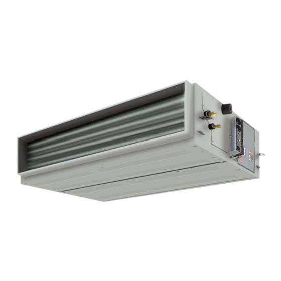
AIR CONDITIONER (SPLIT TYPE)
Installation Manual
Indoor Unit
Model name:
Concealed Duct Type
RAV-SM122BTP-UL
RAV-SM182BTP-UL
RAV-SM242BTP-UL
RAV-SM302BTP-UL
RAV-SM362BTP-UL
RAV-SM422BTP-UL
RAV-SM482BTP-UL
For commercial use
Pour usage commercial
Para uso comercial
1 1 2 8 9 5 0 1 3 8
Installation Manual
1
English
Advertisement
Table of Contents

Related Manuals for Toshiba Carrier RAV-SM122BTP-UL


Summary of Contents for Toshiba Carrier RAV-SM122BTP-UL
- Page 1 AIR CONDITIONER (SPLIT TYPE) 1 1 2 8 9 5 0 1 3 8 Installation Manual For commercial use Indoor Unit Pour usage commercial Para uso comercial Model name: Concealed Duct Type RAV-SM122BTP-UL RAV-SM182BTP-UL RAV-SM242BTP-UL RAV-SM302BTP-UL RAV-SM362BTP-UL RAV-SM422BTP-UL RAV-SM482BTP-UL Installation Manual English...
-
Page 2: Table Of Contents
12 Troubleshooting..........27 work on the air conditioners made by Toshiba Carrier Corporation or, alternatively, he or she has been instructed in such matters by an individual or individuals who have been trained and is thus thoroughly acquainted with the knowledge related to this work. - Page 3 Warning indications on the air conditioner unit Definition of Protective Gear When the air conditioner is to be transported, installed, maintained, repaired or removed, wear protective gloves and ‘safety’ work clothing. Warning indication Description In addition to such normal protective gear, wear the protective gear described below when undertaking the special work detailed in the following table.
-
Page 4: Precautions For Safety
– 3 – • Only a qualified installer or qualified service person is Precautions for safety allowed to undertake work at heights using a stand of 19.7” (50 cm) or more or to remove the intake grille of the indoor unit to undertake The manufacturer shall not assume any liability for the damage work. - Page 5 Installation • Do not move or repair any unit by yourself. Must be done by qualified installer or qualified service person. Special precaution • Suction duct length must be longer than 33.46" (850 mm). should be taken when removing the cover for the unit to avoid •...
- Page 6 – 5 – • When the air conditioner has been installed or relocated, follow the • Under no circumstances the power wire must not be extended. instructions in the Installation Manual and purge the air completely Connection trouble in the places where the wire is extended may so that no gases other than the refrigerant will be mixed in the give rise to smoking and/or a fire.
- Page 7 Explanations given to user CAUTION • Upon completion of the installation work, tell the user where the New refrigerant air conditioner installation circuit breaker is located. If the user does not know where the circuit • This air conditioner adopts the new HFC refrigerant (R410A) breaker is, he or she will not be able to turn it off in the event that which does not destroy ozone layer.
-
Page 8: Accessory Parts
– 7 – Accessory parts Selection of installation place Avoid installing in the following places Accessory parts Select a location for the indoor unit where the cool or warm air will circulate evenly. Avoid installation in the following kinds of locations. Part name Q’ty Shape... - Page 9 Installation under high-humidity atmosphere Installation space (Unit: in (mm)) Reserve sufficient space required for installation or service work. In some case, including the rainy season, The inside of the ceiling may become a high-humidity atmosphere (dew-point temperature: 73.4 °F (23 °C) or higher). 1.
-
Page 10: Installation
– 9 – Installation of hanging bolt Installation of indoor unit Installation • When determining the location of the indoor unit, Treatment of ceiling consider the piping and wiring connection CAUTION The ceiling differs according to structure of building. •... - Page 11 Installation electrical cover 2 holes type Attach the Electrical control box cover to unit. REQUIREMENT In case of group control, electrical cover 1 hole type need to change to electrical cover 2 holes type. Attach the screws 4 parts Remove Electrical control box cover.
-
Page 12: Drain Piping
– 11 – Mounting filter rails and filters Drain piping Mount the filter rail so that the hooks fit into the corresponding holes. CAUTION (Note that the upper and lower filter rails are not identical.) Following the Installation Manual, perform the drain piping work so that water is properly drained. Mount the filter stopper. - Page 13 Gravitational drainage Check the draining In the test run, check that water drain is properly performed and water does not leak from the connecting part of Reattach the drain cap. the pipes. When doing this, also check that no abnormal sounds are heard from the drain pump motor. Check draining also when installed in heating period.
- Page 14 – 13 – Insulation process • As shown in the figure, cover the flexible hose and hose band with the attached insulation up to the bottom of the indoor unit tightly. • Cover the drain pipe tightly with an insulation procured locally so that it overlaps with the attached insulation of the drain connecting section.
- Page 15 Fan characteristics RAV-SM182BTP-UL RAV-SM242BTP-UL RAV-SM122BTP-UL Standard air flow: 395 CFM Standard air flow: 541 CFM Standard air flow: 776 CFM 0.6 in.WG-High tap 0.6 in.WG- High tap 0.6 in.WG-High tap 0.4 in.WG-Mid tap 0.4 in.WG- Mid tap 0.4 in.WG-Mid tap 0.4 in.WG-High tap 0.4 in.WG- High tap 0.4 in.WG-High tap...
- Page 16 – 15 – The concealed duct unit has 7 steps of static pressure (RAV-SM122 ~ 242BTP-UL is 0.12 – 0.6 in. WG, RAV-SM302 ~ 482BTP-UL is 0.12 – 0.8 in. WG) adjustment to meet the installation site requirements / conditions. With these steps there are different speed fan taps associated to select correct air flow.
-
Page 17: Duct Design
Duct design Arrangement (Unit: in (mm)) Referring to the following dimensions, manufacture duct at the local site. SM122, SM182 SM242 SM302, SM362, SM422, SM482 <Under air intake> <Under air intake> <Under air intake> 37.8" 53.6" 26.0" (1359.4) (959.4) (659.4) 3.9"... -
Page 18: Refrigerant Piping
– 17 – Refrigerant piping Evacuation • The sealed gas was sealed at the atmospheric pressure so when the flare nut is removed, therewill no “whooshing” sound: This is normal and is not Perform vacuuming from the charge port of valve of the Connecting refrigerant ... -
Page 19: Electrical Connection
Insulation process Electrical connection Apply insulation for the pipes separately at liquid side and gas side. • For the insulation to the pipes at gas side, be sure to use the material with heat-resisting temperature 248 °F (120 °C) or higher. WARNING •... - Page 20 – 19 – Wiring between indoor unit and outdoor unit Wire connection 1. Figure below shows the wiring connections between the indoor and outdoor units and between the indoor units REQUIREMENT and remote controller. The wires indicated by the broken lines or dot-and-dash lines are provided locally. •...
-
Page 21: Applicable Controls
DN setting Applicable controls External static pressure settings Perform the advanced settings for the air conditioner. Carry out the setting operation while the indoor unit Basic procedure for changing REQUIREMENT is stopped. (Turn off the air conditioning unit before Set up a tap change based upon the external static settings starting the setting operation.) - Page 22 – 21 – Energy saving External static pressure Filter sign setting Set for the energy saving operation: Energy saving When using the wireless remote controller According to the installation condition, the filter sign operation, Set temp. range limit, Return back and To set up the external static pressure, use the DIP switch on the circuit board of the wireless reception part.
- Page 23 Energy saving operation Group control Push the [ MENU] button. Indoor unit data Setting” appears on the screen, then the “ Set for the power saving operation of the air conditioner. CODE No. Data name Simultaneous twin, triple or double twin screen returns to the “Energy saving operation”...
- Page 24 – 23 – [Procedure example] Group control for system of multiple units One remote controller can control maximum 8 indoor units as a group. Manual address setup procedure While the operation stops, change the setup. (Stop the operation of the unit.) ...
- Page 25 46 °F (8 °C) operation Indoor UNIT No. before setup change is displayed. Push the “ unit” [ F1] button to After check of the changed contents, Push select the unit to set. the “ No” [ F2] button to The selected unit changes as follows each finish the setting operation.
-
Page 26: Test Run
– 25 – Wireless remote controller When a test run is not Test run When TEMPORARY button is pushed for 10 performed properly seconds or more, “Pi!” sound is heard and Before test run the operation changes to test run. After approx. •... -
Page 27: Maintenance
Periodic Maintenance Maintenance For environmental conservation, it is strongly recommended that the indoor and outdoor units of the air conditioner in use be cleaned and maintained regularly to ensure efficient operation of the air conditioner. When the air conditioner is operated for a long time, periodic maintenance (once a year) is recommended. <Daily maintenance>... -
Page 28: Troubleshooting
– 27 – Error codes and parts to be checked Troubleshooting Wired Wireless remote controller Confirmation and check remote Sensor block display of controller receiving unit Judging display Main defective parts Parts to be checked / error description conditioner device status Operation Timer... - Page 29 Wired Wired Wireless remote controller Wireless remote controller remote remote Sensor block display of Sensor block display of controller controller receiving unit Judging receiving unit Judging display Main defective parts Parts to be checked / error description conditioner display Main defective parts Parts to be checked / error description conditioner device...
- Page 30 – 29 – Warnings on Refrigerant Leakage Important Check of concentration limit The room in which the air conditioner is to be installed requires a design that in the event of refrigerant 2) When there is an effective opening with the adjacent room for ventilation of leaking refrigerant gas (opening gas leaking out, its concentration will not exceed a set limit.
- Page 31 59-EN 60-EN – 30 –...
- Page 32 144 / 9 Moo 5, Bangkadi Industrial Park, Tivanon Road, Tambol Bangkadi, Amphur Muang, Pathumthani 12000, Thailand 1 1 2 8 9 5 0 1 3 8...