Toshiba RAV-SM564UTP-E Installation Manual
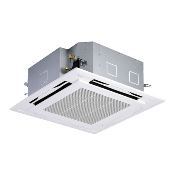
Air conditioner (split type) 4-way cassette type
Hide thumbs
Also See for RAV-SM564UTP-E:
- Service manual (108 pages) ,
- Installation manual (56 pages) ,
- Service manual (108 pages)

Related Manuals for Toshiba RAV-SM564UTP-E


Summary of Contents for Toshiba RAV-SM564UTP-E
-
Page 1: Installation Manual
AIR CONDITIONER (SPLIT TYPE) Installation Manual Indoor Unit For commercial use Model name: 4-way Cassette type RAV-SM564UTP-E RAV-SM804UTP-E RAV-SM1104UTP-E RAV-SM1404UTP-E RAV-SM1604UTP-E English... -
Page 2: Table Of Contents
– 1 – Original instruction Please read this Installation Manual carefully before installing the Air Conditioner. • This Manual describes the installation method of the indoor unit. • For installation of the outdoor unit, follow the Installation Manual attached to the outdoor unit. ADOPTION OF NEW REFRIGERANT This Air Conditioner uses R410A an environmentally friendly refrigerant. - Page 3 Toshiba Carrier Corporation or, alternatively, he or she has been instructed in such matters by an individual or individuals who have been trained and is thus thoroughly acquainted with the knowledge related to this work.
-
Page 4: Precautions For Safety
– 3 – Precautions for safety Warning indications on the air conditioner unit The manufacturer shall not assume any liability for the damage caused by not observing the description of this Warning indication Description manual. WARNING WARNING WARNING ELECTRICAL SHOCK HAZARD General ELECTRICAL SHOCK HAZARD Disconnect all remote... - Page 5 • Carry out the specified installation work to guard against the possibility of high winds and earthquake. If the air Relocation conditioner is not installed appropriately, a unit may topple over or fall down, causing an accident. • Only a qualified installer(*1) or qualified service person(*1) is allowed to relocate the air conditioner. It is dangerous •...
-
Page 6: Accessory Parts
– 5 – Accessory parts Selection of installation place Part name Q’ty Shape Usage WARNING (Hand over to customers) Installation Manual This manual (For other languages that do not appear in this Installation Manual, • Install the air conditioner at enough strong place to withstand the weight of the unit. please refer to the enclosed CD-R.) If the strength is not enough, the unit may fall down resulting in injury. -
Page 7: Installation Space
Installation space When the height of the ceiling exceeds the distance of the item Standard / 4-way in Table as below, the hot air is difficult to reach the floor. Secure the specified space in the figure for installation and servicing. Therefore, it is necessary to change the setup value of the high ceiling switch or discharge direction. -
Page 8: Installation
– 7 – Installation Opening a ceiling and ◆ Treatment of ceiling installation of hanging bolts The ceiling differs according to structure of building. For details, consult your constructor or interior finish REQUIREMENT • Consider the piping / wiring before the unit is hung contractor. - Page 9 ◆ Installation of ceiling opening and Installation of ceiling panel In case of wireless type Level vial (levelness: 5 mm or less) hanging bolt Hanging bolt (Sold separately) Indoor unit The sensor of indoor unit with wireless remote controller can receive a signal by distance within Hanging bolt Install the ceiling panel according to Installation...
-
Page 10: Drain Piping
– 9 – Drain piping Connecting drain pipe Check the draining • Connect a hard socket (locally procured) to the hard In the test run, check that water drain is properly • For length of the traversing drain pipe, restrict to 20 m socket of the attached supplied flexible hose. -
Page 11: Refrigerant Piping
Refrigerant piping • Test water drain while checking the operation sound of the drain pump motor. (If the operation sound changes from continuous Projection margin in flaring: B (Unit: mm) sound to intermittent sound, water is normally CAUTION drained.) Outer dia. of Conventional R410A tool used After the check, the drain pump motor runs,... -
Page 12: Electrical Connection
– 11 – Electrical connection • Use the tightening torque levels as listed in the Open the valve fully following table. Open the valve of the outdoor unit fully. A 4 mm- hexagonal wrench is required for opening the valve. Outer dia. -
Page 13: Wire Connection
Wiring between indoor unit and outdoor unit Wire connection 1. Figure below shows the wiring connections between the indoor and outdoor units and between the indoor units REQUIREMENT and remote controller. The wires indicated by the broken lines or dot-and-dash lines are provided at the locally. •... -
Page 14: Remote Controller Wiring
– 13 – For RAV-SM1603AT-E See the figure on the left for system interconnection wires to the terminal block. WARNING For the synchronous twin and synchronous triple systems, perform the following to conform to EMC standards. System interconnection wire Earth wire ▼... -
Page 15: Applicable Controls
Applicable controls Installing indoor unit on high Each time button is pushed, indoor unit numbers in the control group change ceiling cyclically. Select the indoor unit to change Basic procedure for changing REQUIREMENT settings for. When an indoor unit is installed on a ceiling higher than settings The fan of the selected unit runs and the louvers •... -
Page 16: How To Set Up Swing Type
– 15 – Filter sign setting To select horizontal wind How to set up swing type • About “Dual swing” “Dual” means that louvers 01 and 03 are directed direction According to the installation condition, the filter sign 1. - Page 17 How to set up louver lock How to cancel louver lock Power saving mode Remote controller switch (No swing) monitoring function Set the wind direction to “0000” of the louver lock setup Performing settings of the power saving procedure above.
- Page 18 – 17 – Group control Push button to return to the normal Group control for system of multiple units display. One remote controller can control maximum 8 indoor units as a group. Simultaneous twin, triple or double twin Indoor unit data ▼...
- Page 19 [Procedure example] After check of the changed contents, push button. (Setup is determined.) When Manual address setup procedure 1. Specify CODE No. [12] with TEMP. 1. Specify CODE No. [14] TEMP. buttons. button is pushed, the display disappears buttons. (CODE No. [14]: Group address) While the operation stops, change the setup.
- Page 20 – 19 – 8 °C operation (SDI 4series To recognize the position of the After confirmation, push button to return corresponding indoor unit though the the mode to the usual mode. and DI 4series only) indoor UNIT No. is known When button is pushed, the display disappears and the status becomes the usual stop status.
-
Page 21: Test Run
Test run ◆ Wireless remote controller (RBC-AX32U series) Test run (forced cooling operation) Before test run Wired remote controller REQUIREMENT • Before turning on the power supply, carry out the 2, 4 following procedure. Finish the forced cooling operation in a short time because it applies excessive strength to the air 1) By using 500 V-megger, check that resistance conditioner. -
Page 22: Maintenance
– 21 – Maintenance Cleaning of discharge louver The discharge louver can be removed to clean. 1. Remove the discharge louver. Use a vacuum cleaner to remove dust from CAUTION • Holding the both ends of the discharge louver, the filters or wash them with water. remove the louver sagging the center downward. -
Page 23: Troubleshooting
Troubleshooting ▼ Periodic Maintenance For environmental conservation, it is strongly recommended that the indoor and outdoor units of the air conditioner in use be cleaned and maintained regularly to ensure efficient operation of the air conditioner. When the air conditioner is operated for a long time, periodic maintenance (once a year) is recommended. ... - Page 24 – 23 – Error codes and parts to be checked Wired Wireless remote controller remote Sensor block display of controller receiving unit display Judging Main defective parts Parts to be checked / error description conditioner Wired Wireless remote controller device status remote...
- Page 25 Wired Wireless remote controller remote Sensor block display of controller receiving unit display Judging Main defective parts Parts to be checked / error description conditioner device status Operation Timer Ready Indication Flashing GR GR OR Gas leakage There may be gas leakage from the pipe or Entire Outdoor detected...
- Page 26 TOSHIBA CARRIER (THAILAND) CO.,LTD. 144/9 MOO 5, BANGKADI INDUSTRIAL PARK, TIVANON ROAD, TAMBOL BANGKADI, AMPHUR MUANG, PATHUMTHANI 12000, THAILAND. 1114119201...