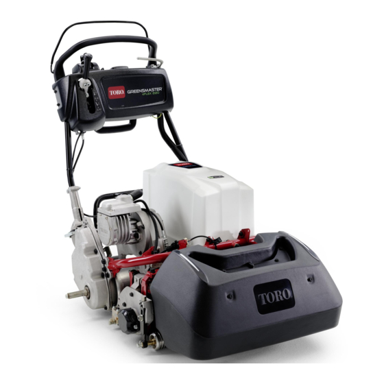
Toro Greensmaster eFlex 2120 Operator's Manual
Traction unit
Hide thumbs
Also See for Greensmaster eFlex 2120:
- Operator's manual (48 pages) ,
- Service manual (312 pages) ,
- Operator's manual (44 pages)

Related Manuals for Toro Greensmaster eFlex 2120


Summary of Contents for Toro Greensmaster eFlex 2120
- Page 1 Form No. 3442-320 Rev A Greensmaster ® eFlex ® 2120 Traction Unit Model No. 04049—Serial No. 400000000 and Up *3442-320* Register at www.Toro.com. Original Instructions (EN)
- Page 2 Whenever you need service, genuine Toro parts, or additional information, contact an authorized Toro distributor and have the model and serial numbers of your product ready.
-
Page 3: Table Of Contents
Contents Servicing the Battery Pack........ 35 Shipping the Battery Pack for Service ....35 Disposing of the Battery........35 Safety ............... 4 Maintaining the Battery Charger ....... 35 General Safety........... 4 Replacing Fuses..........35 Safety and Instructional Decals ......4 Servicing the Traction Interlock Switch.... -
Page 4: Safety
Safety • Do not put your hands or feet near moving components of the machine. • Do not operate the machine without all guards This machine has been designed in accordance and other safety protective devices in place and with ANSI B71.4-2017, IEC 60335-1: 2012, and IEC functioning properly on the machine. - Page 5 decal137-9693 137-9693 1. Electrical shock hazard—stay away from the battery; keep all guards and shields in place. decal139-5613 decal131-3111 139-5613 131-3111 1. Warning—do not discard. 1. Fast 2. Slow decal133-8061 133-8061 decal139-5614 139-5614 1. Warning—read the Operator’s Manual before performing maintenance.
- Page 6 decal121-4685 121-4685 1. EZ-Turn switch 2. On 3. Off 4. Start (machine) decal133-2335 133-2335 3. Thrown object hazard—keep 5. Do not tow the machine. 1. Warning—read the Operator’s Manual; all operators should be trained before bystanders away. operating the machine. 2.
-
Page 7: Setup
Setup Loose Parts Use the chart below to verify that all parts have been shipped. Procedure Description Qty. Target plate Install the target plate. – No parts required Prepare the traction unit (optional). Bolt (3/8 x 3/4 inch) Install the cutting unit to the traction unit. Handle retainer Install the handle retainers. -
Page 8: Installing The Target Plate
Installing the Target Plate Preparing the Cutting Unit For Cutting Unit Models 04251, Parts needed for this procedure: 04252, 04253, and 04254 Only Target plate No Parts Required Procedure Prepare the cutting unit as described in the Procedure cutting unit Operator’s Manual. Position the cutting unit on a flat, level surface. -
Page 9: Installing The Cutting Unit To The Traction
Installing the Cutting Unit to the Traction Unit Parts needed for this procedure: Bolt (3/8 x 3/4 inch) g000483 Figure 7 Procedure 1. Transmission coupling Note: To install the weight rod onto your machine, refer to the installation instructions in your cutting unit Maneuver the machine frame forward until it Operator’s Manual. -
Page 10: Adjusting The Ez-Turn Sensor
Installing the Handle Adjusting the EZ-Turn Retainers Sensor No Parts Required Parts needed for this procedure: Handle retainer Procedure Hairpin cotter Ensure that the machine is on a flat, level surface with the traction drum on the ground. Procedure Loosen the jam nuts on the sensor and adjust the sensor so that 1 thread is visible past the While supporting the handle, remove the cable lower jam nut... -
Page 11: Installing The Transport Wheels
Set the EZ-Turn switch to the O position. Press the wheel locking clip toward the center of wheel and slide the wheel onto the hex shaft Rotate the sensor bracket toward the target plate (Figure 12). until the light on top of the sensor illuminates (Figure 10). -
Page 12: Installing The Production-Year Decal
Installing the Installing the Grass Basket Production-Year Decal Parts needed for this procedure: CE Machines Only Grass basket Parts needed for this procedure: Procedure Production-year decal Grasp the basket by the handle. Guide the basket lip between the cutting unit Procedure side plates and over the front roller (Figure... -
Page 13: Mounting The Battery Charger On A Wall
Breaking in the Machine No Parts Required Procedure Only 8 hours of mowing operation is required for the g032408 Figure 15 break-in period. 1. Pitch-arm contact point Since the first hours of operation are critical to future dependability of the machine, monitor the machine functions and performance closely so that minor difficulties, which could lead to major problems, are noted and can be corrected. -
Page 14: Product Overview
Controls Product Overview g017156 Figure 17 1. EZ-Turn switch 6. Handle 2. Open space for optional 7. InfoCenter LCD display lights 3. Parking-brake latch 8. Key switch 4. Service brake 9. Speed control 5. Operator-presence control g251031 Figure 16 1. Operator-presence control EZ-Turn Switch 2. - Page 15 Service Brake InfoCenter LCD Display The service brake (Figure 18) is located on the left The InfoCenter LCD display shows information about front side of the handle. Pulling back the lever applies your machine and battery pack, such as the current the service brake.
- Page 16 Traction and Reel-Drive Automatic-Motor Brake Engagement Lever The machine is equipped with an automatic-motor brake that prevents it from rolling when the machine The traction and reel-drive engagement lever (Figure is shut off. The motor brake is on whenever the 20) is located on the front right side of the control traction drive is in the N position or you move...
- Page 17 Kickstand The kickstand (Figure 22) is mounted to the rear of the machine. Use the kickstand when you install or remove the transport wheels or the cutting unit. • To use the kickstand to install the transport wheels, lower the kickstand to the ground and step down on the loop while pulling up and back on the lower-center handle (Figure...
-
Page 18: Specifications
Performing Daily To ensure optimum performance and continued safety Maintenance certification of the machine, use only genuine Toro replacement parts and accessories. Replacement Perform the daily maintenance procedures; refer to parts and accessories made by other manufacturers Daily Maintenance Checklist (page 33). -
Page 19: Setting The Machine To Match Turf Conditions
Setting the Machine to Match Turf Conditions Use the following table to set the machine to match turf conditions. Bedbars: Standard and Optional (Flex/eFlex 2120 Machines) Part Number Description Aggressiveness Comments 106-2468-01 Non-Aggressive Less Red, Standard 99-3794-03 Aggressive More Black Bedbars: Standard and Optional (Flex/eFlex 1820 Machines) 110-2282-01 Non-Aggressive... -
Page 20: Adjusting The Handle Height
Adjusting the Handle Adjusting the Handle Angle Height Remove the hairpin cotters from the handle retainers on each side of the machine (Figure 25). Note: The machine is shipped with the handle adjusted to the lowest position. The machine is normally operated with the handle telescoped out to its maximum height. -
Page 21: Checking The Operation Of The Interlock Switches
Adjust the throttle control to the desired position. Tighten the throttle-control fasteners. Install the previously removed console cover. Checking the Operation of the Interlock Switches Service Interval: Before each use or daily CAUTION If the safety interlock switches are disconnected or damaged the machine could g017002 operate unexpectedly, causing personal Figure 27... -
Page 22: Transporting The Machine To The Job Site
Securely fasten the machine to the trailer. Note: You can use the Toro Trans Pro trailer to transport the machine. For instructions on loading the trailer, refer to your trailer Operator’s Manual. Important:... -
Page 23: During Operation
• Use your full attention while operating the • Use only accessories and attachments approved machine. Do not engage in any activity that by The Toro® Company. causes distractions; otherwise, injury or property damage may occur. Slope Safety • Before you turn on the machine, ensure that all drives are in neutral, the parking brake is engaged, •... -
Page 24: Starting The Machine
Releasing the Transmission result in sliding and a loss of braking and steering. The machine can slide even if you stop the drive. If the machine becomes disabled with the motor brake • Remove or mark obstacles such as ditches, holes, on, you can disengage the drum from the transmission ruts, bumps, rocks, or other hidden hazards. -
Page 25: Using The Infocenter Lcd Display
Description Faults The Faults menu contains a list of the recent machine faults. Refer to the Service Manual or your authorized Toro distributor for more information on the Faults menu and the information contained there. Service The Service menu contains information on the machine such as hours of use and battery usage and status. -
Page 26: Operating Tips
(Figure 30). Note: If you inadvertently change the language or contrast to a setting where you can no longer understand or view the display, contact your authorized Toro distributor for assistance in resetting the display. - Page 27 Traction and Reel-Drive Lever Positions Light Conditions 1. N 3. Traction—F EUTRAL ORWARD When operating in low light conditions, use the LED (transport) Light Kit; contact your authorized Toro distributor. 2. Traction—N 4. Traction—F EUTRAL ORWARD reel drive—D reel drive—E ISENGAGE...
-
Page 28: After Operation
Do not store the machine where there is an open plug for 120 VAC operation. For use with 240 V flame, spark, or pilot light, such as on a water circuits, contact your authorized Toro distributor for heater or on other appliances. the correct power cord. -
Page 29: Transporting The Machine
• Do not disassemble the charger. Take the charger For detailed information on shipping the battery pack, to an authorized Toro distributor when service or refer to the Installation Instructions included with the repair is required. Battery Shipping Kit. These instructions are available on www.Toro.com. -
Page 30: Understanding The Battery Charger
Connecting to a Power Source To reduce the risk of electric shock, this charger has a 3-prong grounded plug (type B). If the plug does not fit into the wall receptacle, other grounded plug types are available; contact an authorized Toro distributor. - Page 31 LCD display (Figure 32) 1 digit at a time, starting with the letter E or F (for example, E-0-1-1). To correct an error, refer to Troubleshooting (page 43). If none of these solutions correct the issue, contact an authorized Toro distributor.
-
Page 32: Maintenance
Before you leave the operator’s position, do the following: • If major repairs are ever needed or if assistance is desired, contact an authorized Toro distributor. – Park the machine on a level surface. – Disengage the cutting unit(s). – Ensure that the traction is in neutral. -
Page 33: Recommended Maintenance Schedule(S)
Recommended Maintenance Schedule(s) Maintenance Service Maintenance Procedure Interval • Check the operation of the interlock switches. Before each use or daily • Clean the machine. After each use • Inspect the reel drive belt. Every 1,000 hours • Inspect the transmission bearings. Replace as necessary. •... -
Page 34: Pre-Maintenance Procedures
Pre-Maintenance Lubrication Procedures Greasing the Motor Coupler Disconnecting the Battery Service Interval: Yearly Grease Type: General-purpose grease. Before performing maintenance on the machine, disconnect the machine from the battery pack by Shut off the machine and disconnect the battery pulling the T-handle connector off the main power pack. -
Page 35: Electrical System Maintenance
Shipping the Battery Pack for Service If your battery pack requires service, contact your authorized Toro distributor for assistance. If you must ship the battery pack, obtain the Battery Shipping Kit. This kit contains the proper tape, labeling, and instructions you will need to ship the battery pack. -
Page 36: Servicing The Traction Interlock Switch
Servicing the Mow Sensor If any fuse is blown, replace them with a fuse of the appropriate voltage and amperage (Figure Shut off the machine and disconnect the battery 36). pack. Important: All fuses on the machine are Remove the control panel. rated for 80 V. -
Page 37: Servicing The Brake-Interlock Switch
Servicing the Brake Maintenance Brake-Interlock Switch Adjusting the Shut off the machine and disconnect the battery pack. Service/Parking Brake Remove the console cover. If the service/parking brake slips when operated, Engage the service-brake lever and engage the adjust the cable as follows: parking-brake latch. -
Page 38: Belt Maintenance
Belt Maintenance Using a 16 mm (5/8 inch) wrench, rotate the bearing housing to ensure that it operates freely. Inspecting the Reel Drive Clean any debris from inside the belt compartment and from around the Belt compression spring (Figure 41). Ensure that the compression spring is Service Interval: Every 1,000 hours applying the proper tension on the belt. -
Page 39: Engaging/Disengaging The Transmission-Belt Tensioner
Engaging/Disengaging Controls System the Transmission-Belt Maintenance Tensioner Adjusting the Reel Control The transmission belt is tensioned by a spring-loaded idler pulley. If you must engage or disengage the If the reel control does not properly engage, an belt tension, use a 3/8-inch wrench to rotate the adjustment is required. -
Page 40: Cutting Unit Maintenance
• The reel stopping time must be less than 7 seconds with the reel to bedknife backed off. • Refer to the Service Manual or contact your authorized Toro distributor for further assistance. -
Page 41: Cleaning
Check and tighten all fasteners. Repair or replace any part that is worn or damaged. Paint all scratched or bare metal surfaces with paint available from your authorized Toro distributor. For prolonged storage, follow the battery storage requirements; refer to... -
Page 42: Battery Storage Requirements
Storage Conditions Temperature Requirement or damaged parts. To repair or replace parts, Normal storage conditions -20° to 45°C (-12° to 113°F) contact your authorized Toro distributor for assistance. Extreme heat—1 month or 45° to 60°C (113° to 140°F) less Store the charger with the power supply cord in Extreme cold—3 months or... -
Page 43: Troubleshooting
Code E-0-0-4 1. BMS or battery fault detected 1. Contact an authorized Toro distributor. Code E-0-0-7 1. Battery amp hour limit exceeded 1. Possible causes include poor battery health, very deeply discharged battery,... - Page 44 Notes:...
- Page 45 The Toro Company (“Toro”) respects your privacy. When you purchase our products, we may collect certain personal information about you, either directly from you or through your local Toro company or dealer. Toro uses this information to fulfil contractual obligations - such as to register your warranty, process your warranty claim or to contact you in the event of a product recall - and for legitimate business purposes - such as to gauge customer satisfaction, improve our products or provide you with product information which may be of interest.
- Page 46 While the exposure from Toro products may be negligible or well within the “no significant risk” range, out of an abundance of caution, Toro has elected to provide the Prop 65 warnings. Moreover, if Toro does not provide these warnings, it could be sued by the State of California or by private parties seeking to enforce Prop 65 and subject to substantial penalties.
- Page 47 Countries Other than the United States or Canada Customers who have purchased Toro products exported from the United States or Canada should contact their Toro Distributor (Dealer) to obtain guarantee policies for your country, province, or state. If for any reason you are dissatisfied with your Distributor's service or have difficulty obtaining guarantee information, contact your Authorized Toro Service Center.
- Page 48 4 years Battery Limited Warranty Battery The rechargeable Lithium-Ion battery is warranted to be free from defects in materials and workmanship for a period of 4 years. Over time, battery consumption reduces the amount of energy capacity (Amp-hours) available per full charge. Energy consumption varies due to operating characteristics, accessories, turf, terrain, adjustments, and temperature.