
Related Manuals for Toro 68037G


Summary of Contents for Toro 68037G
- Page 1 Operator’s Manual Ultra Buggy e2500 Model—Serial Range 68037—400000000 and Up 68037G—400000000 and Up *3465-683* A 3465-683A Original Instructions (EN)
- Page 2 (1) this device may not cause harmful interference, and (2) this device must accept any interference received, including interference that may cause undesired operation. Changes or modifications not expressly approved by Toro could void the user’s authority to operate the equipment.
-
Page 3: Table Of Contents
Table of Contents Disclaimers and Regulatory Information....................2 Chapter 1: Introduction........................1–1 Intended Use ............................. 1–1 Getting Help............................1–1 Manual Conventions........................1–2 Safety Alert Classifications......................1–2 Chapter 2: Safety..........................2–1 General Safety ..........................2–1 Safety and Instructional Decals ....................2–1 Chapter 3: Product Overview ...................... - Page 4 Torquing the Wheel Lug Nuts ....................5–10 Drive-Motor Gear Oil Specifications ..................5–10 Changing the Drive-Motor Gear Oil..................5–11 Hydraulic System Maintenance ....................5–12 Hydraulic Fluid Specifications ....................5–12 Checking the Hydraulic Lines ....................5–12 Changing the Hydraulic Fluid ....................5–12 Cleaning............................
-
Page 5: Chapter 1: Introduction
Whenever you need service, genuine Toro parts, or additional information, contact an Authorized G425720 Service Dealer or Toro Customer Service and have the model and serial numbers of your product ready. These numbers are located on the serial plate on your product . -
Page 6: Manual Conventions
Manual Conventions This manual identifies potential hazards and has safety messages identified by the safety- alert symbol, which signals a hazard that may cause serious injury or death if you do not follow the recommended precautions. G405934 This manual uses 2 words to highlight information. Important calls attention to special mechanical information and Note emphasizes general information worthy of special attention. -
Page 7: Chapter 2: Safety
Chapter 2 Safety General Safety • Read and understand the contents of this Operator’s Manual before starting the machine. • Do not operate the machine without all guards and other safety protective devices in place and functioning properly on the machine. •... - Page 8 Decal Part: 125-4967 Lift point decal125-4967 Decal Part: 125-6694 Tie-down location decal125-6694 Decal Part: 133-8061 s_decal133-8061 Decal Part: 144-0275 Batteries are flammable. decal144-0275 Safety: Safety and Instructional Decals Page 2–2 3465-683 A...
- Page 9 Decal Part: 144-0277 Positive terminal Read the Operator’s Manual. Recycle the battery. decal144-0277 Do not dispose improperly. Do not expose to fire. Decal Part: 145-1168 decal145-1168 Warning—shut off the machine and remove the Warning—read the Operator’s Manual. key before leaving the operator’s position. Warning—all operators should read the Operator’s Manual and be trained before operating the Horn...
- Page 10 Decal Part: 145-1170 Warning—read the Operator’s Manual for charging information; do not operate the machine when the machine is charging; disconnect the charging cord before operating the machine. decal145-1170 Decal Part: 145-1173 Traction drive Read the Operator’s Manual for fuse information. Hopper lift cylinder decal145-1173 Decal Part: 145-1175...
- Page 11 Decal Part: 145-1181 Forklift lifting point decal145-1181 Decal Part: 145-1174 Read the Operator’s Manual for battery charging information. Battery charger input specifications decal145-1174 Decal Part: 145-5301 145-5301 Negative battery terminal Decal Part: 145-5338 decal145-5338 Warning—read the Operator’s Manual. Electric shock hazard—do not perform maintenance on the battery.
-
Page 12: Chapter 3: Product Overview
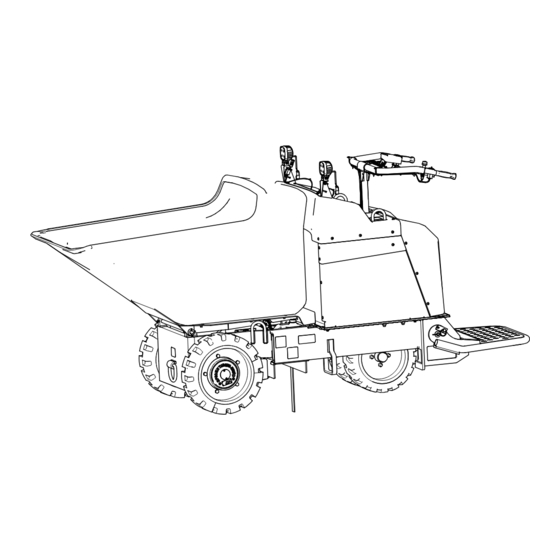
Chapter 3 Product Overview Work lights Handle bars Control panel Electrical service disconnect switch Operator platform Steering tires Hopper Drive tires Anti-static strap G380315 Controls Electrical Service Disconnect Switch Off—to de-energize the machine electrically On—to energize the machine electrically G387210 Product Overview Page 3–1 3465-683 A... -
Page 13: Directional Switch
Directional Switch Drive forward Neutral Drive backward G380320 Dump Controls Dump hopper Lower hopper G380321 Emergency Stop Pull to enable the machine. Note: Turn the key to the then position to continue operating the machine. Push to immediately shut off the machine. -
Page 14: Key Switch
Key Switch Turn the machine off. Turn the machine on. G380323 Light Switch G431514 Throttle Control g357324 Product Overview: Controls Page 3–3 3465-683 A... -
Page 15: Display
Display Display Icon Descriptions Description Icon Menu access Next Previous Scroll down Enter Increase Decrease Exit menu Check PIN entry Parking brake is engaged. Hour meter Battery voltage Battery charge—each solid bar represents the change in 10% increments. 3465-683A Page 3–4 Product Overview: Controls... - Page 16 Display (continued) Display Main Menu Menu Item Description Faults A list of the recent machine faults. Refer to the Service Manual or your Authorized Service Dealer for more information on the faults menu. Service Machine information such as hours of use and other similar numbers. Diagnostics Displays the state of each machine switch, sensor, and control output.
- Page 17 Display (continued) Display Diagnostics Menu Menu Item Description Battery Indicates the inputs and outputs for the battery. Inputs include the current battery voltage; outputs include the battery current and percentage state of charge. Left Motor Indicates the speed and current of the left motor. Right Motor Indicates the speed and current of the right motor.
-
Page 18: Specifications
Discharge height 16.5 cm (6.5 inches) Attachments/Accessories A selection of Toro approved attachments and accessories is available for use with the machine to enhance and expand its capabilities. Contact your Authorized Service Dealer or authorized Toro distributor or go to www.Toro.com... -
Page 19: Chapter 4: Operation
Chapter 4 Operation Before Operation Before Operation Safety Before Operation General Safety • Never allow children or untrained people to operate the machine. Local regulations may restrict the age of the operator. The owner is responsible for training all operators and mechanics. -
Page 20: Performing Daily Maintenance
Before Operation Safety (continued) • Park the machine on a level surface, engage the parking brake (if applicable), and shut off the machine. Wait for all movement to stop and allow the machine to cool before adjusting, servicing, cleaning, or storing the machine. Performing Daily Maintenance Before starting the machine each day, perform the Each Use/Daily procedures listed in the Maintenance Schedule. - Page 21 During Operation Safety (continued) • Do not overload the hopper and always keep the load level when operating the machine. • Avoid operating the machine on loose terrain. Loose terrain could cause the machine to lose traction, affecting steering, stability, and braking. •...
-
Page 22: Starting The Machine
Starting the Machine 1. Ensure that the battery-disconnect switch is in the ON position. 2. Stand on the platform. 3. Insert the key into the key switch and turn it to the ON position. Note: The machine may have difficulty starting under severe cold conditions. When starting a cold machine, keep the machine above -7°C (20°F). -
Page 23: Operator Platform
Operating the Machine (continued) 4. Release the speed control handle to stop the machine. 5. Put the drive controls in the position NEUTRAL and turn the key switch to the position. G380322 Operator Platform You can use the machine with the platform in the up or down position. WARNING The operator platform is heavy and may cause injury when you raise or lower it. -
Page 24: Operating The Hopper
Operator Platform (continued) Raising the Platform Rotate the platform up until it locks into position. G380478 Lowering the Platform 1. Push the platform forward to release pressure on the latch pin. 2. Pull the latch pin out and lower the platform. G388718 Operating the Hopper IMPORTANT... -
Page 25: After Operation
• Do not get the charger wet; keep it protected from rain and snow. • A risk of fire, electric shock, or injury may result from using an accessory not recommended or sold by Toro. • To reduce risk of a battery explosion, follow these instructions and the instructions for any equipment that you intend to use near the charger. -
Page 26: Lowering The Hopper Without Power
After Operation Safety (continued) • Wear appropriate clothing while charging, including eye protection; long pants; and substantial, slip-resistant footwear. • Shut off the machine and wait until the machine has completely powered down before charging. Failure to do this may cause arcing. •... -
Page 27: Raising The Hopper Without Power
Lowering the Hopper without Power (continued) G380311 2. Ensure that the hopper is empty. 3. Remove the bottom cover and place a large drain pan under the hydraulic power unit. 4. Remove the caps off of the hoses to the lift cylinder and allow the fluid to drain. -
Page 28: Haul The Machine
Raising the Hopper without Power (continued) 5. Disconnect the hose fittings and allow the fluid to drain into the pan. Note: Dispose of the used fluid at a certified recycling center. 6. Install the caps on the hydraulic hoses to prevent contamination. - Page 29 Haul the Machine (continued) Full-width ramp in stowed position Ramp is at least 4 times as long as the height of the trailer or truck bed to the ground H = height of the trailer or truck bed to the ground Trailer G229507 Loading the Machine...
- Page 30 Haul the Machine (continued) IMPORTANT Do not use the tie-down loops to lift the machine. G388893 Unloading the Machine 1. Lower the ramp(s). 2. Lower the operator platform. 3. Drive the machine forward down the ramp. Operation: After Operation Page 4–12 3465-683 A...
-
Page 31: Chapter 5: Maintenance
• Use the cylinder lock to secure the hopper in the raised position. • Never tamper with safety devices. • To ensure safe, optimal performance of the machine, use only genuine Toro replacement parts. • Seek immediate medical attention if fluid is injected into skin. Injected fluid must be surgically removed within a few hours by a doctor. -
Page 32: Recommended Maintenance Schedule
• Keep the machine clean to minimize hazards and make inspecting the machine for servicing easier. • Ensure that the extension cord plugs are in good condition and are not hot from operation. Do not use a damaged or worn extension cord. Recommended Maintenance Schedule Maintenance Qty Description... -
Page 33: Pre-Maintenance Procedures
Pre-Maintenance Procedures Retrieving a Machine In an emergency, you can push or tow the machine. Note: Do not tow the machine on a slope; the wheels will spin freely when you remove the gear. 1. Chock the wheels. 2. Remove the gearbox cover. G388719 3. -
Page 34: Lifting The Machine
Lifting the Machine Lifting the Machine with a Forklift IMPORTANT Ensure that the hopper is empty before lifting the machine. 1. Place the platform in the raised position. 2. Lift the machine using the side or rear pockets. G380480 Lifting the Machine with a Hoist IMPORTANT Ensure that the hopper is empty before lifting the machine. -
Page 35: Using The Cylinder Lock
Using the Cylinder Lock Installing the Cylinder Lock 1. Park the machine on a level surface, move the motion-control levers to the N EUTRAL LOCK position, and fully raise the hopper. 2. Remove the 2 cotterless pins securing the cylinder lock to the machine. G380311 3. -
Page 36: Lubrication
Lubrication Greasing the Machine Grease Type: General-purpose grease. Note: Remove the blue protection caps, if applicable, before greasing and replace when finished. 1. Park the machine on a level surface. 2. Shut off the machine. 3. Clean the grease fittings with a rag. 4. -
Page 37: Electrical System Maintenance
Electrical System Maintenance Checking the Anti-Static Strap 1. Park the machine on a level surface, lower the hopper, shut off the machine, and remove the key. 2. Check the anti-static strap and replace it if it is worn or missing. G388771 Battery Service Note:... - Page 38 Battery Service (continued) temperature exceeds the range specified in the Battery Storage Requirements, page 6– IMPORTANT Temperatures outside of this range will damage your batteries. High temperatures during storage, especially at a high state of charge, reduces the life of the batteries.
- Page 39 Battery Service (continued) IMPORTANT Charge the machine in temperatures ranging from 0° to 45°C (32° to 113°F). The onboard charger will not function in temperatures outside of this range. 1. Park the machine in the designated location for charging. 2. Shut off the machine and remove the key. 3.
-
Page 40: Drive System Maintenance
• Clean the charger cord with a slightly damp cloth after each use. • Coil the cord when not in use. • Periodically examine the cord for damage, and replace it when necessary with Toro- approved parts. Drive System Maintenance Inspecting the Tires Inspect tires for cuts, slashes, or bulges. -
Page 41: Changing The Drive-Motor Gear Oil
Changing the Drive-Motor Gear Oil 1. Start the machine and drive it for 5 minutes. Note: This warms the gear oil so that it drains better. 2. Park the machine on a level surface so that a drain plug on the front motor is in the 6 o’clock position. -
Page 42: Hydraulic System Maintenance
Hydraulic System Maintenance Hydraulic Fluid Specifications Hydraulic-Fluid type Mobil ATF Dexron Hydraulic fluid capacity 3.03 L (3.2 US qt) The machine hydraulic tank is filled at the factory with approximately 3.03 L (3.2 US qt) of hydraulic fluid. Checking the Hydraulic Lines Check the hydraulic lines for leaks, loose fittings, kinked lines, loose mounting supports, wear, and deterioration. -
Page 43: Cleaning
Changing the Hydraulic Fluid (continued) 9. Fill the hydraulic tank with the specified fluid. 10. Install the cap. G426593 Cleaning Removing Debris 1. Park the machine on a level surface, shut off the machine, and remove the key. 2. Clean any debris from the machine. IMPORTANT Blow the dirt out rather than wash it out. - Page 44 Washing the Machine (continued) • Grease all grease points after washing. Maintenance: Cleaning Page 5–14 3465-683 A...
-
Page 45: Chapter 6: Storage
Chapter 6 Storage Storage Safety Park the machine on a level surface, engage the parking brake (if applicable), shut off the machine, and remove the key. Wait for all movement to stop and allow the machine to cool before adjusting, servicing, cleaning, or storing the machine. Preparing the Machine for Storage Over 30 Days 1. - Page 46 IMPORTANT Temperatures outside of these ranges will damage your batteries. The temperature that the batteries are stored at will affect their long-term life. Storage for long periods of time at extreme temperatures will reduce the battery life. For temperatures above 25°C (77°F), only store the machine for the appropriate amount of time indicated in the table.
-
Page 47: Chapter 7: Troubleshooting
Chapter 7 Troubleshooting The machine does not drive. Possible Cause Corrective Action The machine has been inactive for more Set the drive control in the position NEUTRAL than 30 seconds and is in sleep mode. and back to the preferred direction. One or more of the electrical connections Check and tighten any loose connections. - Page 48 The steering is not working properly. Possible Cause Corrective Action The steering needs to be calibrated. Use the display to calibrate the steering system. The steering linkage needs to be adjusted. Check the steering linkage assembly for loose or missing hardware. The hopper is not functioning properly.
-
Page 49: California Proposition 65 Warning Information
Toro has chosen to provide consumers with as much information as possible so that they can make informed decisions about the products they buy and use. Toro provides warnings in certain cases based on its knowledge of the presence of one or more listed chemicals without evaluating the level of exposure, as not all the listed chemicals provide exposure limit requirements. - Page 50 Notes:...
- Page 51 Notes:...