Table of Contents
Advertisement
Quick Links
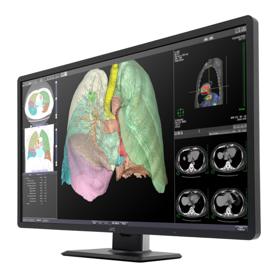
32-inch (81. 3 cm) Color LCD Monitor
Instruction Manual
Model: CL-R813BN0UA
CL-R813BN0EA
Important
This instruction manual contains important information on how to use the product.
Please make sure to read the safety precautions first and keep this manual in a safe and easily
accessible place for future reference.
B5A-4312-00
Advertisement
Chapters
Table of Contents

Related Manuals for JVC CL-R813


Summary of Contents for JVC CL-R813
- Page 1 32-inch (81. 3 cm) Color LCD Monitor Instruction Manual Model: CL-R813BN0UA CL-R813BN0EA Important This instruction manual contains important information on how to use the product. Please make sure to read the safety precautions first and keep this manual in a safe and easily accessible place for future reference.
- Page 2 * All other products and company names are trademarks of their respective owners. - 2 - ENGLISH...
-
Page 3: Table Of Contents
Contents Before use ............................4 Safety precautions ........................15 Product security .........................19 Package contents ........................20 Features ............................21 Names and functions of parts .....................22 Connecting the cables ......................24 Adjusting the monitor angle ....................26 Monitor information ........................27 Reference ............................32 Operating Principle ........................32 Attaching an arm stand ......................33 Anti-Theft security slot ......................34 How to change the fuse ......................35 Cable management ........................36... -
Page 4: Before Use
Before use Thank you for purchasing our color LCD CL-R813. Please read this manual carefully for proper use. For your safety This manual contains important information on how to use the product. Please make sure to read the safety precautions first and keep this manual in a safe and easily accessible place for future reference. - Page 5 receiver is connected. ● Consult your dealer or an experienced radio/TV technician for help. FCC Warning To assure continued FCC compliance, the user must use a grounded power supply cord and the provided shielded video interface cable with bonded ferrite cores. Also, any unauthorized changes or modifications to this monitor would void the user’s authority to operate this device.
- Page 6 Warning ● This apparatus must be earthed because of Class I equipment. ● This apparatus is not a patient contact equipment. ● When using at 240 V in the United States, supply must be from center-tapped, 240 V, single phase circuit. ●...
- Page 7 Guidance and manufacturer’s declaration – electromagnetic emissions The model CL-R813 is intended for use in the electromagnetic environment specified below. The customer or the user of the model CL-R813 should assure that it is used in such an environment. Electromagnetic environment...
- Page 8 The model CL-R813 is intended for use in the electromagnetic immunity environment (Home healthcare environment defined in IEC 60601-1-2) specified below. The customer or the user of the model CL-R813 should assure that it is used in such an environment.
- Page 9 The model CL-R813 is intended for use in the electromagnetic immunity environment (Home healthcare environment defined in IEC 60601-1-2) specified below. The customer or the user of the model CL-R813 should assure that it is used in such an environment.
- Page 10 RF transmitters, an electromagnetic site survey should be considered. If the measured field strength in the location in which the model CL-R813 is used exceeds the applicable RF compliance level above, the model CL-R813 should be observed to verify normal operation.
- Page 11 RF communications equipment and the model CL-R813 The model CL-R813 is intended for use in an electromagnetic environment in which radiated RF disturbances are controlled. The customer or the user of the model CL-R813 can help prevent...
- Page 12 The model CL-R813 is intended for use in an electromagnetic environment in which radiated RF disturbances are controlled. The customer or the user of the model CL-R813 can help prevent electromagnetic interference by maintaining a minimum distance between portable and mobile RF communications equipment (transmitters) and the model CL-R813 as recommended below, according to the maximum output power of the communications equipment.
- Page 13 Label Please read the label containing warnings and cautions carefully before use. Important ENGLISH - 13 -...
- Page 14 Explanation of symbols These following symbols and labels indicate meanings as below. Caution Mark Indicates the monitor is approved according to the UL & c-UL regulations This device complies with the requirements of the European Medical Device Regulation (EU) 2017/745 (“MDR”) Indicates this device complies with the requirements of The Medical Devices Regulations 2002 (SI 2002 No 618,...
-
Page 15: Safety Precautions
Safety precautions This manual contains important warnings and information to prevent potential personal injury and property damage. The symbols and signs used in this manual and their meanings are as follows. Symbols Indicates a hazard which, if not avoided, could result in death or serious injury. - Page 16 Warning Do not disassemble, repair, or alter the monitor. It could cause fire, electric shock, or injury. Servicing of such a monitor may be refused. Or a fee may be charged even within the warranty period. Ask your dealer for repairs. Do not continue using the monitor when failure or abnormality is found.
- Page 17 If liquid or any foreign object enters inside, turn off and unplug the monitor immediately. Continual use could cause fire or electric shock. Consult your dealer. To avoid a lighting strike, stop using the monitor during thunder. It could result in electric shock. Make sure to use the supplied power cable.
- Page 18 Avoid a place subject to • Magnetic fields • Vibrations • Corrosive gases • Electrostatic charge It could cause the monitor to fail. Do not use the monitor with condensation on the surface. It could cause the monitor to fail. Condensation forms when the monitor is moved into a warm room from a cold place.
-
Page 19: Product Security
Please be advised that the following symptoms may occur due to the nature of LCDs. They are not failures. • During use in cold environments, “streaking” may occur or images may appear dark. • Depending on use conditions such as temperature, spots or unevenness in luminance or color may be observed. -
Page 20: Package Contents
Package contents Please check if the following items are included in this product package. If any item is missing, contact your dealer for replacement. Don’t use the power cord packaged with this product for other electronics. Note Monitor Power cord (3.0 m) □... -
Page 21: Features
Features ● 32” 8MP high-definition Color LCD panel 32” (diagonal 81.3 cm) LCD panel provides clear display of images high resolution of 8MP (3840 × 2160). ● Daisy-chain via DisplayPort Implemented DisplayPort with 10 bit depth color and achieved 1.073 billion simultaneous color with 10 bit input. -
Page 22: Names And Functions Of Parts
Names and functions of parts ① ② ⑨ ⑧ ⑦ ⑥ ⑤ ④ ③ Key-1–4 ︓ OSD Control ■ ① Ambient light sensor ② LCD luminance sensor ③ LED Indicator Power Mode Power off Green Normal Power management on Orange ④... - Page 23 15 14 13 Human presence sensor: When leaving your seat, the status of the monitor ⑨ automatically switches into “Stand-by” due to “Human presence sensor”. Main power switch_POWER: Main power supply switch. ⑩ ⑪ AC inlet_AC IN: Connect the supplied Power cord. ⑫...
-
Page 24: Connecting The Cables
Connecting the cables Turn off the computer. DisplayPort-screen: Connect “DisplayPort_IN1” or “DisplayPort_IN2” on this monitor to “DisplayPort” output on your computer with the supplied DisplayPort cable. DVI-D-screen: Connect the supplied DVI-D cable to the “DVI-D” port on this product and the “DVI-D” port on the computer. - Page 25 How to setup multiple monitors in daisy-chain Please connect multiple monitors together using DisplayPort as below. Not support Connect to “DisplayPort_IN2” “DisplayPort_IN1” To the DisplayPort output of the computer DisplayPort cable DisplayPort cable ENGLISH - 25 -...
-
Page 26: Adjusting The Monitor Angle
Adjusting the monitor angle The monitor turns 45 degrees sideways, 5 degrees downward, and 20 degrees upward. Hold the monitor with both hands and adjust the angle slowly. 20 degrees 45 degrees 45 degrees 5 degrees Caution Be careful not to pinch your fingers when adjusting the panel angle. -
Page 27: Monitor Information
Monitor information Operation Key Guide “Operation Key Guide” is not displayed on the screen in the default setting. “Operation Key Guide” appears when pressing any one of OSD control keys (1–4) or the stand-by key. Refer to the list below regarding linked setting per each OSD control keys. It disappears after twenty seconds when no operation is done. - Page 28 Function list of OSD adjustment Default LEVEL 1 LEVEL 2 LEVEL 3 LEVEL 4 DESCRIPTION Exit Exit Adjust the brightness Backlight of screen Config1 * Adjust the contrast of Contrast images Exit Adjust the brightness Backlight of screen Config2 Adjust the contrast of Contrast images Exit...
- Page 29 Default LEVEL 1 LEVEL 2 LEVEL 3 LEVEL 4 DESCRIPTION Exit Exit PIP / PbyP Turns off PIP & PbyP OFF * function PIP ON POSITION Shown PIP window PbyP ON Layout Shown PbyP window Top-Right * Select sub POSITION Bottom-Right of PIP (available when POSITION...
- Page 30 DP1.2 * DisplayPort Setting Exit Set up the power of DP POWER On * DisplayPort on power management Model CL-R813 Shown model name Lxxxxxxxxx Shown serial number Source Shown the information xxx.xkHz / of the selected signal Fh / Fv xx.xHz Shown version of FW ver.
- Page 31 Power save mode: high Stand-by ― ― Stand-by mode Main switch OFF ― ― ― Configuration Setting CL-R813 has the following five Configuration settings saved as factory defaults before shipping. Luminance (cd/m Configuration Color Gamma Max. Min. Config1 7500 K DICOM GSDF...
-
Page 32: Reference
Reference Power save function The monitor enters into power save mode after idling for a certain period of time to reduce power consumption. Refer to the computer instruction manual on how to set it. Digital input This monitor supports digital signal. It is normal for noise to occur during startup, shutdown, and/or at switching resolutions. -
Page 33: Attaching An Arm Stand
Attaching an arm stand The tilt stand is interchangeable with commercially available arms that: • Come with a mount plate with 4 slotted screw holes at 115 mm 100 mm × 100 mm, and 100 mm • Bear the total weight of the LCD panel (without the stand) and the cables connected to it. -
Page 34: Anti-Theft Security Slot
Anti-Theft security slot This monitor has a built-in Kensington Security Slot by ACCO Brands Corporation. Please purchase the MicroSaver lock at PC supply stores separately. * “Kensington” and “MicroSaver” are registered trademarks of ACCO Brands Corporation. - 34 - ENGLISH... -
Page 35: How To Change The Fuse
How to change the fuse Note for AC INLET with fuse AC Inlet has a built-in fuse. When replacing the fuse, be sure to use only a correctly rated approved type, re-fit the fuse cover. How to replace the fuse Open the fuse compartment with the blade screwdriver, and replace the fuse. -
Page 36: Cable Management
Cable management Please use the cable hole when plugging in the computer and monitor so that cables will be organized. Cable hole Cable - 36 - ENGLISH... -
Page 37: Supported Signals
Supported signals Table list of the supported signal timing It may not be displayed normally when selecting other than the timing shown in the table below. Vertical Frequency Resolution DisplayPort DVI-D [Hz] 720 × 400 ✓ ✓ 640 × 480 ✓... -
Page 38: Connector Pin Assignment
Connector pin assignment DVI 24-pin (female) connector for DVI signals Pin # Signal Pin # Signal TMDS Data 2- TMDS Data 3+ TMDS Data 2+ +5V Power TMDS Data 2/4 Shield TMDS Data 4- Hot Plug Detect DVI-D TMDS Data 4+ TMDS Data 0- DDC Clock TMDS Data 0+... -
Page 39: Technical Specification
Technical specification Item CL-R813BN0EA/CL-R813BN0UA 32-inch (81.3 cm), color, TFT, Anti-glare, IPS Pixel pitch (H × V) 0.1845 × 0.1845 mm Display area (H × V) 708.48 (H) × 398.52 (V) Pixel (H × V) 3840 × 2160 8 bit: 16.77 million Display colors 10 bit: 1.073 billion Backlight... - Page 40 External dimensions r single screen) 196.5 Unit: mm - 40 - ENGLISH...
-
Page 41: Hardware / Software Compatibility
CAL-016 JVCKENWOOD Calibrator-T4 (external sensor) are included. Utility Disk PSW22-295x JVCKENWOOD Attached to the product CL-R190 CL-R211 Connect to the output port LCD Monitor CV-F238 JVCKENWOOD of CL-R813 as a secondary CL-S200 monitor MS-S200 Windows10 Microsoft ENGLISH - 41 -... -
Page 42: Performance Specifications
Performance specifications (Summary of physical laboratory testing) Test items Specifications Pixel defects (maximum counts, allowed defect ISO 13406-2: Class II types, and locations) By visible check of AAPM-TG18, no ringing, Artifacts ghosting, image sticking Level: Rise, Fall (msec (Typ.)) 0–100 %: 7.0, 6.3 Temporal response 5–95 %: 8.2, 6.4 10–90 %: 9.0, 6.8... -
Page 43: When A Failure Is Suspected
When a failure is suspected... Symptom Cause and Solution • Make sure the monitor AC power cord is plugged. The monitor won’t turn on! P24 ) (The LED indicator is off.) • Check if the monitor is turned on. • Check if cables are connected correctly. P24 )... -
Page 44: Cleaning The Monitor
Cleaning the monitor ● When cleaning the monitor, remove the Power cord from the monitor and the wall outlet for your safety. ● Wipe off dust on the cabinet with a soft cloth, and use a cloth lightly moistened with a mild detergent, ethanol or isopropyl alcohol to remove grease. -
Page 45: After-Sales Service
After-sales service Warranty Consult your dealer about the warranty. Requesting repair • Read “When a failure is suspected...” ( P 43 ) carefully and check if the problem solves. • If the problem remains, stop using the monitor, unplug it, and consult your dealer. Do not try to repair yourself. -
Page 46: Disposal Of Electrical And Electronic Equipment
Disposal of Electrical and Electronic Equipment Information on Disposal of Old Electrical and Electronic Equipment and Batteries (Applicable for countries that have adopted separate waste collection systems) Products and batteries with the symbol (crossed-out wheeled bin) cannot be disposed as household waste. Old electrical and electronic equipment and batteries should be recycled at a facility capable of handling these items and their waste byproducts. - Page 47 CL-R813 Instruction Manual October 2022 Edition Instruction Manual Notes for the • No part of this manual, whether partly or wholly, may be reproduced or copied without authori- zation. • The content of this manual is subject to change without notice.
- Page 48 3-12, Moriya-cho, Kanagawa-ku, Yokohama-shi, Kanagawa 221-0022, JAPAN Printed in Japan © 2022 JVCKENWOOD Corporation - 48 - ENGLISH...
- Page 49 32 型 (81.3 cm) カラー液晶モニター 取扱説明書 Model: CL-R813BN0JA この取扱説明書をよくお読みいただき、正しくお使いください。 また、ご使用前に必ず 「安全上の注意」を読んで正しくお使いください。 「取扱説明書」はできる限り身近なところで大切に保管してください。 - 1 - 日本語...
- Page 50 * 記載されている会社名および商品名は各社の登録商標または商標です。 - 2 - 日本語...
- Page 51 もくじ ......................4 はじめに ....................9 安全上の注意 ...............13 製品セキュリティに関して ..............14 付属品を確認してください ....................15 製品の特長 ..................16 各部の名称と働き ....................18 接続のしかた ................. 20 モニターの角度調整 ....................... 21 操作方法 ....................... 26 参考 ............27 市販のアームを取り付けるときは ..........28 盗難防止セキュリティロックスロット ................... 29 ヒューズの交換 ................30 ケー ブルマネジメント ......................31 対応信号...
-
Page 52: はじめに
はじめに このたびは、当社のカラー液晶モニターをお買い上げいただき、誠にありがとうございます。 本書をよくお読みになり、正しくお使いいただくようお願いいたします。 安全にお使いいただくために 本書には、本製品をお使いいただくための重要な情報が記載されています。 本製品をお使いになる前に、 「安全上の注意」をよくお読みになり、ご理解された上で正しくお 使いください。 また、本書は、本製品の使用中にいつでも参照できるように大切に保管してください。 使用目的 この製品は訓練された医療従事者により使用される製品です。 保証書について 保証書は内容をよくお読みの上、必要事項を記入して大切に保管してください。 修理をするときには、必ず保証書をご用意ください。 本製品を輸出する際のご注意 本製品は、 日本国内仕様です。 本製品を日本国外に輸出する際は、 事前に製品に関する営業窓口にご相談頂き、 輸出者の責任 において、 最終仕向地の関連法令を遵守し、 必要な手続きを行ってください。 海外の法令及び規制への適合について、 当社では責任を負いかねます。 責任制限 ●火災、地震、第三者による行為、その他の事故、使用者の故意または過失、誤用、その他異 常な条件下での使用により生じた損害に関して、当社は一切責任を負いません。 ●本製品の使用または使用不能から生ずる付随的な損害 (事業利益の損失、事業の中断、記憶 内容の変化、消失など)に関して、当社は一切責任を負いません。 ●分解や改造をした場合、当社は一切責任を負いません。 ●取扱説明書で説明された以外の使い方によって生じた損害に対して、当社は一切責任を負いま せん。 ●接続機器との組み合わせによる誤動作などから生じた損害に対して、当社は一切責任を負いま せん。 ●本製品の使用のため当社より供給されたソフトウェアの使用により発生したいかなる損害 (期 限にかかわるもの、ビジネス上の、利益の減少および遅延や情報にかかわるもの、その他、 金銭上の不利益)が、たとえその発生が当方において予想されたとしても、当社は一切責任を 負いません。... - Page 53 (VCCI) について 電波障害自主規制 この装置は、クラスB機器です。この装置は、住宅環境で使用することを目的としていま すが、この装置がラジオやテレビジョン受信機に近接して使用されると、受信障害を引 き起こすことがあります。取扱説明書に従って正しい取り扱いをしてください。 VCCI-B JIS C 61000-3-2 適合品 JIS C 61000-3-2 に適合しております。 本製品は、高調波電流規格 瞬時電圧変動について 本製品は、落雷などによる電源の瞬時電圧低下に対し不具合を生じることがあります。電源の 瞬時電圧低下対策としては、交流無停電電源装置等を使用されることをお薦めします。 注意 ・ 警告表示について 本製品の背面には、注意、警告表示があります。 お使いになる前に、内容をよく読んで安全にお使いください。 - 5 - 日本語...
- Page 54 電源コードの重要情報 下記の表にしたがい、 この表示を備えている電源コードを使用してください。 もしも、製品に電源コードが付属されていない場合は、購入元にお問い合わせください。 その他の国で使用する場合、 コンセントの交流電圧と一致した、 その国の安全基準によっ て認証されている電源コードをご使用ください。北米では医用モニターにはホスピタル グレードの電源コードを使用しなければなりません。 / カナダ 国 米国 欧州 日本 プラグ形状 または VDE 、 Demko 、 UL / CSA 標準 Nemko 、 BSI 等 電圧 注記︓この製品は、購入された国でのみ修理サービスを受けることができます。 - 6 - 日本語...
- Page 55 記号表示について 各表示には次のような意味があります。 一般注意︓特定しない一般的な注意を示しています。 UL 及び c-UL に準拠していま 感電や火災に関しては、 す。 医療機器規制に適合していることを示します。 2002 (SI 2002 No 618, このデバイスが医療機器指令 ) (UK MDR 2002) の要件に適合し およびその修正版 ていることを示しています。 FCC )の規格に適合していること 米連邦通信委員会 ( を示しています。 VCCI 協会のクラスB情報技術装置です。 この装置は、 EMC 規格に適合しているマークです。 オセアニア諸国の WEEE 指令マークです。 欧州の MANUFACTURER 」の記号です。 「 AUTHORIZED REPRESENTATIVE IN THE 「...
- Page 56 安全にお使いいただくための絵記号について ここでは、お客様や他の人々への危害、財産への損害を未然に防ぎ、本製品を安全に正しくお使 いいただくための注意事項を記載しています。 その表示と意味は次のようになっています。 ■絵表示について 警告 この表示を無視して誤った取り扱いをすると、人が死亡また は重傷を負う可能性が想定される内容を示しています。 この表示を無視して誤った取り扱いをすると、人が障害を負 注意 う可能性が想定される内容、および物的損害のみの発生が 想定される内容を示しています。 ■絵記号の意味 で示した記号は警告、注意を促す事項があることを告げるものです。 記号の中には、具体的な警告内容が描かれています。 例) 「感電注意」を表す絵記号 で示した記号は、してはいけない行為 (禁止行為)です。 記号の中には、具体的な禁止内容が描かれています。 例) 「分解禁止」を表す絵記号 で示した記号は、必ずしたがっていただく内容であることを告げるも のです。 記号の中には、具体的な指示内容が描かれています。 例) 「電源プラグをコンセントから抜いてください」を表す絵記号 ■本文中の記号について 使用前に必ず読んでいただきたい内容を記述しています。 お使いになるときに注意していただきたいことや、してはいけないことを記 述しています。 操作に関することを記述しています。必要に応じてお読みください。 本書内の参照ページを記述しています。 - 8 - 日本語...
-
Page 57: 安全上の注意
安全上の注意 警告 本製品を分解・修理・改造はしないでください。 火災、感電、けが、故障の原因となります。 修理・点検は、お買い求めの販売店に依頼してください。 分解や改造をした場合、修理をお断りしたり、保証期間であっても有償修理とな 分解禁止 る場合があります。 故障した状態や異常のまま使用しないでください。 そのまま使用を続けると火災や感電の原因になります。 禁止 ( 液体 ) には、触れないでください。 画面が破損して漏れた液晶 ( 液体 ) が漏れることがあります。液晶に触れ 液晶パネルを破損した場合、液晶 たり、 口に入れたりしないでください。 中毒や皮膚がかぶれる原因になります。 誤っ て目や口に入った場合は、すぐに流水で洗浄し、医師に相談してください。皮膚 接触禁止 や衣服に付着したときは、アルコールなどで拭き取り、水洗いしてください。液 晶には刺激物質が含まれています。 本体の上にものを置いたり、かぶせないでください。 そのまま使用を続けると故障や火災の原因になります。 禁止 ケーブルの上にものを置いたり、かぶせないでください。 そのまま使用を続けると故障や火災の原因になります。 禁止 濡れた手で本製品を取り扱わないでください。 感電や本製品の故障の原因になります。 ぬれ手禁止 煙が出たり変な臭いや音がしたら、すぐに本製品のメイン電源スイッチを切り、 電源プラグをコンセントから抜いてください。 そのまま使用を続けると火災や感電の原因となります。... - Page 58 機器の改造はできません。 禁止 製造元の許可なしにこの機器を改造しないでください。 禁止 この機器を改造した場合は、機器の安全な使用を継続するために、適切な検査 とテストを実施する必要があります。 禁止 感電の危険を避けるため、この装置は保護接地された電源にのみ接続する必要 があります。 禁止 AC 電源インレットは、ディスコネクト装置とみなされます。 禁止 二重極、ニュートラルヒューズ。修理の前に主電源を切ってください。 禁止 電源コードは必ず本製品付属のものを使用してください。 付属の電源コードを他の機器に使用しないでください。 付属品以外のものを使用した場合、発煙、発火など故障の原因となります。 厳守 AC100 – 240 V 本製品は 専用です。指定以外の電圧で使用しないでください。 指定以外の電圧で使用した場合、発煙、発火など故障の原因となります。 厳守 ( 接地 ) をしてください。 電源コードのアース接続 故障や漏電のときに感電の原因となります。 2P プラグの場合、アース接続は必ず電源プラグをコンセントにつ 電源コードが なぐ前に行ってください。また、アース接続をはずす場合は、必ず電源プラグを 厳守 コンセントから抜いてから行ってください。 電源プラグの接続に関しては以下に注意してください。 ・電源プラグを抜くときはプラグ部分を持つ。...
- Page 59 梱包用のビニール袋は子供の手の届かない場所に保管してください。 梱包用のビニール袋をかぶったりすると、窒息の原因になります。 厳守 注意 本製品は、屋内に設置してください。 本製品は、屋外・船舶・車載仕様ではありません。 厳守 風通しの悪い場所、ほこり、湿気の多いところ、油煙・湯気の当たる場所には 設置しないでください。 火災・感電・故障の原因になります。 禁止 不安定な場所に置かないでください。 落下・転倒によりけがや故障の原因になります。 禁止 直射日光が当たる場所や熱器具の近くに置かないでください。 キャビネットや部品などに悪影響を与え、 発熱 ・ 発火の原因になることがあります。 禁止 正しい取扱いをしている場合でも、電波の状況によりラジオやテレビの受信に 影響をおよぼすことがあります。 このようなときには、次の点にご注意ください。 ・本機とラジオ、テレビを十分離してご使用ください。 厳守 ・本機とラジオ、テレビを別のコンセントに接続してください。 液晶パネル面を強く押したり、ひっかいたり、上にものを置いたりしないでくだ さい。 干渉縞が発生するなど表示異常を起こしたり、パネルに傷が付いたりして液晶 禁止 パネル故障の原因になります。 次のような場所に設置しないでください。 ・強い磁界の発生する場所 ・振動の発生する場所 ・腐食性のガスが発生する場所 ・静電気の発生する場所 禁止 故障の原因となります。 本製品は、結露したまま使わないでください。 本製品を寒い部屋から暖かい部屋に移動すると、表面や内部が結露する場合が あります。必ず結露がなくなってからお使いください。そのまま使うと故障の原...
- Page 60 液晶モニターについて 残像の原因となる場合がありますので、長時間静止画像を表示しないでください。 残像とは、長時間同じ静止画像を表示して、表示画面を変えたときに前の画面 表示が影のように残る現象です。 禁止 画面の焼き付き防止のため、スクリーンセーバー機能を使用してください。 液晶パネルは、同じ画面を長時間表示していると画面の焼き付きを起こします。 スクリー ンセーバー機能を使ったり、モニターの電源設定をスタンバイ設定にし 厳守 て焼き付き防止を図ってください。 液晶モニターの場合、次のようなことがありますので、ご注意ください。 ・寒い所でご使用になると、画像が尾を引いて見えたり、画面が暗く見えたりす ることがありますが、故障ではありません。 温度が上がると元に戻ります。 ・本製品は、表示する条件により微少な斑点およびムラが目立つこともあります が、故障ではありません。 注意 99.999301 % ・液晶パネルは非常に高精度な技術を駆使し、有効画素数 以上 として作られていますが、一部に表示不良画素 (欠け、常時点灯など)が存在 することがあります。 暗い部屋で使用するときは、液晶モニターの輝度を上げすぎないでください。 100 l x 以下の暗い環境下では、液晶モニター輝度を最大にしたり、またはそれ に近い輝度で長時間使用しないでください。 目を痛めて視力が低下する原因となります。 (280 cd/m ) での使用をお薦めします。 厳守 工場出荷設定輝度 また、 輝度調整を最小にしていますと見えにくい場合があります。 年に一度はモニター内部の掃除をしてください。...
-
Page 61: 製品セキュリティに関して
製品セキュリティに関して 本製品は専用のマイコンシステムにより動作しています。 そのプログラムが消去・変更されると正常な表示ができなくなるおそれがあ ります。 注意 コンピュータから本製品を制御(設定変更、精度管理)する場合、本製品に USB ケーブルを抜かないでください。 接続している 禁止 IT ネットワークへの接続に関して IT ネットワークへの接続には想定しないリスクが生じる可能性があります。 ・ IT ネットワーク接続の変更には新たなリスクが生じる可能性があります。 ・ ・変更には、構成の変更、機器の追加、機器の取り外し、機器の更新を含め 注意 ます。 ・これらのリスクを特定し、リスクマネジメントをしてください。 本製品をセキュアな状態でご使用いただくために、本製品と接続して使用す るワークステーションにおいて、下記のセキュリティ対策を適用して使用し てください。 ・アンチウィルス対策ソフトウェアのインストール 厳守 ・ファイアーウォールの有効化とポート制御 - 13 - 日本語... -
Page 62: 付属品を確認してください
付属品を確認してください 梱包箱から製品を取り出し、以下のものがすべて入っていることを確認してください。 万一足りないものや破損しているものがあった場合は、 おそれいりますが、 販売店にご連絡ください。 本製品に付属の電源コード以外は使用しないでください。 3.0 m ) DisplayPort ケー ブル × 2 モニター本体 電源コード ( □ □ □ DP-DP ) ( 3.0 m ) ( (DVI–DVI) USB ケー ブル ( 3.0 m ) ケー ブル □ □ ( 3.0 m ) ×... -
Page 63: 製品の特長
製品の特長 32 型 ( 81.3 cm ) 8 メガ高精細度カラー液晶パネルの採用 ● 32 型 ( 対角 81.3 cm )の 8 メガ ( 3840 × 2160 )高精細度カラー液晶パネルの採用により、画 面サイズが大きく、鮮明な画像を得ることができます。 DisplayPort デイジーチェーン接続 ● 10bit 入力に対応した DisplayPort を搭載しました。 10bit 入力時には約 10 億 7374 万色の表示を実現します。 DisplayPort のデイジーチェー ン (数珠繋ぎ接続)対応により、複数モニター使用時の配線が シンプルになります。... -
Page 64: 各部の名称と働き
各部の名称と働き ① ② ⑨ ⑧ ⑦ ⑥ ⑤ ④ ③ Key-1~4 ︓ OSD 操作キー ■ : 使用環境における周囲光を監視するセンサーです。 ① 周囲光センサー : 本製品の輝度監視用のセンサーです。 ② 輝度センサー LED インジケータ : LED インジケータと本製品の状態は以下のような関係になっています。 ③ LED 状態 電源状態 カラー液晶モニターの状態 消灯 オフ 電源オフ 緑点灯 オン ノーマル動作状態 オレンジ点灯 オン... - Page 65 15 14 13 : 人感センサー機能をオンにすると人の動きを検知し、離席時は自動でモニター ⑨ 人感センサー をスタンバイ状態にします。 _POWER: 製品のメイン電源スイッチです。 ⑩ メイン電源スイッチ AC インレット _AC IN: 付属の電源コードを接続します。 ⑪ _Service ONLY: サービス専用のポートです。何も接続しないでください。 ⑫ サービスポート _DisplayPort OUT: モニターをデイジーチェー ン接続する場合に ⑬ ディスプレイポート DisplayPort ケー ブルを接続します。 _DisplayPort IN 1: 付属の DisplayPort ケー ブルを接続します。 ⑭ ディスプレイポート _DisplayPort IN 2: 付属の...
-
Page 66: 接続のしかた
接続のしかた 接続するコンピュータの電源をオフにします。 DisplayPort で表示する場合︓ DisplayPort ケー ブルで、 本製品の 「 DisplayPort_IN1 」 または 「 DisplayPort_IN2 」 ポー 付属の DisplayPort 出力に接続します。 トとコンピュータの DVI-D で表示する場合︓ DVI-D ケー ブルで、 本製品の 「 DVI-D 」 とコンピュータの DVI-D 出力に接続します。 付属の 付属のケー ブルを使用してください。 付属の ケー ブル以外を使用した場合、 画面がち らつくなど表示が不安定になることがあります。 USB ケー... - Page 67 複数のモニターをデイジーチェーン接続するときは DisplayPort コネクタを下図のようにデイジーチェー ン接続します。 デイジーチェー ン接続が可能なモニターおよび推奨グラフィックスカードについては、当社の Web サイトをご確認ください。 DisplayPort_IN2 は DisplayPort_IN1 対応していません に接続 コンピュータの DisplayPort 出力へ DisplayPort ケー ブル DisplayPort ケー ブル - 19 - 日本語...
-
Page 68: モニターの角度調整
モニターの角度調整 45 度、下向きに 5 度、上向きに 20 度の調整ができます。 画面の角度は、左右にそれぞれ 調整は下の図のように液晶モニターを両手で持ち、ゆっくり動かしてください。 20 度 45 度 45 度 5 度 注意 モニターの角度調整をするときはご注意ください。 指をはさむおそれがあります。 - 20 - 日本語... -
Page 69: 操作方法
操作方法 操作キーガイドについて OSD 操作キーガイド」が表示されていませんが、 OSD 操作キー 1 ~ 4 デフォルト状態では 「 OSD 操作キーガイド」が表示されます。 またはスタンバイキー のいずれかをタッチすると 「 対応するキーをタッチして各種設定操作を行います。このまま無操作の場合、工場出荷状態 20 秒後にキーガイドの表示は消えます。 では約 スタンバイ 操作キー 操作キー 操作キー 操作キー キー 表示 EXIT Backlight Source MENU キーガイド 1 秒間タッチ バックライト調 入力信号選択メ メインメニュー 約 キーガイドを OSD を表示しま 動作... - Page 70 OSD 調整機能リスト LEVEL 1 LEVEL 2 LEVEL 3 LEVEL 4 出荷設定値 説明 Exit Exit Backlight 画面の明るさを調整します Config1 * 画像のコントラストを調整し Contrast ます Exit Backlight 画面の明るさを調整します Config2 画像のコントラストを調整し Contrast ます Exit Backlight 画面の明るさを調整します Config3 画像のコントラストを調整し Contrast ます Exit Backlight 画面の明るさを調整します 画像のコントラストを調整し Contrast ます...
- Page 71 LEVEL 1 LEVEL 2 LEVEL 3 LEVEL 4 出荷設定値 説明 Exit Exit PIP / PbyP PIP / PbyP 表示をオフし OFF * ます PIP ON POSITION PIP 表示 をオンします PbyP ON Layout PbyP 表示をオンします Top-Right * PIP の sub 画面の表示 Bottom-Right 位置を選択します...
- Page 72 Exit DP1.1 DisplayPort のバージョン DP1.2 * DisplayPort を選択します Setting Exit パワーマネージメント時 DP POWER On * DisplayPort の電源を の 設定します Model CL-R813 モデル名です Lxxxxxxxxx 製品シリアル番号です Source 表示している信号の情報 xxx.xkHz / Fh / Fv です xx.xHz 製品のファームウエア FW ver. xxxxxxRxVxx Information バージョンです Ambient 周囲の明るさを表示し...
- Page 73 オレンジ 通常パワーセーブ パワーセー ブ ― オレンジ 深いパワーセーブ スタンバイ ― ― スタンバイモード 主電源 ― ― ― コンフィグレーション設定 CL-R813 は工場出荷状態で下記 3 種類のコンフィグレーションを設定しています。 輝度 (cd/m 色温度 ガンマ コンフィグレーション 最大 最小 Config1 7500 K DICOM GSDF Config2 7500 K DICOM GSDF Config3 7500 K EXP.
- Page 74 参考 パワーマネージメント機能 パワーマネージメント機能とは 節電のため、入力信号の変化を検出して画面を消し、消費電力を低減させる機能です。 設定について パワーマネージメントの設定およびモード移行の時間設定については、ご使用のコンピュータの 取扱説明書等をご覧ください。 デジタル入力でのご利用 本製品の入力信号は、デジタル入力となっています。本信号の場合、接続されているシステムの 起動および終了の過程、解像度切り替え時にノイズ等が表示されることがあります。これは、 システムのグラフィックスカードが解像度切り替えで発生するノイズです。本製品の故障ではあ りませんので、ご了承ください。 また、使用中に信号ケー ブルを抜き差しされますと、システムのグラフィックスカード故障の原 OFF にしてから行ってください。 因となります。ケー ブルの抜き差しは必ずシステムの電源を - 26 - 日本語...
-
Page 75: 市販のアームを取り付けるときは
市販のアームを取り付けるときは 本製品はスタンドを取りはずすことにより、市販のアームを取り付けることが可能になります。本 製品に取り付けるアームは次の点に注意してアームメーカーにご確認の上、お選びください。 • 100 mm ピッチ取り付けに適合しているもの (右図参照) 115 mm • 耐荷重がモニター本体 (スタンドを取りはずしたもの) と接続された 100 mm ケー ブル等の総重量に耐えられるもの 取りはずしたスタンドを再度取り付ける場合は、 製品購入時に 取り付けられていたネジをお使いください。 警告 取り付け部分の板金厚により必ず指定寸法のネジを使ってください。 ネジの寸法が長すぎる場合は、 モニター内部品を破損したり、 ネジの寸法が短すぎる 場合は、 落下するおそれがあります。 取り付け部分の板金厚 指定ネジ寸法 3.5–4.5 mm ISO M4 × 12 1.5–3.5 mm ISO M4 × 10 ( 添付品 ) 1.5 mm 以下... -
Page 76: 盗難防止セキュリティロックスロット
盗難防止セキュリティロックスロット ACCO Brands 社の Kensington MicroSaver セキュリティロックシステ 本製品の背面カバーには、 ムに対応したセキュリティロックスロットを搭載しています。 マイクロセイバーロックは、 別途コンピ ュータ用品販売店などでお求めください。 * Kensington 、 MicroSaver は米国 ACCO Brands 社の登録商標です。 - 28 - 日本語... -
Page 77: ヒューズの交換
ヒューズの交換 ヒューズ付き AC インレットの注意 AC インレットにはヒューズが内蔵されています。 ヒューズを交換するときは、正当な定格のタイプのみを使用してヒューズカバーを取り付け直して ください。 ヒューズの交換方法 マイナスドライバでヒューズカバーを開き、ヒューズを交換します。 : T2.5AL 250 V ヒューズ定格 - 29 - 日本語... -
Page 78: ケー ブルマネジメント
ケー ブルマネジメント ケー ブルの接続時には、スタンドのケー ブルホールを使用してまとめて配線してください。 ケーブルホール ケーブル - 30 - 日本語... -
Page 79: 対応信号
対応信号 対応信号タイミング 下表タイミング以外の場合、正常に映らない事があります。 [Hz] DisplayPort DVI-D 解像度 垂直周波数 720 × 400 ✓ ✓ 640 × 480 ✓ ✓ 800 × 600 ✓ ✓ 1024 × 768 ✓ ✓ 1280 × 1024 ✓ ✓ 1600 × 1200 ✓ ✓ 1920 × 1080 ✓... -
Page 80: 入力信号
入力信号 DVI コネクタ 24 ピン (メス) 信 号 信 号 TMDS Data2- 13 TMDS Data 3+ TMDS Data2+ 14 +5V Power TMDS Data 2/4 Shield 15 GND TMDS Data 4- 16 Hot Plug Detect TMDS Data 4+ 17 TMDS Data0- DVI-D DDC Clock 18 TMDS Data0+ DDC Data 19 TMDS Data 0/5 Shield... - Page 81 仕様 CL-R813BN0JA 項 目 81.3 cm ( 32 型) カラー TFT 、アンチグレア、 IPS 液晶パネル 0.1845 mm × 垂直 0.1845 mm 画素ピッチ 水平 708.48 mm × 垂直 398.52 mm 表示面積 水平 3840 × 2160 ピクセル 画素数 8bit 時︓ 1677 万色 色表示 10bit 時︓ 10 億 7374 万色 LED バックライト...
- Page 82 外形図 196.5 単位︓ - 34 - 日本語...
-
Page 83: 故障かな︖ と思ったら
故障かな︖ と思ったら ? 」 という場合、 修理を依頼される前に次の事項を確認してください。 「故障かな 症状 考えられる原因と対処方法 • 電源コードの接続を確認してください。 ( P18 ) 電源が入らない LED インジケータが点灯しない) • メイン電源スイッチが入っているか確認してください。 ( • 信号ケー ブルの接続を確認してください。 ( P18 ) • コンピュータの電源が入っているか確認してください。 • LED インジケータがオレンジ色になっている場合、コン ピュータがパワーセービング (省電力)状態になっている可 能性があります。キーボードのボタンのどれかを押してみて ください。 画面が表示されない • 「 DP Power 」 の設定が 「 Off 」 になっている可能性があります。 ON するか、メイン電源スイッ... -
Page 84: お手入れについて
● お手入れの際は、安全のために電源コードを本製品とコンセントから抜いてから行ってくださ い。 ● キャビネットのほこりは柔らかい布でふき取ってください。中性洗剤、エタノール、イソプロピ ルアルコールで軽く湿らせて、油汚れを拭き取ります。使い捨ての布を使用する場合は、指示 に従ってください。 ● キャビネットはプラスチック製です。シンナー、ベンジンは塗布しないでください。プラスチッ クが損傷したり、コーティングがはがれたりする可能性があります。 ● キャビネットに殺虫剤や揮発性のものをかけたりしないでください。また、ゴムやビニール製品 などを長時間接触させたままにしないでください。変質したり塗料がはげるなどの原因になり ます。 ● 表示面の汚れは、クリーニングクロスに水または水で薄めた中性洗剤を少量しみ込ませてや さしく拭き取り、さらにクリーニングクロスの乾いた部分でもう一度拭いて仕上げてください。 市販のクリーナーや弱アルカリ性洗剤を使用すると、表示面にダメージを与えることがありま す。 ● 表示面は慎重に取り扱ってください。 表面は特殊処理加工が施されています。傷つきやすいので硬いものでこすったり、たたいたり しないでください。また、表示面を強く押さないでください。画面の輝度ムラの原因となり、 場合によっては故障となります。 製品を廃棄するときは 一般の廃棄物と一緒にしないでください。 製品および梱包材廃棄の際は、関連する法令または地方自治体の条例等にしたがって適切な処 理をしてください。 リサイクルについて 当社はモニターの 「回収・リサイクルシステム」を構築しております。当社製品をお客様が廃棄 される際は、本システムをご利用ください。 / お問い合わせ先は、当社ホームページをご参照ください。 廃棄のお申し込み https://www.jvc.com/jp/pro/healthcare_sys/ - 36 - 日本語... -
Page 85: アフターサービス
アフターサービス 保証について 5 年間です。 保証期間はお買い上げの日から ただし液晶パネルの経年劣化、焼き付き等は保証対象外です。 また、保証期間内であっても有償修理となる場合がございます。 保証内容の詳細は、保証書に記載の当社保証規定によるものといたします。 補修用性能部品について 5 年間保有しています。 当社は、この製品の補修用性能部品を製造打ち切り後、最低 補修用性能部品とは、その製品機能を維持するために必要な部品です。 修理を依頼されるときは JVC ケンウッド長岡フィー ① 異常があるときは、使用をやめて電源コードをコンセントから抜き、 ルドサービスセンターにお問い合わせください。ご自分での修理はしないでください。大変危 険です。 ② 保証期間中の修理は故障内容や使用状況により無料修理いたします。 JVC ケンウッド長岡フィールドサービスセンターにご相談ください。 ③ 保証期間後の修理は 修理によって機能が維持できる場合は、ご要望により有料修理いたします。 ④ 修理依頼での輸送は、製品の梱包箱および梱包材をご使用ください。輸送時は、 表示面に は梱包材が当たらない状態で送ってください。 当たったまま輸送すると、液晶パネルの故障となることがあり、その場合は保証いたしかねます。 修理を依頼される場合にお知らせしていただきたい内容 ● お名前 ● ご住所 FAX 番号または E-ma i l アドレス)... - Page 86 管理と利用目的外の使用をさせない措置をとります。 ② 法令に基づいて、司法、行政またはこれに類する機関から情報開示の要請を受けた場合。 ● お客様の個人情報に関するお問い合わせは、ご相談いただきましたご相談窓口にご連絡くだ さい。 お問い合わせは アフターサービスのお問い合わせは、下記サービスセンターにご相談ください。 940-0006 [修理に対するお問い合わせ] 〒 1-2-1 新潟県長岡市東高見 JVC ケンウッド長岡 株式会社 フィールドサービスセンター 0120-24-2061 FAX 0258-24-6700 受付時間 月曜日~金曜日 9 ︓ 00 ~ 12 ︓ 00 13 ︓ 00 ~ 17 ︓ 00 (土、日、祝祭日および当社休日は除く) 940-0006 [サポートに対するお問い合わせ]...
- Page 87 CL-R813 取扱説明書 2022 年 10 月版 取扱説明書に関するご注意 ・本書の内容の一部又は全部を無断転記することは禁止されています。 ・本書の内容について将来予告なしに変更することがあります。 ・本書は内容について万全を期して作成いたしましたが、万一ご不明な点や誤り、記載もれなど お気づきのことがありましたら販売店にご連絡ください。 - 39 - 日本語...
-
Page 88: 保証書
保証書 CL-R813BN0JA モデル名 販売店・住所・ ( Serial No. ) 製品番号 10 桁の Serial No. です。 製品番号は、本体背面のラベル上に記載されている L123X45678 例) 保証期間 年 お買い上げ日 年 月 日 お客様名 住所 〒 TEL ( ) *販売店様へ お買い上げ日、貴店名、ご住所、電話番号をご記入の上保証書をお客様へお渡しください。 保証規定 取扱説明書、本体添付ラベル等の注意事項に基づき、お客様の正常なご使用状態のもとで保証 期間に万一故障した場合、無料にて故障箇所の修理をさせていただきますので、お買い上げの販 売店に本保証書を添えてお申し出ください。 1. 保証期間内でも以下の場合には有償修理となります。 (1) 保証書のご提示がない場合。 (2) 保証書に必要事項 (販売店および印・お買い上げ日)の記入のない場合および内容が書き 換えられた場合。...