ABB AC 800M Manual
Controller hardware
Hide thumbs
Also See for AC 800M:
- Configuration (260 pages) ,
- Hardware and operation (230 pages) ,
- Library object style manual (120 pages)

Related Manuals for ABB AC 800M


Summary of Contents for ABB AC 800M
- Page 1 AC 800M Controller Hardware System Version 5.1 Power and productivity for a better world...
- Page 3 AC 800M Controller Hardware System Version 5.1...
- Page 4 In no event shall ABB be liable for direct, indirect, special, incidental or consequential damages of any nature or kind arising from the use of this document, nor shall ABB be liable for incidental or consequential damages arising from use of any software or hard- ware described in this document.
-
Page 5: Table Of Contents
PM891/PM86x/TP830 Processor Unit – Redundancy.........47 AC 800M High Integrity ..................50 Control Software ....................51 Ethernet Address for PM8xx (Except PM891) ............52 Ethernet Address for PM891................54 AC 800M Controller – Key Features................56 Product Release History ....................57 Section 2 - Installation Site Planning........................59 3BSE036351-510 A... - Page 6 Cables ......................62 Power Supply ....................... 63 Enclosures ......................64 Mounting AC 800M Units onto DIN-Rail ..............65 Mounting on metal sheet..................66 Prefabricated aluminum profile ................67 Installing the PM86x/TP830 Processor Unit in Single Configuration ......78 Installing PM891 in Single Configuration ..............87 Installing the PM86x/TP830 Processor Unit in Redundant Configuration.....
- Page 7 Powering Units in the Cabinet ................174 Powering Field Equipment outside the Cabinet ..........174 Powering from an External Source ..............176 Section 4 - Operation AC 800M Controller (PM8xx) ..................179 Start-up ..........................182 Start-up in Redundant Configuration (CEX Bus Considerations) .....182 Start Modes........................183 Automatic Switch-Over to Backup CPU...............184...
- Page 8 Table of Contents Verification of Satisfactory AC 800M Operation............185 Verification of Single CPU ................185 Verification of Redundant CPU ................. 188 Section 5 - Maintenance Preventive Maintenance Frequency Schedule............... 191 Replacing the Battery ....................192 Internal Battery ....................192 SB821 External Battery Unit ................
- Page 9 Table of Contents Satt I/O Interface – CI865 ..................224 Modbus TCP Interface – CI867 .................225 IEC 61850 Interface – CI868 ................227 AF 100 Interface - CI869 ...................228 PROFINET IO Interface - CI871 ...............231 MOD5 Interface - CI872 ..................232 EtherNet/IP Interface - CI873 ................236 Appendix A - Hardware Units PM851/PM856/PM860 and TP830 –...
- Page 10 SS822/SS823/SS832 Voting Unit (for Redundant Power Supply) ....... 374 TC562 Modem Unit – (Westermo MD-12DC) ............. 389 SB821 External Battery – AC 800M Memory Back-up ..........392 SB822 Rechargeable External Battery – AC 800M Memory Back-up......394 DIN-Rail – TS 35/7.5 ....................396 Miscellaneous Equipment .....................
- Page 11 Low-Voltage Directive (LVD) ..................427 Appendix E - Standards Hazardous Location Approval..................429 Appendix F - Environmental Data Environmental Data for AC 800M Products ..............431 Climatic and Mechanical Environmental Conditions ........432 CE Compliance ....................434 Electromagnetic Compatibility and Main Voltage Conditions ......435 Installation Requirements...................437 Laying Field Cables ...................437...
- Page 12 Table of Contents Revision History Introduction ........................449 Revision History......................449 Updates in Revision Index A..................450 3BSE036351-510 A...
- Page 13 In order to minimize the risk of injury to personnel and/or damage to the equipment, always comply with the following safety instructions when installing and operating an AC 800M Controller system. Local, stricter statutory regulations must always take precedence over the safety instructions given here.
- Page 14 Safety Summary Personnel and Process Safety TAKE CARE AT ALL TIMES – This will prevent accidents from occurring and help protect valuable equipment. A control system is a tool used to control various processes. Responsibility for attaining and maintaining a satisfactory level of safety rests with the personnel who engineer, operate and maintain the equipment.
- Page 15 Control Network. • Remember, the AC 800M Controller will start automatically when voltage is applied. Taking steps to bring the process to a safe state, provides an improved level of safety when power supplies, communication links or parts of the control system fail.
- Page 16 Safety Summary Before replacing Units All procedures for replacing units can be located by referring to the relevant documentation. Removing or replacing units with system power connected can cause injury to personnel and damage to equipment. It is, therefore, of the utmost importance that the power supply be fully disconnected, on the process side, before removal or insertion of units takes place.
- Page 17 Safety Summary (continued) Operating Environment Before the AC 800M Controller system is brought online, investigate which environmental conditions are applicable. Take note in particular of the following: • The controller must not be exposed to conditions that exceed the values given in the relevant technical specifications.
- Page 18 Disconnect power or take precautions to insure that contact with ener- gized parts is avoided when servicing. SPECIFIC Page 67: The AC 800M Controller and associated units must be unpow- WARNINGS ered and disconnected when being mounted onto a DIN-rail! Page 68: It is not allowed to manipulate CEX bus baseplates in a powered and running system.
- Page 19 Safety Summary (continued) SPECIFIC Page 124: The CI862 baseplate has no locking device. Insert only the WARNINGS CI862 unit into this baseplate. Insertion of other unit types may cause (continued) damage to the equipment. Page 191: Before attempting maintenance or troubleshooting, read the Safety Summary on page 13.
- Page 20 Page 98: Do not connect the two CEX-Bus segments, separated with BC810, to each other with CEX-Bus extension cable TK850. Page 98: In AC 800M High Integrity Controllers it is required that the exter- nal supply input of BC810 is connected and that the power supply is...
- Page 21 SA/SB on the CPU to +24 V, see Figure 47. Page 143: Do not connect the TK821V020 cable until the AC 800M Con- troller has been powered-up normally and the memory back-up function has been activated, that is, the B(attery) LED flashes.
- Page 22 Page 428: If you use other power supplies, except SD82X and SD83X, to provide the 24V d.c. for AC 800M it is required that they also are CE marked, Underwriters Laboratories (UL ) listed and fulfill the LVD (SEL- VandPELV) criteria.
-
Page 23: About This User Manual General
800xA System. This book describes the hardware platform AC 800M. It also describes in detail how to install, configure, operate and perform the necessary maintenance on all equipment making up the AC 800M or AC 800M HI controllers. -
Page 24: Warning, Caution, Information, And Tip Icons
Warning, Caution, Information, and Tip Icons About This User Manual Warning, Caution, Information, and Tip Icons This publication includes Warning, Caution, and Information where appropriate to point out safety related or other important information. It also includes Tip to point out useful hints to the reader. The corresponding symbols should be interpreted as follows: Electrical warning icon indicates the presence of a hazard which could result in electrical shock. - Page 25 AC 800M Controller A controller configured from the AC 800M hardware platform and Controller FW for AC 800M. AC 800M HI Controller A controller configured from a relevant selection of the AC 800M hardware platform and Controller Firmware for AC 800M HI.
- Page 26 Terminology About This User Manual Table 1. Terminology (Continued) Term/Acronym Description FOUNDATION Fieldbus - Standard based on IEC 1158-2. FF HSE FOUNDATION Fieldbus - High Speed Ethernet, a fieldbus system based on Ethernet and FOUNDATION Fieldbus specification. Hot removal Units with hot removal support can be removed online, without any disturbance to other units connected to the CEX-Bus.
-
Page 27: Applicable Specifications
About This User Manual Applicable Specifications Table 1. Terminology (Continued) Term/Acronym Description RCU Link RCU Link Cable transfers data between Primary and Back-up CPU. The two CPUs are connected to the RCU Link Cable. An RCU Link Terminator is used on the RCU Link Connector in single CPU configuration. -
Page 28: Tüv Approval
• Included on the documentation media provided with the system and published to ABB SolutionsBank when released as part of a major or minor release, Service Pack, Feature Pack, or System Revision. •... -
Page 29: Section 1 Introduction
Once configured and programmed, the AC 800M effectively becomes the AC 800M or AC 800M HI controller. The hardware units that form the AC 800M and AC 800M HI Controllers are: • Processor units (including baseplate)... - Page 30 Distributed Control Systems (DCS) control applications and combined DCS, and High Integrity systems control applications. In the AC 800M High Integrity Controller, it is possible to run both non-SIL and SIL classified applications. The AC 800M HI consist of PM865, SM810/SM811 and a High Integrity version of Control Software, and is also available in redundant configuration.
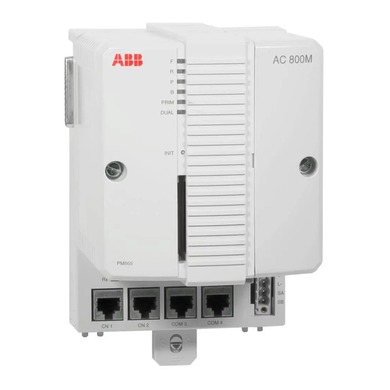
- Page 31 Processor unit interface unit Figure 1. Example of an AC 800M Controller (except PM891) with an S800 I/O Unit Figure 2 shows the PM861 processor unit that is part of the AC 800M controller. This processor unit is different from PM891.
- Page 32 AC 800M – General Section 1 Introduction Compact Flash slot Status Indicators INIT Push button CF Connector Tx/Rx RCU Link Optical ModuleBus Connector (PM861/PM864/ Electrical PM865/PM866) ModuleBus CEX-Bus Tx/Rx External Battery Status Supply Socket Indicators Power Supply Supervision Signal Socket...
-
Page 33: Pm8Xx/Tp830 Processor Unit - General
Section 1 Introduction PM8xx/TP830 Processor Unit – General PM8xx/TP830 Processor Unit – General The topic does not apply to PM891. See PM891 Processor Unit – General page 40. Physically the PM8xx/TP830 Processor Unit consists of two basic parts: • Processor Unit (PM851/PM851A/PM856/PM856A/PM860/PM860A/PM861/PM861A/... - Page 34 PM8xx/TP830 Processor Unit – General Section 1 Introduction Processor Unit Cover Release Screw Cover Assembly CEX-Bus Electrical ModuleBus Fuses CEX-Bus/ModuleBus Baseplate TP830 Figure 3. Processor Unit Assembly – General View (here shown with PM860/TP830) 3BSE036351-510 A...
- Page 35 Section 1 Introduction PM8xx/TP830 Processor Unit – General +5V DC Power ModuleBus System and CEX-bus +3.3V DC user mem. controller controller Battery Compact Flash External battery (+3.3V) Communication INIT controllers Logic Ethernet Ethernet RS232 RS232 COM3 COM4 Figure 4. PM851/PM856/PM860 – Functional Block Diagram PM851/PM851A is restricted to one Ethernet (CN1) port.
- Page 36 PM8xx/TP830 Processor Unit – General Section 1 Introduction System Shadow CEX-Bus ModuleBus Interface and user memory mem. FPGA +24V +5V DC +3.3V Battery RCU Link (+3.3V DC) Compact Flash Communication Controllers INIT Logic Ethernet Ethernet RS232 RS232 RS232 COM3 COM4 COM4 PRIM DUAL Figure 5.
- Page 37 ModuleBus of an AC 800M Controller. However, a further seven clusters (each comprising up to 12 units) can be added to the optical ModuleBus, thus achieving a total count of 96 units per AC 800M Controller when using only the ModuleBus.
- Page 38 Unit Note 2 - Remote S800 I/O. Maximum 24 modules/station (12/cluster), 24 x 32 =768 modules per segment. Note 3 - Maximum one CEX-module for PM851. Figure 6. Example of AC 800M/S800 I/O Interconnection in Single CPU Configuration 3BSE036351-510 A...
- Page 39 Note 2 – Central S800 I/O. Max. 96 units. Note 3 – For example FOUNDATION Fieldbus Linking Device LD 800HSE Note 4 – Maximum one CEX-module for PM851. Figure 7. Example of AC 800M/S800 I/O and FOUNDATION Fieldbus High Speed Ethernet Interconnection in Single CPU Configuration 3BSE036351-510 A...
-
Page 40: Pm891 Processor Unit - General
PM891 Processor Unit – General Section 1 Introduction PM891 Processor Unit – General PM891 is a high performance controller, which is capable of handling applications with high requirements. PM891 connects to the S800 I/O system through the optical Modulebus. It can act as a stand-alone Process Controller, or as a controller performing local control tasks in a control network. - Page 41 Section 1 Introduction PM891 Processor Unit – General Figure 8 shows the front view, Figure 9 shows the top view, and Figure 10 shows the bottom view of PM891. LED Status Indicators CEX Bus Port External Battery Supply Socket Power supply Supervision Signal Socket...
- Page 42 PM891 Processor Unit – General Section 1 Introduction Screw terminals are provided for connections to the power supply and the external battery. The 24 V DC power supply powers all the units on the CEX-Bus. The optical module clusters are powered independently. RCU Data Link RCU Control Link INIT...
- Page 43 Section 1 Introduction PM891 Processor Unit – General Figure 10. PM891 - Bottom view with Tx1/Rx1 and CN1/CN2 ports. The Redundancy Link consists of two cables; RCU Data Link Cable and RCU Control Link Cable (see Figure Figure 11 shows the block diagram of PM891. 3BSE036351-510 A...
- Page 44 PM891 Processor Unit – General Section 1 Introduction Figure 11. Block diagram of PM891 3BSE036351-510 A...
- Page 45 (1 cluster only for PM851)Restrictions apply, see I/O documentation. Repeater Unit Note 2 - Remote S800 I/O. Maximum 24 modules/station (12/cluster), 24 x 32 =768 modules per segment. Note 3 - Maximum one CEX-module for PM851. Figure 12. AC 800M/S800 I/O Interconnection Configuration with single PM891 3BSE036351-510 A...
- Page 46 Note 2 – Central S800 I/O. Max. 96 units. Note 3 – For example FOUNDATION Fieldbus Linking Device LD 800HSE Figure 13. Example of AC 800M/S800 I/O and FOUNDATION Fieldbus High Speed Ethernet Interconnection in Single PM891 Configuration 3BSE036351-510 A...
-
Page 47: Pm891/Pm86X/Tp830 Processor Unit - Redundancy
Section 1 Introduction PM891/PM86x/TP830 Processor Unit – Redundancy PM891/PM86x/TP830 Processor Unit – Redundancy Processor unit redundancy is available for PM861, PM864, PM865, PM866, and PM891. In this case, the controller contains two processor units, each including memory for system and application software. One unit is acting as primary, the other is backup (hot stand-by). - Page 48 PM891/PM86x/TP830 Processor Unit – Redundancy Section 1 Introduction PM891 Redundancy The Redundancy Link in PM891 consists of two physical links. These are the RCU Data Link and the RCU Control Link. The RCU Data Link is a fast communication channel used to transfer the data required to keep the backup CPU synchronized with the primary CPU.
- Page 49 Section 1 Introduction PM891/PM86x/TP830 Processor Unit – Redundancy If the primary unit fails because of an error, the backup unit resumes execution from the last rollback point, which means the last execution unit is partially re-executed by the backup unit. In order to re-execute a portion of the execution unit without affecting the peripheral units (communication units on the CEX-Bus), the peripheral units' references are also logged between rollback points.
-
Page 50: Ac 800M High Integrity
AC 800M High Integrity AC 800M can easily be configured for usage in safety critical applications. The main components of such a system are PM865, SM810/SM811, SS823 and the S800 I/O High Integrity, running a High Integrity version of Control Software. The PM865 processor unit has increased internal diagnostics, compared to PM864. -
Page 51: Control Software
S800 I/O High Integrity module. Control Software The software used by the AC 800M Controller is named Control Software. This name does not stand for a specific software package; is merely a generic name for the scope of functions used in a controller. -
Page 52: Ethernet Address For Pm8Xx (Except Pm891)
Ethernet Address for PM8xx (Except PM891) Section 1 Introduction Ethernet Address for PM8xx (Except PM891) Each TP830 Baseplate is provided with a unique Ethernet address that provides every CPU with a hardware identity. This functionality takes the form of two identification addresses residing in the non-volatile memory of the TP830 Baseplate. - Page 53 Section 1 Introduction Ethernet Address for PM8xx (Except PM891) Figure 14. Identification Labels and their position on PM8xx (except PM891) 3BSE036351-510 A...
-
Page 54: Ethernet Address For Pm891
Ethernet Address for PM891 Section 1 Introduction Ethernet Address for PM891 Each PM891 unit is provided with a unique Ethernet address that provides hardware identity to the unit. This functionality takes the form of two identification addresses residing in the non-volatile memory of PM891. - Page 55 Section 1 Introduction Ethernet Address for PM891 Figure 15. Identification Labels and their position on PM891 3BSE036351-510 A...
-
Page 56: Ac 800M Controller - Key Features
• Allows connecting custom protocols of a large amount of Serial communication RS-232C ports. • Connection to MasterBus 300 Networks. • Connection to INSUM via Gateway (Ethernet/LON). • Connection to ABB Drives is available, over DriveBus and ModuleBus. 3BSE036351-510 A... -
Page 57: Product Release History
This number is required to keep the configuration of all units and components on the AC 800M platform together, and to act as a reference in the future between different documents. As the AC 800M hardware platform configuration grows in future releases, so the version number will increase accordingly. - Page 58 Product Release History Section 1 Introduction Table 2. AC 800M Release History Version Description User Doc New information about SS823 is 3BSE036351R4101 added. SM810 and Compact Flash have been added. CI862 is added. 3BSE036351R4001 PM851 is added 3BSE 036 351 R101...
-
Page 59: Section 2 Installation
The AC 800M system is designed for use within demanding industrial environments. This section provides information on standard requirements regarding the location at which or the building(s) in which the AC 800M Controller system is to be stored or installed. - Page 60 – Should the AC 800M system be installed in a control room, adjacent to large machinery such as shakers or large presses where frequent major vibration is expected, then shock absorbers or an isolation pad may be required to protect system equipment.
- Page 61 For additional information regarding design considerations, see Appendix B, Power Consumption. Electro-Magnetic Compatibility The AC 800M units are intrinsically EMC compatible according to CE marking rules. For additional information regarding Electro-Magnetic Compatibility, Appendix D, Directive Considerations. 3BSE036351-510 A...
-
Page 62: Cables
10 cm (4 in) from other cables. • All cables connected to AC 800M should be routed at a distance of 30cm (12 in) from all power cables and 10 cm (4 in) from cables belonging to the relevant international immunity standard, class 4. -
Page 63: Power Supply
Section 2 Installation Power Supply Power Supply Under normal circumstances, the power supply required by AC 800M Controller and associated field equipment can be obtained from the plant’s standard 120/230 V AC mains supply. Mains Net Filter It is not necessary to use mains net filters when using the SD831/832/833/834 power supply units. -
Page 64: Enclosures
Uninterruptable Power Supply (UPS) device. The AC 800M controller will shut down safely in the event of a power failure. During down-time, the application memory and the system clock will be backed up by the internal battery. -
Page 65: Mounting Ac 800M Units Onto Din-Rail
If the enclosure is provided with removable wall cladding, it is important to ensure that this is not removed from any enclosure adjacent to other enclosures containing equipment not belonging to the AC 800M Controller and its connected S800 I/O. ABB Cabinets As a suitable enclosure, ABB recommends the following two cabinets, both specially adapted for mounting the AC 800M Controller and S800 I/O. -
Page 66: Mounting On Metal Sheet
EMI immunity and RF emission of the modules. The DIN mounting rail must have a good bond to the PE of the cabinet. If AC 800M modules are configured as two or more groups interconnected with extension cables, special care should be taken to ensure that the DIN-rails of all groups have a good connection to ground. -
Page 67: Prefabricated Aluminum Profile
The profile has grooves for screws that can be used for fastening the modules in an environment with high vibrations. The AC 800M Controller and associated units must be unpowered and disconnected when being mounted onto a DIN-rail! 3BSE036351-510 A... - Page 68 DIN-rail. It is essential that the locking device be placed in the LOCKED position to avoid possible problems caused by vibration and/or intermittent grounding. For further visual information on mounting AC 800M Controller units, Figure 18 on page 69.
- Page 69 Section 2 Installation Prefabricated aluminum profile 1. OPEN 2. SLIDE 3. LOCKED Figure 17. Baseplate Locking Device Lugs for extra screws to provide secure mounting in locations subject to vibration Figure 18. DIN-rail Mounting of AC 800M Units 3BSE036351-510 A...
- Page 70 Prefabricated aluminum profile Section 2 Installation Figure 19. AC 800M Controller (except PM891) – Side View Mounting Procedure for PM891 Unit Before mounting any processor unit or communication interface on the DIN-rail, read carefully the installation instructions provided with the equipment.
- Page 71 Section 2 Installation Prefabricated aluminum profile When the interconnection is complete, rotate the locking device clockwise to the LOCKED position (3). The PM891 unit is now fully locked into the position and has a good ground connection to the DIN-rail. It is essential that the locking device be placed in the LOCKED position to avoid possible problems caused by vibration and/or intermittent grounding.
- Page 72 Figure 22. PM891 - Side view Removing Processor Units Complete with Baseplates AC 800M units must be disconnected from the power source before removing them from a DIN-rail! It is not allowed to manipulate CEX bus baseplates in a powered and running system.
- Page 73 Turn the locking device anti-clockwise to the OPEN position (1) and ease the unit baseplate outward and upward at the base. Lift the unit to remove it from the DIN-rail. The AC 800M units must be disconnected from the power source before removing them from the DIN-rail.
- Page 74 Prefabricated aluminum profile Section 2 Installation Rx/Tx INIT PM860 CI853 CI851 COM1 COM2 CN2 COM3 COM4 Figure 23. Separating the Baseplates 3BSE036351-510 A...
- Page 75 Section 2 Installation Prefabricated aluminum profile Unit to Baseplate Alpha Code Lock Baseplates have a pre-set Alpha code locking device. This locking device prevents the installation of an incompatible type of unit onto the base plate if the Alpha codes do not match.
- Page 76 The mechanical keys are delivered pre-set and must not be altered. This prevents the removable interface being placed on the wrong type of baseplate. Do not manipulate the locking device. ABB will take no responsibility for errors caused by manipulating locking devices.
- Page 77 Section 2 Installation Prefabricated aluminum profile Pre-Set Alpha Code Keys Figure 24. Unit Baseplate – Alpha Code Lock Arrangement 3BSE036351-510 A...
-
Page 78: Installing The Pm86X/Tp830 Processor Unit In Single Configuration
Installing the PM86x/TP830 Processor Unit in Single Configuration Section 2 Installation Installing the PM86x/TP830 Processor Unit in Single Configuration This topic does not apply to the PM891 processor unit. See Installing PM891 in Single Configuration on page 87. Use the procedure below to install the processor unit along the DIN-rail: If already mounted, remove the CEX-Bus and ModuleBus terminations from the sides of the processor unit. - Page 79 144. Do not place the internal back-up battery in the battery holder until the AC 800M Controller has been powered-up normally and the memory back-up function has been activated, that is, the B(attery) LED flashes. If no normal power supply is connected to the processor unit with the battery in place, then the CPU memory will immediately start to consume battery power.
- Page 80 Installing the PM86x/TP830 Processor Unit in Single Configuration Section 2 Installation Always install a fresh internal or external battery at the end of the installation phase. The original battery is heavily utilized due to frequent blackouts during system installation. ...
- Page 81 Section 2 Installation Installing the PM86x/TP830 Processor Unit in Single Configuration TK850 Cable Terminator TB851 Figure 26. TB851 Terminator for CEX-Bus (female) 3BSE036351-510 A...
- Page 82 Installing the PM86x/TP830 Processor Unit in Single Configuration Section 2 Installation BC810 PM861A/PM864A/PM865 Terminator TB850 RCU Link Terminator Cable TB850 BC810 Figure 27. CEX-Bus Terminator when using BC810 3BSE036351-510 A...
- Page 83 Section 2 Installation Installing the PM86x/TP830 Processor Unit in Single Configuration Figure 28. SA/SB Connectors for Supervision Signals 3BSE036351-510 A...
- Page 84 Use an RJ45 connector for IEEE802.3 (Ethernet) for connecting to a category 5 Shielded Twisted Pair cable (STP class 5). Class 5, or higher, cable 10/100BaseT/TX max 100 m (110 yd). ABB recommends the use of optical fiber in an industrial environment, for example 62.5/125 100BaseFX, max.
- Page 85 Section 2 Installation Installing the PM86x/TP830 Processor Unit in Single Configuration COM3 Port The COM3 is an RS-232C port with modem signals. This port is used for serial protocols such as Modbus, Siemens 3964R, COMLI or custom-design. Table 6. TP830 COM3 Connections (RJ45 connector) Designation Direction Description...
- Page 86 Installing the PM86x/TP830 Processor Unit in Single Configuration Section 2 Installation COM4 Port The COM4 port is an RS-232C port, opto-isolated and without modem signals. Connect Control Builder to this port when connecting directly to the controller, or, when not required, without the need use the remote tool connection via the Control Network.
-
Page 87: Installing Pm891 In Single Configuration
Section 2 Installation Installing PM891 in Single Configuration Installing PM891 in Single Configuration Use the procedure below to install the PM891 processor unit in single configuration: If already connected, remove the CEX-Bus termination from the side of the PM891 processor unit. Mount the PM891 processor unit, the communication interfaces, and the S800 I/O units on the DIN-rail.... - Page 88 Use an RJ45 connector for IEEE802.3 (Ethernet) for connecting to a category 5 Shielded Twisted Pair cable (STP class 5). Class 5, or higher, cable 10/100BaseT/TX max 100 m (110 yd). ABB recommends the use of optical fiber in an industrial environment, for example 62.5/125 100BaseFX, max.
- Page 89 Section 2 Installation Installing PM891 in Single Configuration COM4 Port The COM4 port is an RS-232C port, opto-isolated and without modem signals. Connect the Control Builder to this port when connecting directly to the controller, or, when not required, without the need use the remote tool connection through the Control Network.
-
Page 90: Installing The Pm86X/Tp830 Processor Unit In Redundant Configuration
Installing the PM86x/TP830 Processor Unit in Redundant Configuration Section 2 Installation Installing the PM86x/TP830 Processor Unit in Redundant Configuration This topic does not apply to the installation of PM891 unit in redundant configuration. See Installing the PM891 Processor Unit in Redundant Configuration on page 94. - Page 91 Section 2 Installation Installing the PM86x/TP830 Processor Unit in Redundant Configuration Connect the RCU Link Cable TK851 to both CPUs. Note that in redundant CPU configuration, COM3 and the electrical ModuleBus on the baseplate can not be used. Note that the RCU Link Cable TK851 must be used and can not be replaced by a similar cable.
- Page 92 144. Do not place the internal back-up battery in the battery holder until the AC 800M Controller has been powered-up normally and the memory back-up function has been activated, that is, the B(attery) LED flashes. If no normal power supply is connected to the processor unit with the battery in place, then the CPU memory will immediately start to consume battery power.
- Page 93 Section 2 Installation Installing the PM86x/TP830 Processor Unit in Redundant Configuration Communication Ports Same as for single configuration (see Table 5 on page 84, Table 6 on page 85 and Table 7 on page 86). CEX-Bus ext. cable TK850 RCU Link cable TK851 Figure 29.
-
Page 94: Installing The Pm891 Processor Unit In Redundant Configuration
Installing the PM891 Processor Unit in Redundant Configuration Section 2 Installation Installing the PM891 Processor Unit in Redundant Configuration In redundant configuration, two PM891 units are mounted on two separate DIN-rails. If sufficient space is available, the units can be mounted on the same DIN-rail. - Page 95 Section 2 Installation Installing the PM891 Processor Unit in Redundant Configuration Provide connections for power supply and network: Connect the power leads to screw terminals L+ and L- of both CPUs, and the power supervision signals from SS8xx to screw terminals SA and SB. Both CPUs should be powered from the same supply (single or redundant).
- Page 96 Installing the PM891 Processor Unit in Redundant Configuration Section 2 Installation Figure 30. Example of PM891-Redundant configuration Communication Ports Same as for single configuration (see Table 8 on page 88and Table 9 on page 89). 3BSE036351-510 A...
-
Page 97: Installing The Cex-Bus Without Bc810
Section 2 Installation Installing the CEX-Bus without BC810 Installing the CEX-Bus without BC810 The CEX-Bus, used for connection of communication interfaces to the processor unit, is located on the left-hand side of the processor unit baseplate (TP830). A bus termination unit must always be fitted to the last unit on the CEX-Bus, as shown in Figure 25 on page 80. - Page 98 136. See also Powering from an External Source on page 176. In AC 800M High Integrity Controllers it is required that the external supply input of BC810 is connected and that the power supply is strictly configured either according to Figure 33...
- Page 99 “direct BC810”, might jeopardize the whole controller and should not be performed unless every module on the CEX-Bus are in a non- operating state. Note: In an AC 800M HI controller this is unconditionally and intentionally leading to a shutdown of the controller.
- Page 100 Installing the CEX-Bus Interconnection Unit BC810/TP857 Section 2 Installation BC810 PM861A/PM864A/PM865/PM866 SM810/SM811 TK851 Cables PM861A/PM864A/PM865/PM866 SM810/SM811 BC810 (1) Only for High Integrity Systems and only together with PM865 Figure 31. Redundant Communication Interface Units and Controllers 3BSE036351-510 A...
- Page 101 Section 2 Installation Installing the CEX-Bus Interconnection Unit BC810/TP857 CI854A SM810/SM811 BC810 PM861A/PM864A/PM865/PM866 RCU Link Cable CI854A SM810 BC810 (1) Only for High Integrity Systems and only together with PM865 Figure 32. Redundant Communication Interface Units and Single Controller 3BSE036351-510 A...
- Page 102 Installing the CEX-Bus Interconnection Unit BC810/TP857 Section 2 Installation CEX-Bus Units BC810 SD8xx/SS8xx CEX-Bus Units BC810 Figure 33. The Power Source Connected to the Same PM864/BC810 Segment, see Installing the CEX-Bus Interconnection Unit BC810/TP857 on page 97 and Power Supply System on page 173.
- Page 103 Section 2 Installation Installing the CEX-Bus Interconnection Unit BC810/TP857 CEX-Bus Units BC810 SM810/SM811 SD8xx/SS8xx SD8xx/SS8xx SM810/ CEX-Bus Units SM811 BC810 Figure 34. The Power Source Connected to a Different PM865/BC810 Segment, see Installing the CEX-Bus Interconnection Unit BC810/TP857 on page 97 and Power Supply System on page 173.
-
Page 104: Installing Sm810/Tp855
SM810’s. The input signals are used for system function, see AC 800M High Integrity documentation. Table 10. SM810 Digital I/O Connector... - Page 105 Section 2 Installation Installing SM810/TP855 Connection of Input Signals to SM810 0V B 0V A I1: Reset all forces I2: Access enable 24V A 24V B Figure 35. Connection of input signals to redundant SM810. 3BSE036351-510 A...
- Page 106 Installing SM810/TP855 Section 2 Installation Connection of Output Signals to SM810 24V B 24V A O1: Any force active O2: System alarm Figure 36. Connection of output signals from redundant SM810. 3BSE036351-510 A...
-
Page 107: Installing Sm811/Tp868
SM811’s. The input signals are used for system function, see AC 800M High Integrity documentation. Table 11. SM811 Digital I/O Connector... - Page 108 Installing SM811/TP868 Section 2 Installation Table 11. SM811 Digital I/O Connector Designation Description Digital output 2 (System alarm) Common I/O return 3BSE036351-510 A...
- Page 109 Section 2 Installation Installing SM811/TP868 Connection of Input Signals to SM811 0V B 0V A I1: Reset all forces I2: Access enable I3: Hot-insert of SM 24V A 24V B Figure 37. Connection of input signals to redundant SM811 3BSE036351-510 A...
- Page 110 Installing SM811/TP868 Section 2 Installation Connection of Output Signals to SM811 24V B 24V A O1: Any force active O2: System alarm Figure 38. Connection of output signals from redundant SM811 3BSE036351-510 A...
-
Page 111: Installing The Profibus Dp Interface, Ci851/Tp851
The CI851 is powered from the processor unit via the CEX-Bus and requires therefore no additional external power source. Use the following procedure to install the CI851/TP851: Mount the unit onto the DIN-rail, see Mounting AC 800M Units onto DIN-Rail on page 65 and Installing the PM86x/TP830 Processor Unit in Single Configuration on page 78. - Page 112 Installing the PROFIBUS DP Interface, CI851/TP851 Section 2 Installation Installation of PROFIBUS DP Table 12. CI851 - PROFIBUS DP Connector Designation Description Shield Shield/protective ground – Not Used B-line Receive/Transmit Data B-line RTS(TTL) Indicates direction RTS(TTL) Indicates direction GND Bus GND Bus +5 V Bus For terminating resistors...
-
Page 113: Installing The Foundation Fieldbus H1 Interface, Ci852/Tp852
No field device on the FF H1 bus is powered from the CI852. An AC 800M Controller connected to a CI852 constitutes a FOUNDATION Fieldbus linking device. Use the following procedure to install the CI852/TP852:... - Page 114 Installing the FOUNDATION Fieldbus H1 Interface, CI852/TP852 Section 2 Installation For additional information on designing a fieldbus (connectors, cables and devices), see fieldbus documentation. A catalog referencing suppliers, devices, services and other fieldbus-related items, is available for FIELDBUS ONLINE via the Internet web site. Powering Field Devices Field devices requiring power from the fieldbus need special power supplies connected to the data wires (in the same way as a field device).
-
Page 115: Installing The Rs-232C Interface, Ci853/Tp853
CI853 is powered from the processor unit via the CEX bus and requires therefore no additional external power source. Use the following procedure to install the CI853/TP853: Mount the unit onto the DIN-rail, see Mounting AC 800M Units onto DIN-Rail on page 65 and Installing the PM86x/TP830 Processor Unit in Single Configuration on page 78. -
Page 116: Installing The Profibus Dp Interface, Ci854/Ci854A/Tp854
Use the following procedure to install the CI854/CI854A/TP854: Mount the unit onto the DIN-rail, see Mounting AC 800M Units onto DIN-Rail on page 65 and Installing the PM86x/TP830 Processor Unit in Single Configuration on page 78. - Page 117 Section 2 Installation Installing the PROFIBUS DP Interface, CI854/CI854A/TP854 PRIM PRIM DUAL DUAL CI854A CI854A Line A Line B Figure 39. Connection of Redundant PROFIBUS DP (CI854A) PROFIBUS DP Connection The PROFIBUS DP cable is connected via the 9-pin female D-type connector located on TP854.
- Page 118 Installing the PROFIBUS DP Interface, CI854/CI854A/TP854 Section 2 Installation Installation of PROFIBUS DP Table 15. CI854/CI854A – PROFIBUS DP Connector Designation Description Shield Shield/protective ground – Not Used RxD/TxD-P Receive/Transmit Data P-line (B-line) CNTR-P Indicates Direction to Repeater (TTL) DGND Digital Ground +5 V, for terminating resistors –...
-
Page 119: Installing The Masterbus 300 Interface, Ci855/Tp853
The baseplate, TP853, provides two Ethernet ports for connection of redundant Ethernet network for MasterBus 300. Use the following procedure to install the CI855/TP853: Mount the unit on the DIN-rail, see Mounting AC 800M Units onto DIN-Rail on page 65 and Installing the PM86x/TP830 Processor Unit in Single Configuration on page 78. -
Page 120: Installing The S100 I/O Interface, Ci856/Tp856
The CI856 is powered from the processor unit via the CEX-Bus and requires therefore no additional external power source. Use the following procedure to install the CI856/TP856: Mount the unit on the DIN-rail, see Mounting AC 800M Units onto DIN-Rail on page 65 and Installing the PM86x/TP830 Processor Unit in Single Configuration on page 78. -
Page 121: Installing The Insum Interface, Ci857/Tp853
The CI857 is powered from the processor unit via the CEX-Bus and requires therefore no additional external power source. Use the following procedure to install the CI857/TP853: Mount the unit onto the DIN-rail, see Mounting AC 800M Units onto DIN-Rail on page 65 and Installing the PM86x/TP830 Processor Unit in Single Configuration on page 78. -
Page 122: Installing The Drivebus Interface, Ci858/Tp858
The unit is mounted onto a horizontal DIN rail. Mount the unit onto the DIN-rail, see Mounting AC 800M Units onto DIN-Rail page 65, Installing the PM86x/TP830 Processor Unit in Single Configuration page 78 and CI858 and TP858 –... -
Page 123: Installing The Foundation Fieldbus High Speed Ethernet Interface, Ci860/Tp860123
The CI860 is powered from the processor unit via the CEX-Bus and requires therefore no additional external power source. Use the following procedure to install the CI860/TP860: Mount the unit onto the DIN-rail, see Mounting AC 800M Units onto DIN-Rail on page 65 and Installing the PM86x/TP830 Processor Unit in Single Configuration on page 78. -
Page 124: Installing The Trio Fieldbus Interface Ci862
Installing the TRIO Fieldbus Interface CI862 Section 2 Installation Installing the TRIO Fieldbus Interface CI862 The CI862 is powered from the processor unit via the CEX-Bus and requires no additional external power source. No field device is powered from the CI862. Use the following procedure to install the CI862: Mount the unit onto the DIN-rail. - Page 125 Section 2 Installation Bus Termination Table 17. Field Bus Termination Switch Settings of the CI862 (Continued) Dip Switch Setting 150 ohms Not Used (1) The dip switch must be closed to make the termination connection. The default is open, (no internal termination). (2) The 110 ohm option may be used to terminate cables with an impedance in the range of 100 to 120 ohms.
-
Page 126: Installing The Satt I/O Units And Ci865 Module
No field device is powered from the CI865. Use the following procedure to connect the ControlNet to the BNC connector of the I/O systems and the CI865 module. For more information see Satt I/O Interface for AC 800M (3BSE042821*). The BNC connector is located: •... -
Page 127: Installing The Modbus Tcp Interface Ci867/Tp867
Use the following procedure to install the CI867/TP867: Mount the unit onto the DIN-rail, see Mounting AC 800M Units onto DIN- Railon page 65 and Installing the PM86x/TP830 Processor Unit in Single Configurationon page 78. -
Page 128: Installing The Iec 61850 Interface Ci868
The CI868 is powered from the processor unit via the CEX-Bus with no additional external power source required. To install CI868: Mount the unit onto the DIN-rail, see Mounting AC 800M Units onto DIN- Railon page 65. Connect the 100Mbps Ethernet twisted pair cable to the CH1 connector on the baseplate. -
Page 129: Installing The Profinet Io Interface Ci871
CI872. Leave the protective plugs mounted on unused ports. Connect the other end of the fiber optic cable to a MOD5 controller. Fiber Optics Specifications The following data applies for the fiber optics connections between the AC 800M controller and MOD5 controllers: •... -
Page 130: Installing The Ethernet/Ip Interface Ci873
Installing the EtherNet/IP Interface CI873 Section 2 Installation Installing the EtherNet/IP Interface CI873 The CI873 is powered from the processor unit through the CEX-Bus, which requires no additional external power source. Follow the steps below to install CI873: Mount the unit onto the DIN-rail. Connect the 100 Mbps Ethernet twisted pair cable to the CH1 connector on the baseplate. -
Page 131: Installing The Modulebus For Pm8Xx
Section 2 Installation Installing the ModuleBus for PM8xx Installing the ModuleBus for PM8xx This topic does not apply to PM891. See Installing the ModuleBus for PM891 page 132. The ModuleBus has an electrical and a fiber optical interface that are logically the same buses. -
Page 132: Installing The Modulebus For Pm891
Installing the ModuleBus for PM891 Section 2 Installation Installing the ModuleBus for PM891 The ModuleBus for PM891 has a fiber optical interface. The interface is designed for a maximum of seven clusters, of twelve non-redundant or six redundant modules (that is, 7x12 = 84 modules). Redundant and non-redundant modules can be mixed. The fiber-optical interface is intended for local distribution of I/O clusters. -
Page 133: Installing The Sd83X Power Supply
Section 2 Installation Installing the SD83x Power Supply Installing the SD83x Power Supply The SD83x power supply units (SD831 / SD832 / SD833 / SD834) should be mounted horizontally at a DIN rail. The units have to be used in non-hazardous locations only. -
Page 134: Installing The Mains Breaker Unit
Installing the Mains Breaker Unit Section 2 Installation Installing the Mains Breaker Unit The mains breaker unit is supplied in separate components that must be mounted onto a DIN-rail in order to form a complete assembly. Different distribution options are available, see Figure 61 on page 177 and Figure 62... - Page 135 Section 2 Installation Installing the Mains Breaker Unit Removing the fuse holders or the jumper connections provides visual indication if the power supply has been disconnected. The fuse holders have built-in red LEDs to indicate a ruptured (defective) fuse. PE – Green/Yellow To Power PE –...
-
Page 136: Installing The Ss823/Ss832 Voting Unit
Installing the SS823/SS832 Voting Unit Section 2 Installation Installing the SS823/SS832 Voting Unit The SS8xx voting unit is used to connect two redundant power supplies to a common load. Depending on the system configuration requirements, the two redundant power supplies may be connected to completely separate mains supplies or to the same mains supply, as shown in Figure 43 on page 137 for SS823,... - Page 137 Section 2 Installation Installing the SS823/SS832 Voting Unit Figure 43. Redundant Power Supply for SS823 3BSE036351-510 A...
- Page 138 Installing the SS823/SS832 Voting Unit Section 2 Installation Figure 44. SS832 Redundant Configuration up to 10 A 3BSE036351-510 A...
- Page 139 Section 2 Installation Installing the SS823/SS832 Voting Unit Figure 45. SS832 Redundant Configuration up to 20 A Connect the SS82x voting unit to the processor unit. Figure 46 on page 140 shows the connection to PM861/PM864/PM865 in redundant configuration. 3BSE036351-510 A...
- Page 140 Installing the SS823/SS832 Voting Unit Section 2 Installation From Mains Breaker Protective Ground Figure 46. Redundant Power Supply Powering Redundant CPUs 3BSE036351-510 A...
- Page 141 Here the SA/SB signals also indicate physical power supplies. Figure 48 on page 142 shows one redundant power supply powering the AC 800M units and one for powering field equipment. An SA/SB error indication can not indicate which physical power supply that has failed, only that there is a failure.
- Page 142 Installing the SS823/SS832 Voting Unit Section 2 Installation Supervision signals to CPU unit via TP830 L+ L+ L– L– L+ L+ L– L– F OK SS822 SD821 SD821 L PE L PE A+ B+ L+ L+ L– +24 V From Mains Powering Breaker Units...
-
Page 143: Installing The Sb821 External Battery Unit
PM8xx in order to avoid reducing available memory back-up time. Do not connect the TK821V020 cable until the AC 800M Controller has been powered-up normally and the memory back-up function has been activated, that is, the B(attery) LED flashes. -
Page 144: Installing The Sb822 Rechargeable External Battery Unit
Connect the 24V supply to the connector enclosed in the packing box. Connect the 24V supply to the battery unit (X3) Make sure that the AC 800M controller is powered and that the battery LED in the front of PM8xx is flashing Connect the SB822 rechargeable external battery unit, use the 2 m (2.2 yd) -
Page 145: Installation Of I/O Units
I/O Units, refer to the appropriate I/O system documentation. Installation in Cabinets The figures listed below are examples of how the AC 800M Controllers, Power Supply units, Voting units and S800 I/O units can be configured and mounted within cabinets: •... - Page 146 Installation in Cabinets Section 2 Installation ModuleBus Expansion Cable Aluminum Profile Cable Duct Mains Breaker SD831 24 V Distribution Unit Terminals Figure 49. Wall Cabinet – Single Power Supply Arrangement 3BSE036351-510 A...
- Page 147 Section 2 Installation Installation in Cabinets Mains Breaker SD831 SD831 Unit (Units) (Field) 24 V Distribution 24 V Distribution (Units in Cabinet) (Field Equipment) Figure 50. Wall Cabinet – Dual Power Supply (Local/Field) Arrangement 3BSE036351-510 A...
- Page 148 Installation in Cabinets Section 2 Installation SD832 Redundant Power Supply Units (Field Equipment) Mains Breakers SS832 Voting Units SD832 Redundant Power Supply Units Figure 51. Floor Mounted Cabinet (Horizontal Unit Arrangement) 3BSE036351-510 A...
-
Page 149: Mounting Dimensions For Proper Ventilation
Mounting Dimensions for Proper Ventilation Mounting Dimensions for Proper Ventilation To maintain adequate cooling airflow through the AC 800M Controller units, there must be no obstruction within 50 mm (2 in) above and 25 mm (1 in) below the units,... - Page 150 Mounting Dimensions for Proper Ventilation Section 2 Installation 3BSE036351-510 A...
-
Page 151: Section 3 Configuration
• Control Builder documentation – for configuration information • Control Software documentation – for available functionality. Control Builder Online Help provides detailed step-by-step information when creating an application for the AC 800M Controller. 3BSE036351-510 A... -
Page 152: Connecting Control Builder
Alternatively, the Control Builder may be connected via the COM4 port (RS-232C) on the AC 800M Controller. Use the tool cable TK212 and a serial port on the PC. In redundant configuration, the Control Builder is connected to the Primary CPU COM4 port. -
Page 153: Connection To A Control Network
INDUSTRIAL ENVIRONMENT NON-INDUSTRIAL ENVIRONMENT Switch FO = Fiber Optic link STP = Shielded Twisted Pair Link USE STP GENERALLY Control Builder Operator Station Figure 53. Example of AC 800M Controllers Connected to a Control Network 3BSE036351-510 A... -
Page 154: Communication Possibilities
Ethernet and PPP. It provides for full redundancy, in order to achieve high network availability. The AC 800M controller is always connected to the Control Network via an STP (Shielded Twisted Pair) cable. Should the local environment be of an industrial nature, the AC 800M / Control Network connection must be converted over to a Fiber Optic (FO) cable. - Page 155 Section 3 Configuration Communication Possibilities • COM3 is an RJ45 port for RS-232C with modem signals. Examples of protocols are Modbus, Siemens 3964R, COMLI or custom-design. For more details, see protocol-specific documentation. COM3 port is not available for PM891. • COM4 is an RJ45 port for connection of service tools (see Connecting Control Builder...
- Page 156 Communication Possibilities Section 3 Configuration Table 19. Interfaces Available on the CEX-Bus Number of Interfaces on CEX-Bus Number of Interface ports per Maximum of Maximum Interface each total on (1)(2) interface CEX-Bus CI851 (PROFIBUS DP) CI852 (FOUNDATION Fieldbus H1) CI853 (RS-232C) CI854/CI854A...
-
Page 157: Controller Ip Addresses
Section 3 Configuration Controller IP Addresses (2) The maximum total limit on CEX-Bus is the electrical one, there might be further limitations due to performance for a particular unit. (3) Only one port (CH1) is used in the interfaces CI868, CI871 and CI873. For information on available serial protocols for the CI853 interface, see COM3 above. -
Page 158: I/O Systems
CPU takes over, it also takes over the primary IP address that is defined in Control Builder. Other units on the control network will never notice the switchover. I/O Systems There are several methods of connecting I/O systems to the AC 800M Controller: • S100 I/O via CI856. •... - Page 159 S900 I/O units can be connected to PROFIBUS DP. • ABB Drives can be connected to the ModuleBus, via CI801 and also via Modulebus on the PM8xx. Some Drives equipment can be connected directly to PROFIBUS or PROFINET IO. Please refer to Drives-specific documentation for more information.
- Page 160 I/O Systems Section 3 Configuration This provides a total of eight clusters (groups), with a maximum 8 x 12 = 96 S800 I/O units connected to an AC 800M Controller with single CPU configuration. Optical Electrical ModuleBus ModuleBus PM8xx Local...
- Page 161 Section 3 Configuration I/O Systems In redundant CPU configuration, S800 I/O is connected through the optical ModuleBus. Each CPU is connected to one TB840 on each cluster (see Figure 55 page 161). Redundant CPUs Electrical ModuleBus cannot be used Local 2 x TB840 Central/Remote Optical...
- Page 162 I/O Systems Section 3 Configuration PROFIBUS DP A PROFIBUS DP segment, capable of providing up to 32 nodes, can be directly connected to a PROFIBUS DP Interface unit type CI854A/TP854. This segment can be further extended using repeater units. PROFIBUS PA can be connected to PROFIBUS DP via the PROFIBUS linking device LD 800P, see Appendix C, Recommended Components.
- Page 163 Section 3 Configuration I/O Systems Figure 56. Example of System Structure for PROFIBUS PROFINET IO PROFINET IO describes a device model oriented to the PROFIBUS framework. It consists of places of insertion (slots) and groups of I/O channels (subslots). The PROFINET IO engineering is performed in a way familiar to PROFIBUS.
- Page 164 I/O Systems Section 3 Configuration The PROFINET IO is interfaced to the AC 800M controller , using the PROFINET IO commmunication interface, CI871. Figure 57. PROFINET IO with AC 800M 3BSE036351-510 A...
- Page 165 H1 segments and devices on the HSE segment.The FOUNDATION Fieldbus HSE and H1network and the devices are configured with the Fieldbus Builder FOUNDATION Fieldbus. The FF subsystem is interfaced to the IEC 61131 controller (AC 800M) using a FF HSE unit CI860 in the AC 800M, see Figure 7 on page 39.
- Page 166 I/O Systems Section 3 Configuration FF linking devices operate as gateways between the AC 800M and the field devices on the H1segments both for the configuration data of the field devices and for the process data which is exchanged cyclically between AC 800M and the field devices.
- Page 167 TRIO/Genius Remote I/O TRIO is a Genius remote I/O product that provides discrete, analog and high-speed counter blocks for connection to the AC 800M. Configuration of the I/O block units and the CI862 is done using Control Builder M. 3BSE036351-510 A...
-
Page 168: Drive System
Drive System Section 3 Configuration Drive System ABB Standard (Std) and Engineered (Eng) Drives can be connected to AC 800M through any of the following: • The optical ModuleBus • CI801 and PROFIBUS DP • NPBA-12, RPBA-01, or FPBA-01 PROFIBUS DP Adaptor modules along with CI854 •... - Page 169 PROFINET IO network, and it is compatible with all PNIO controller stations that support PROFINET IO and sub-slots. DriveBus Interface CI858 ABB drives can be connected to the AC 800M via the CI858 unit, see Figure 59 page 171 and Figure 60 on page 172.
- Page 170 Drive System Section 3 Configuration • ACS 1000 product family See also CI858 and TP858 – DriveBus Interface on page 313 3BSE036351-510 A...
- Page 171 PROFIBUS DP CI801 Max 12 Modules per Cluster Optical Optical ABB Std Drive TB820 Branching ABB Std Drive ABB Std Unit Drive ABB Std Drive Optical Figure 59. Example of Connection of ABB Drives in Single CPU Configuration 3BSE036351-510 A...
- Page 172 Drive System Section 3 Configuration DRIVEBUS CI858 MSTR Branching MSTR . . . NDBU NDBU Units ..Drive Drive Drive Drive Drive Drive Up to 24 Drives Figure 60. DriveBus Topology 3BSE036351-510 A...
-
Page 173: Power Supply System
SS83X voting devices – to the 24 V DC distribution terminals. The AC 800M Controller and its I/O system are normally located in one or several enclosures or cabinets. The cabinet housing the AC 800M Controller can also contain I/O units connected to the controller via the electrical ModuleBus, the optical ModuleBus or the communication interfaces for PROFIBUS DP. -
Page 174: Powering Units In The Cabinet
Interference Powering field equipment from a power supply located in the AC 800M Controller cabinet often requires the use of long 24 V DC cables that can easily pick up local interference and direct it straight back to the power supply units. When installing the... - Page 175 Section 3 Configuration Powering Field Equipment outside the Cabinet To avoid the AC 800M Controller being influenced by field equipment, it is strongly recommended that separate power supplies be installed (see Figure 50 on page 147 Figure 51 on page 148).
-
Page 176: Powering From An External Source
Section 3 Configuration Powering from an External Source The AC 800M Controller can be powered from an external +24 V DC source. This source is often common for many different types of plant equipment, resulting in long power cables to the AC 800M Controller. Furthermore, heavy load changes can cause variations in controller supply voltage making it necessary to take precautions against low voltage in order to prevent controller malfunction. - Page 177 Voting Terminals Device Power Supplies Redundant Mains Power Supplies Mains 1 Supply to Units Mains Breaker 24 V DC Distribution Voting Mains 2 Device Terminals Mains Breaker Power Supplies Figure 61. Power Supply Options for AC 800M Units 3BSE036351-510 A...
- Page 178 Powering from an External Source Section 3 Configuration Powering Field Equipment Supply to Units Mains 24 V DC Mains Breaker Distribution Terminals Independent Power Supplies Supply to Field Equipment 24 V DC Distribution Terminals Supply to Units Mains 24 V DC Mains Breaker Distribution Independent...
-
Page 179: Section 4 Operation
Section 4 Operation This section describes the operation of the AC 800M Controller, comprising a PM8xx (single or redundant configuration) processor unit, together with various optional units. For additional technical information on optional units, see Appendix A, Hardware Units. AC 800M Controller (PM8xx) Equipped with Control Software, the basic PM8xx/TP830 or PM891 hardware units mounted on the AC 800M hardware platform constitute an AC 800M Controller. - Page 180 AC 800M Controller (PM8xx) Section 4 Operation Table 20. PM8xx – LED Indicators (Continued) Marking Color Function P(ower) Green Normal state – ON When lit, indicates that the CPU DC/DC converter is generating valid +5 V and +3.3 V DC supply voltages.
- Page 181 Section 4 Operation AC 800M Controller (PM8xx) Switches and Push buttons Table 21. PM8xx – Switches and Push buttons Marking Type Function INIT Manual Push Initiates button 1. Cold Restart if INIT is held less than 2.5 seconds. 2. Controller Reset if INIT is held more than 3 seconds.
-
Page 182: Start-Up
The redundant configuration using CEX bus and CEX modules is supported along with the processor modules PM861, PM864, PM865, PM866 and PM891. At start-up, some things regarding the CEX bus and CEX modules have to be considered when starting up a redundant AC 800M system: • Without using BC810 units: –... -
Page 183: Start Modes
Section 4 Operation Start Modes – After having rebuilt the hardware on the CEX bus, that is, after removing or adding a number of base plates (equipped with CEX modules or not) the upper CPU (the CPU connected to the part of the RCU Link cable that is marked “UPPER”) must be started as the primary CPU the first time. -
Page 184: Automatic Switch-Over To Backup Cpu
Automatic Switch-Over to Backup CPU Section 4 Operation Controller Reset The system stops. The application program and variables are erased. To initiate Controller Reset, press and hold the Controller INIT push button (more than three seconds) until the Run LED begins to flash. A Controller Reset must be performed if the system is in an undefined position and consequently unavailable to the user. -
Page 185: Verification Of Satisfactory Ac 800M Operation
Section 4 Operation Verification of Satisfactory AC 800M Operation Verification of Satisfactory AC 800M Operation To affirm, following start-up, that the AC 800M Controller and all associated units are operating correctly, see Table 23 on page 185. Verification of Single CPU Check the status of each LED indicator and compare it against the criteria listed in the table. - Page 186 Verification of Single CPU Section 4 Operation Table 23. AC 800M Controller – Verification of Satisfactory System Operation AC 800M LED Indicator Status Controller Status CI852 FOUNDATION Fieldbus H1 Unit F(ault) Red LED must be OFF R(un) Green LED must be ON (steady)
- Page 187 Section 4 Operation Verification of Single CPU Table 23. AC 800M Controller – Verification of Satisfactory System Operation AC 800M LED Indicator Status Controller Status CI860 FOUNDATION Fieldbus High Speed Ethernet Unit F(ault) Red LED must be OFF R(un) Green LED must be ON (steady)
-
Page 188: Verification Of Redundant Cpu
Verification of Redundant CPU Section 4 Operation Table 23. AC 800M Controller – Verification of Satisfactory System Operation AC 800M LED Indicator Status Controller Status CI872 F(ault) Red LED must be OFF R(un) Green LED must be ON (steady) CI873... - Page 189 Section 4 Operation Verification of Redundant CPU To check that the redundancy, is working correctly, perform a manual switch-over from the Primary CPU to the Backup CPU. This should be performed with caution, and consideration to possible impact on the process. A manual switch-over is initiated by: •...
- Page 190 Verification of Redundant CPU Section 4 Operation 3BSE036351-510 A...
-
Page 191: Section 5 Maintenance
Section 5 Maintenance This section describes preventive and corrective maintenance measures for the AC 800M Controller together with troubleshooting procedures for both the system and individual units. Before attempting maintenance or troubleshooting, read the Safety Summary on page 13. Failure to do so could lead to personal injury or damage to equipment. -
Page 192: Replacing The Battery
SB821 external battery, to remove the internal battery from the PM8xx in order to avoid reducing available memory back-up time. It is possible to replace the internal battery with the AC 800M Controller online. However, be sure to observe standard safe working practices at all times. - Page 193 • Multiple or extended power cuts have occurred. • Extended periods of system downtime have occurred for maintenance or malfunctions. For reasons of safety, exchange the battery only when the AC 800M is powered up. Captive screw Cover Internal battery holder Figure 63.
- Page 194 Internal Battery Section 5 Maintenance To exchange the internal battery: Using a blade screwdriver, release the captive screw from the PM8xx and remove the right-hand cover. Identify and remove the internal battery. Insert a serviceable battery and check that battery polarity and orientation are correct, according to the marking on the housing.
-
Page 195: Sb821 External Battery Unit
Read and comply with the Warning label/text on the external battery. Carefully remove the battery. Insert a serviceable battery and check that battery polarity and orientation are correct. For further battery details see SB821 External Battery – AC 800M Memory Back-up on page 392. 3BSE036351-510 A... - Page 196 SB821 External Battery Unit Section 5 Maintenance Replace the cover, mount the unit onto the DIN rail, and reconnect the cable. When power is re-established, check that the B(attery) LED lights up. Dispose of the run-down Lithium battery in an approved manner. SB821 3.6 V Lithium Battery Unit Note the warning text on the battery.
-
Page 197: Sb822 Rechargeable External Battery Unit
Section 5 Maintenance SB822 Rechargeable External Battery Unit SB822 Rechargeable External Battery Unit The Li-Ion battery package is mounted inside the SB822 unit. To prevent problems you need to charge it on a regular basis. Specification for the battery package: •... -
Page 198: Online Replacement Of Unit
Online Replacement of Unit Section 5 Maintenance Online Replacement of Unit Replacement online entails adding or removing units in a controller without disturbing the execution of the running application program. Units are connected to the CEX-Bus and the electrical ModuleBus (S800 I/O). ... -
Page 199: Exchange Of Cpu In Redundant Configuration Without Bc810
Section 5 Maintenance Exchange of CPU in Redundant Configuration without BC810 Exchange of CPU in Redundant Configuration without BC810 For PM86x, only the CPU unit can be exchanged during operation, and not the associated baseplate. Removing the baseplate jeopardizes the functioning of CEX-bus interfaces, if any. -
Page 200: Exchange Of Cpu In Redundant Configuration With Bc810
Exchange of CPU in Redundant Configuration with BC810 Section 5 Maintenance Observe the startup procedure and make sure that Dual mode is reached, that is, the Dual LED is lit on both processor units. During synchronization, the new processor unit inherits the IP address from the running processor unit.