Epson RS Series Manual
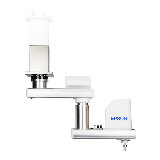
Industrial robot: scara robot
Hide thumbs
Also See for RS Series:
- Safety and installation (218 pages) ,
- Maintenance manual (122 pages)

Related Manuals for Epson RS Series


Summary of Contents for Epson RS Series
- Page 1 Industrial Robot: SCARA ROBOT RS series MANUAL Rev.4 ENM226R5362F Original instructions...
- Page 3 Industrial Robot: SCARA ROBOT RS series Manual Rev.4 Seiko Epson Corporation 2021-2022 RS series Rev.4...
- Page 4 Please notify us if you should find any errors in this manual or if you have any comments regarding its contents. MANUFACTURER CONTACT INFORMATION Contact information is described in “SUPPLIERS” in the first pages of the following manual: Robot System Safety Manual Read this manual first RS series Rev.4...
- Page 5 Please separate used batteries from other waste streams to ensure that it can be recycled in an environmentally sound manner. For more details on available collection facilities please contact your local government office or the retailer where you purchased this product. RS series Rev.4...
- Page 6 Before Reading This Manual This section describes what you should know before reading this manual. Structure of Control System The RS series Manipulators can be used with the following combinations of Controllers and software. Controller Software Name Structure Control Unit RC700-A EPSON RC+ 7.0 Ver.7.1.2 or greater...
- Page 7 - The method of firmware update and controller setting backup etc. EPSON RC+ 7.0 User’s Guide (PDF Manual) This manual describes general information about program development software. EPSON RC+ 7.0 SPEL+ Language Reference (PDF Manual) This manual describes the robot programming language “SPEL+”. Other Manual (PDF Manual) Manuals for each option are available.
- Page 8 RS series Rev.4...
-
Page 9: Table Of Contents
4.1 Attaching an End Effector ..............40 4.2 Attaching Cameras and Air valves ............. 42 4.3 Weight and Inertia Settings ..............42 4.3.1 Weight Setting ................42 4.3.2 Inertia Setting ................44 4.4 Precautions for Auto Acceleration/Deceleration of Joint #3 ....48 RS series Rev.4... - Page 10 RS3 Stopping Time and Stopping Distance When Safeguard Is Opened . 71 RS3-351*: J1 ..................71 RS3-351*: J2 ..................71 RS3-351*: J3 ..................71 RS4 Stopping Time and Stopping Distance When Safeguard Is Opened .72 RS4-551*: J1 ..................72 RS4-551*: J2 ..................72 RS4-551*: J3 ..................72 viii RS series Rev.4...
-
Page 11: Rs3, Rs4 Manipulator
RS3, RS4 Manipulator This volume contains information for setup and operation of the Manipulators. Please read this volume thoroughly before setting up and operating the Manipulators. -
Page 13: Safety
WARNING This symbol indicates that a danger of possible harm to people or physical damage to equipment and facilities exists if the associated instructions are not followed properly. CAUTION RS series Rev.4... -
Page 14: Design And Installation Safety
To ensure safety, a safeguard must be installed for the robot system. For details on the safeguard, refer to the Installation and Design Precautions in the Safety chapter of the EPSON RC+ User’s Guide. The following items are safety precautions for design personnel: ■... -
Page 15: Strength Of The Ball Screw Spline
Manipulator moves unexpectedly. ■ Immediately press the Emergency Stop switch whenever the Manipulator moves abnormally while the robot system is operated. RS series Rev.4... - Page 16 (Speed: approx. 5 to 20%) depending on combination of Arm orientation and end effector load. Oscillation arises from natural oscillation frequency of the Arm and can be controlled by following measures. Changing Manipulator speed Changing the teach points Changing the end effector load RS series Rev.4...
-
Page 17: Emergency Stop
Whether or not the reduction gear is damaged Whether or not the joints are in their proper positions If there is a position gap, perform calibration by referring to the RS series Maintenance Manual 13. Calibration in this manual. Before using the Emergency Stop switch, be aware of the followings. -
Page 18: Safeguard
Hand weight WEIGHT Setting ACCEL Setting Workpiece weight SPEED Setting Posture etc. For stopping time and stopping distance of the Manipulator, refer to “Appendix C: Stopping Time and Stopping Distance When the Safeguard is Opened”. RS series Rev.4... -
Page 19: Emergency Movement Without Drive Power
− Shaft (up and down) − Joint #4 (rotating) Be careful of the shaft while the brake release switch is pressed, NOTE because the shaft may be lowered by the weight of an end effector. RS series Rev.4... - Page 20 − switch Shaft (up and down) − Joint #4 (rotating) Be careful of the shaft while the brake release switch is pressed, NOTE because the shaft may be lowered by the weight of an end effector. RS series Rev.4...
-
Page 21: Accels Setting For Cp Motions
Z-axis height 0 (Origin point) If the Manipulator is operated in CP motion with the wrong set values, make sure to check the following point. Whether the ball screw spline shaft is deformed or bent RS series Rev.4... -
Page 22: Warning Labels
Do not enter the work space when the Manipulator is operating. It is extremely hazardous since the Arm may collide and cause serious safety problems, Hazardous voltage exists while the Manipulator is ON. To avoid electric shock, do not touch any internal electric parts. RS series Rev.4... - Page 23 (only UL model.) Location Label Label Indicates Product name, Model name, Manipulator’s serial No., Local codes information, Specification, Manufacturer, Importer, Date of manufacture, Country - of manufacture, etc. For details, refer to the attached label. RS series Rev.4...
- Page 24 RS3 RS4 Manipulator 1. Safety Location of Labels (UL: F) RS series Rev.4...
- Page 25 RS3 RS4 Manipulator 1. Safety (UL: F) RS series Rev.4...
-
Page 26: Response For Emergency Or Malfunction
Shaft switch − Joint #4 (Rotating) ■ While pressing the break release switch, not only Joint #3 but also Joint #4 may move due to its own weight. Be careful of the shaft falling or rotating. CAUTION RS series Rev.4... -
Page 27: Specifications
: 3 kg : 4 kg Environment Cleanroom-model This model has additional features that reduce dust emitted by the Manipulator to enable use in clean room environments. For details of the specifications, refer to Appendix A: Specifications. RS series Rev.4... -
Page 28: Part Names And Outer Dimensions
Performing any work with the power ON is extremely hazardous and it may result in electric shock and/or improper function of the robot system. Make sure to turn OFF the controller power before the maintenance work. RS series Rev.4... - Page 29 For manipulator mounting ø16h7 shaft diameter through hole ø30 mechanical stop diameter ø11 spot facing Enlarged view from A Reference through hole depth 6.5 (Original orientation of Joint #3, #4) (View from the top of the base) RS series Rev.4...
- Page 30 RS3 RS4 Manipulator 2. Specifications Cleanroom-model (RS3-351C) The following figures show the special parts for Cleanroom-model. These parts are different in appearance from Standard-model. Exhaust port Exhaust port Plate cover (For Anti-static) Bellows Bellows RS series Rev.4...
- Page 31 ø16h7 Shaft diameter ø11 spot facing ø30 Mechanical stop diameter ø53 Bellows outer diameter depth 6.5 Reference through hole (from back side) Enlarged view from A (View from the top of the base) (Original orientation of Joint #3, #4) RS series Rev.4...
-
Page 32: Rs4-551
ø 6 mm pneumatic tube Fitting (white) User Connector for ø 6 mm (15-pin D-sub Connector) Joint #3 pneumatic tube (up and down) − Shaft Joint #3 − brake release switch Joint #4 (rotating) LED lamp RS series Rev.4... - Page 33 6-6.5 through hole Mechanical stop diameter ø11 spot facing depth 6.5 (from back side) Reference through hole Enlarged view from A (View from the top of the base) (Original orientation of Joint #3, #4) RS series Rev.4...
- Page 34 RS3 RS4 Manipulator 2. Specifications Cleanroom-model (RS4-551C) The following figures show the special parts for Cleanroom-model. These parts are different in appearance from Standard-model. Exhaust port Exhaust port Plate cover (For Anti-static) Bellows Bellows RS series Rev.4...
- Page 35 ø11 spot facing depth 6.5 ø16h7 Shaft diameter (from back side) ø30 Mechanical stop diameter ø53 Bellows outer diameter Enlarged view from A Reference through hole (Original orientation of Joint #3, #4) (View from the top of the base) RS series Rev.4...
-
Page 36: Specifications
The custom specifications may require a different configuration procedure; check the custom specifications number (MT***) and contact the supplier of your region when necessary. The Manipulator model can be set from software. Refer to the chapter Robot Configuration in the EPSON RC+ User’s Guide. RS series Rev.4... -
Page 37: Environments And Installation
In such a case, it is recommended to warm up for about 10 minutes. RS series Rev.4... -
Page 38: Base Table
The Manipulator installation surface should have a flatness of 0.5 mm or less and an inclination of 0.5 ° or less. If the flatness of the installation surface is improper, the base may be damaged, or the robot may not fully show its performance. RS series Rev.4... - Page 39 When using a leveler to adjust the height of the base table, use a screw with M16 diameter or more. If you are passing cables through the holes on the base table, see the figures below. Controller M/C Signal Cable M/C Power Cable RS series Manipulator Power Cable Signal Cable Connector (Straight) Connector Power Cable Connector (L-shaped) The M/C cables are installed to the Manipulator body and cannot be removed.
- Page 40 refer to the Controller manual. ■ To ensure safety, a safeguard must be installed for the robot system. For details on the safeguard, refer to the EPSON RC+ User’s Guide. WARNING Base Table – Design Example The following is an example for designing the base table of RS3 Manipulator.
- Page 41 Length: 140 mm or more Width: 131 mm or more from the reference hole, or 69.6 mm or more from the reference hole [Unit: mm] A: Installation hole B: Positioning hole C: Outer dimension of Manipulator cover RS series Rev.4...
-
Page 42: Mounting Dimensions
RS3-351*: 175 mm RS4-551*: 275 mm Maximum range RS3-351* RS4-551* Arm #1 Length 175 mm 275 mm Arm #2 Length 175 mm 275 mm Joint #1 Motion range ± 225 degree Joint #2 Motion range ± 225 degree RS series Rev.4... -
Page 43: Unpacking And Transportation
■ Stabilize the Manipulator with your hands when hoisting it. ■ When transporting the Manipulator for a long distance, secure it to the delivery equipment directly so that the Manipulator never falls. If necessary, pack the Manipulator in the same style as it was delivered. RS series Rev.4... -
Page 44: Installation
■ When installing the Manipulator to the ceiling, support the Manipulator, and then secure the anchor bolts. Removing the support without securing the anchor bolts properly is extremely hazardous and may result in fall of the Manipulator. (1) Unpack the Manipulator with retaining the arm posture. RS series Rev.4... -
Page 45: Cleanroom-Model
Wipe off the dust on the Manipulator with a little alcohol or distilled water on a lint- free cloth. Transport the Manipulator into the cleanroom. Refer to the installation procedure of each Manipulator model and install the Manipulator. Connect an exhaust tube to the exhaust port. RS series Rev.4... -
Page 46: Connecting The Cables
Controller used. For details on the connection, refer to the Controller manual. CAUTION If the Manipulator G series, E2 series or RS series is connected to the Controller for the 6-axis, it may result in malfunction of the Manipulator. When the Manipulator is a Cleanroom-model, use it with an exhaust system. -
Page 47: User Wires And Pneumatic Tubes
(15-pin D-sub connector) * Color differs depending on the shipment time NOTE The Joint #4 (rotating) motion range is ±720 degrees. Be careful not to let the wires/tubes caught in the end effector. RS series Rev.4... -
Page 48: Relocation And Storage
Transport and store the Manipulator in the range of Temperature: −25 to +55°C, Humidity: 10 to 90% (no condensation). When condensation occurs on the Manipulator during transport or storage, turn ON the power only after the condensation dries. Do not shock or shake the Manipulator during transport. RS series Rev.4... -
Page 49: Relocation Procedure
Manipulator. Turn OFF the power on all devices and unplug the cables. Hold the bottom of Arm #1 by hand to unscrew the anchor bolts. Then, remove the Manipulator. RS3-351* RS4-551* Center of gravity Center of gravity RS series Rev.4... -
Page 50: Setting Of End Effectors
This button switch is a momentary-type; the brake is released only while the button switch is being pressed. - Be careful of the shaft falling while the brake release switch is being pressed because the shaft may be lowered by the weight of the end effector. RS series Rev.4... - Page 51 RS3 RS4 Manipulator 4. Setting of End Effectors RS3-351* RS4-551* Brake release switch The shaft may be lowered by the weight of the end effector. RS series Rev.4...
-
Page 52: Attaching Cameras And Air Valves
Manipulator, and/or shorten the life cycle of parts/mechanisms. The acceptable weight capacity (end effector and work piece) in RS series is 1 kg at the default rating and RS3-351*: 3 kg, RS4-551*: 4 kg at the maximum. - Page 53 : distance from rotation center of Joint #2 to center of gravity of camera etc. <Example> A “0.5 kg” camera is attached to the end of the RS series arm (250 mm away from the rotation center of Joint #2) with a load weight of “1 kg”.
-
Page 54: Inertia Setting
CAUTION excessive shock, insufficient function of the Manipulator, and/or shorten the life cycle of parts/mechanisms. The acceptable moment of inertia of load for a RS series Manipulator is 0.005 kgm at the default rating and 0.05 kgm at the maximum. When the moment of inertia of the load exceeds the rating, change the setting of the moment of inertia parameter of the Inertia command. - Page 55 Manipulator, and/or shorten the life cycle of parts/mechanisms. The acceptable eccentric quantity of load in RS series is 0 mm at the default rating and 100 mm at the maximum. When the eccentric quantity of load exceeds the rating, change the setting of eccentric quantity parameter of Inertia command.
- Page 56 Joint #3 shaft End effector (a) Work piece (c) Work piece (b) Whole moment Moment of inertia Moment of inertia Moment of inertia of inertia of work piece (c) of end effector (a) of work piece (b) RS series Rev.4...
- Page 57 + m × L (b) Moment of inertia of a cylinder Cylinder’s center of gravity Rotation center + m × L (c) Moment of inertia of a sphere Sphere’s center of gravity Rotation center + m × L RS series Rev.4...
-
Page 58: Precautions For Auto Acceleration/Deceleration Of Joint #3
Joint #3 RS3-351* RS4-551* -100 -140 (mm) Height of the shaft When moving the Manipulator horizontally while the shaft is being lowered, it may cause NOTE over-shoot at the time of final positioning. RS series Rev.4... -
Page 59: Motion Range
Manipulator does not move. The pulse range can be set on the [Range] panel shown by selecting [Tools]-[Robot EPSON Manager]. (You may also execute the Range command from the [Command Window].) RS series Rev.4... -
Page 60: Max. Pulse Range Of Joint #1
(+) and the clockwise pulse value is defined as the negative (-). View from this point A : Max. motion range : ± 225 ° B : Max. pulse range : − 4177920 to + 4177920 pulse RS series Rev.4... -
Page 61: Max. Pulse Range Of Joint #3
Arm #2. With the 0 pulse as a starting point, the counterclockwise pulse value is defined as the positive (+) and the clockwise pulse value is defined as the negative (-). 0 pulse ± 3145728 pulse View from this point RS series Rev.4... -
Page 62: Motion Range Setting By Joint #3 Mechanical Stops
(9) Move Joint #3 to its lower limit while pressing the brake release switch, and then check the lower limit position. Do not lower the mechanical stop too far. Otherwise, the joint may not reach a target position. RS series Rev.4... -
Page 63: Setting The Cartesian (Rectangular) Range In The Xy Coordinate System Of The Manipulator (For Joints #1 And #2)
The maximum physical range is based on the position of the mechanical stops. Set the XYLim setting on the [XYZ Limits] panel shown by selecting [Tools]-[Robot EPSON Manager]. (You may also execute the XYLim command from the [Command Window].) RS series Rev.4... -
Page 64: Standard Motion Range
Center of Joint #3 RS3-351S RS3-351C RS4-551S RS4-551C R350 R550 R175 R275 175 mm 275 mm Arm#1, Arm#2 length Joint #3 range to hit upper mechanical stop Joint #3 stroke Joint #3 range to hit lower mechanical stop RS series Rev.4... -
Page 65: Regular Inspection
Regular Inspection This volume contains maintenance procedures with safety precautions for RS series Manipulators. -
Page 67: General Maintenance For Rs3 Rs4
8 months (2000 h) √ 9 months (2250 h) √ √ 10 months (2500 h) √ 11 months (2750 h) √ 12 months (3000 h) √ √ √ √ 13 months (3250 h) √ √ 20000 h RS series Rev.4... -
Page 68: Inspection Point
If the shaft falls when in MOTOR OFF and the brake is not released, contact the supplier. Check that there is no unusual sound or vibration when operating. Check whether unusual sound or vibration occurs. If there is something wrong, contact the supplier. RS series Rev.4... -
Page 69: Overhaul (Parts Replacement)
Normal grease Discolored grease Perform greasing at 50 km of operation for the first time of greasing. For the EPSON RC+ 7.0 Ver. 7.2.x or later (firmware Ver.7.2.x.x or later), the NOTE recommended replacement time for the grease on the ball screw spline unit can be checked in the [Maintenance] dialog box of the EPSON RC+ 7.0. - Page 70 Arm #2 by the weight of the end effector. - Move the shaft to the lower limit manually while by selecting EPSON RC+ Joint #3 7.0 menu - [Tools] - [Robot Manager] - Break release switch [Jog &...
- Page 71 Run for about 5 minutes to spread the grease over the shaft. Turn OFF the controller. (10) Wipe off excess grease on the end of the spline nut and mechanical stop. End of the spline nut Figure: RS3-351* RS series Rev.4...
-
Page 72: Tightening Hexagon Socket Head Cap Bolts
Bolt hole two or three and fasten the bolts securely with a hexagonal wrench. Then, use a torque wrench so that the bolts are fastened with tightening torques shown in the table above. RS series Rev.4... -
Page 73: Appendix
Appendix This volume describes the specifications table for each model and detailed data of stopping time and stopping distance. -
Page 75: Appendix A: Specification
1 pneumatic tube (ø 4 mm): 0.59 MPa (6 kgf/cm : 86 psi) Environmental Ambient temperature 5 to 40°C requirements *4 Ambient relative humidity 10 to 80% RH (no condensation) Noise level LAeq = 70 dB (A) or under Applicable Controller RC700-A RS series Rev.4... - Page 76 Although values larger than 100 can be set to Accel, it is recommended to minimize the use of large values to necessary motions since operating the manipulator continuously with the large Accel setting may shorten the product life remarkably. RS series Rev.4...
-
Page 77: Appendix B: Stopping Time And Stopping Distance In Emergency
: Arm speed (Speed value) Vertical axis : Stopping time and stopping distance in each arm speed Time [sec] : Stopping time Distance [deg] : Stopping distance of J1 and J2 Distance [mm] : Stopping distance of J3 RS series Rev.4... -
Page 78: Rs3 Stopping Time And Stopping Distance In Emergency
100% Speed[%] Speed[%] RS3-351*: J3 1.0kg 2.0 kg 3.0 kg 1.0kg 2.0 kg 3.0 kg Weight[kg] Weight[kg] 0.50 100.0 90.0 0.40 80.0 70.0 0.30 60.0 50.0 0.20 40.0 30.0 0.10 20.0 10.0 0.00 100% 100% Speed[%] Speed[%] RS series Rev.4... -
Page 79: Rs4 Stopping Time And Stopping Distance In Emergency
Speed[%] RS4-551*: J3 1.0kg 3.0 kg 4.0 kg 1.0kg 3.0 kg 4.0 kg Weight[kg] Weight[kg] 1.00 140.0 0.90 120.0 0.80 100.0 0.70 0.60 80.0 0.50 60.0 0.40 0.30 40.0 0.20 20.0 0.10 0.00 100% 100% Speed[%] Speed[%] RS series Rev.4... -
Page 80: Appendix C: Stopping Time And Stopping Distance When Safeguard Is Opened
: Arm speed (Speed value) Vertical axis : Stopping time and stopping distance in each arm speed Time [sec] : Stopping time Distance [deg] : Stopping distance of J1 and J2 Distance [mm] : Stopping distance of J3 RS series Rev.4... -
Page 81: Rs3 Stopping Time And Stopping Distance When Safeguard Is Opened
100% Speed[%] Speed[%] RS3-351*: J3 1.0kg 2.0 kg 3.0 kg 1.0kg 2.0 kg 3.0 kg Weight[kg] Weight[kg] 0.50 100.0 90.0 0.40 80.0 70.0 0.30 60.0 50.0 0.20 40.0 30.0 0.10 20.0 10.0 0.00 100% 100% Speed[%] Speed[%] RS series Rev.4... -
Page 82: Rs4 Stopping Time And Stopping Distance When Safeguard Is Opened
Speed[%] RS4-551*: J3 1.0kg 3.0 kg 4.0 kg 1.0kg 3.0 kg 4.0 kg Weight[kg] Weight[kg] 1.00 140.0 0.90 120.0 0.80 100.0 0.70 0.60 80.0 0.50 60.0 0.40 0.30 40.0 0.20 20.0 0.10 0.00 100% 100% Speed[%] Speed[%] RS series Rev.4...