Table of Contents
Advertisement
Advertisement
Table of Contents

Related Manuals for Epson VT Series


Summary of Contents for Epson VT Series
- Page 1 6-Axis Robots VT series MANIPULATOR MANUAL Rev.1 EM18YR3817F...
- Page 3 6-Axis ROBOT VT series Manipulator Manual Rev.1 Copyright 2018 SEIKO EPSON CORPORATION. All rights reserved. VT Rev.1...
- Page 4 FOREWORD Thank you for purchasing our robot products. This manual contains the information necessary for the correct use of the manipulator. Please carefully read this manual and other related manuals before installing the robot system. Keep this manual handy for easy access at all times. WARRANTY The Manipulator and its optional parts are shipped to our customers only after being subjected to the strictest quality controls, tests, and inspections to certify its compliance...
- Page 5 TRADEMARKS Microsoft, Windows, and Windows logo are either registered trademarks or trademarks of Microsoft Corporation in the United States and/or other countries. Other brand and product names are trademarks or registered trademarks of the respective holders. NOTICE No part of this manual may be copied or reproduced without authorization. The contents of this manual are subject to change without notice.
- Page 6 For other countries, please contact your local government to investigate the possibility of recycling your product. The battery removal/replacement procedure is described in the following manuals: VT series manipulator manual Maintenance: 18.4 Replacing the Lithium Battery VT Rev.1...
- Page 7 Before Reading This Manual This section describes what you should know before reading this manual. Structure of Robot System The VT series Manipulators can be used with the following combinations of software. Controller Firmware VT6-A901S Ver.7.4.53.0 or later Before Ver.7.3.2 EPSON RC+ 7.0...
- Page 8 VT Rev.1...
-
Page 9: Table Of Contents
1.5.2 Release the Brake by the Software ........10 1.6 Precaution for Operation in Low Power Status ......... 10 1.7 Labels ....................11 2. Specifications 2.1 Features of VT series Manipulators ..........13 2.2 Model Number ................... 13 2.3 Part Names ..................14 2.4 Outer Dimensions ................15 2.5 Standard Motion Range .............. - Page 10 6.2 Switch Operation Mode ..............63 6.3 Program Mode (AUTO) ..............64 6.3.1 What is Program Mode (AUTO)? ........... 64 6.3.2 Setup from EPSON RC+ 7.0 ..........64 6.4 Auto Mode (AUTO) ................65 6.4.1 What is Auto mode (AUTO)? ..........65 6.4.2 Setup from EPSON RC+ 7.0 ..........
- Page 11 8.2.2 Adoptable USB Memory ............72 8.3 Controller Status Storage Function ........... 72 8.3.1 Controller Status Storage ............72 8.3.2 Load Data with EPSON RC+ 7.0 .......... 73 8.3.3 Transfer with E-mail ............... 74 8.4 Details of Data ................... 75 9.
- Page 12 TABLE OF CONTENTS 13. Standard I/O Connector 13.1 Input Circuit ..................93 13.1.1 Typical Input Circuit Application ........... 94 13.1.2 Typical Input Circuit Application 2 ........94 13.1.3 Pin Assignments of Input Circuit .......... 95 13.2 Output Circuit ................... 95 13.2.1 Typical Output Circuit Application 1 ........
- Page 13 TABLE OF CONTENTS Maintenance 1. Safety Maintenance 2. General Maintenance 2.1 Maintenance Inspection ..............116 2.1.1 Schedule for Maintenance Inspection ......... 116 2.1.2 Inspection Point ..............117 2.2 Overhaul (Parts Replacement) ............118 2.3 Tightening Hexagon Socket Head Cap Bolts........120 2.4 Matching Origins................
- Page 14 TABLE OF CONTENTS 8. Cable 8.1 Replacing Cable Unit ............... 148 8.2 Insert or Pull out of Power Cable ............. 164 9. Joint #1 9.1 Replacing Joint #1 Motor ..............166 9.2 Replacing Joint #1 Reduction Gear Unit .......... 170 9.3 Replacing Joint #1 Timing Belt ............
- Page 15 TABLE OF CONTENTS 16. LED Plate 16.1 Replacing LED Plate ..............226 17. Felt Sheet 17.1 Replacing Joint #2 Felt Sheet ............228 17.2 Replacing Joint #3 Felt Sheet ............229 18. Controller Unit 18.1 Replacing Controller Unit .............. 231 18.2 Replacing Power Board ..............
- Page 16 TABLE OF CONTENTS VT Rev.1...
-
Page 17: Setup & Operation
Setup & Operation This volume contains information for setup and operation of the VT series Manipulators. Please read this volume thoroughly before setting up and operating the Manipulators. -
Page 19: Safety
Setup & Operation 1. Safety 1. Safety Installation and transportation of manipulators and robotic equipment shall be performed by qualified personnel and should conform to all national and local codes. Please read this manual and other related manuals before installing the robot system or before connecting cables. -
Page 20: Design And Installation Safety
The following items are safety precautions for design personnel: ■ Personnel who design and/or construct the robot system with this product must read the Safety chapter in the EPSON RC+ User’s Guide to understand the safety requirements before designing and/or constructing the robot system. -
Page 21: Operation Safety
Setup & Operation 1. Safety 1.3 Operation Safety The following items are safety precautions for qualified Operator personnel: ■ Please carefully read the 1.3 Safety-related Requirements in the Safety chapter of the Safety and Installation manual before operating the robot system. Operating the robot system without understanding the safety requirements is extremely hazardous and may result in serious bodily injury and/or severe equipment damage to the robot system. - Page 22 Setup & Operation 1. Safety ■ Whenever possible, only one person should operate the robot system. If it is necessary to operate the robot system with more than one person, ensure that all people involved communicate with each other as to what they are doing and take all necessary safety precautions.
-
Page 23: Emergency Stop
For the Safeguard system, do not use the circuit for E-STOP. For details of the Safeguard system, refer to the following manuals. EPSON RC+ User’s Guide 2. Safety - Installation and Design Precautions - Safeguard System Safety and Installation 2.5 Connection to EMERGENCY Connector... - Page 24 Weight of the end effector Weight setting Weight of workpiece Speed setting Operating pose Accel setting Conditions for measurement VT series ACCEL Setting SPEED Setting Load [kg] WEIGHT Setting VT6-A901** Arm #1 Free...
-
Page 25: How To Move Arms With The Electromagnetic Brake
Setup & Operation 1. Safety 1.5 How to Move Arms with the Electromagnetic Brake When the electromagnetic brake is operating such as an emergency status, all arms cannot be moved. For procedures to release the electromagnetic brake, refer to the following section. When the electromagnetic brake is released, the arms can be moved by hand. -
Page 26: Release The Brake By The Software
Emergency Stop switch. Otherwise, you cannot immediately stop the arm falling due to an erroneous operation. The arm falling may cause equipment damage and/or malfunction of the Manipulator. EPSON After releasing the Emergency Stop switch, execute the following command in [Command Window]. -
Page 27: Labels
Setup & Operation 1. Safety 1.7 Labels The Manipulator has the following warning labels. The warning labels are attached around the locations where specific dangers exist. Be sure to comply with descriptions and warnings on the labels to operate and maintain the Manipulator safely. - Page 28 Setup & Operation 1. Safety Location Warning Label NOTE Signature label S/N (Serial Number) label Location of labels VT Rev.1...
-
Page 29: Specifications
2. Specifications 2.1 Features of VT series Manipulators The VT series Manipulators are controller integrated manipulators. The features of the VT series Manipulators are as follows: For Device design and tooling - There is no external controller No installation space required for an external controller. -
Page 30: Part Names
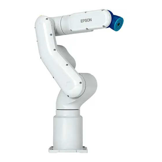
Setup & Operation 2. Specifications 2.3 Part Names LED Lamp (This lamp lights up Arm #4 Joint #4 while the motors are ON.) Arm #6 Arm #3 Joint #6 Joint #3 Arm #5 Joint #5 Arm #2 Joint #2 Arm #1 (Lower Arm) Joint #1 Base... -
Page 31: Outer Dimensions
Setup & Operation 2. Specifications 2.4 Outer Dimensions VT Rev.1... - Page 32 Setup & Operation 2. Specifications [Unit: mm] VT Rev.1...
-
Page 33: Standard Motion Range
Setup & Operation 2. Specifications 2.5 Standard Motion Range [Unit: mm] VT Rev.1... - Page 34 Setup & Operation 2. Specifications * P point : Intersection of the rotation centers for Joint #4, #5, and #6 : P point from top with Joint #3 declining −51 deg (Joint #2 center – P point center) : P point from top with Joint #3 tilting up +190 deg (Joint #2 center – P point center) : P point from lateral with Joint #3 declining +190 deg (Joint #1 center –...
-
Page 35: System Example
Windows 7 Professional Service Pack 1 Windows 8.1 Pro (EPSON RC+7.0 Ver.7.1.0 or later) Windows 10 Pro (EPSON RC+7.0 Ver.7.2.0 or later) *2 Either teaching pendant is available. *3 When connecting to VT series manipulators, specified convert cable is necessary. VT Rev.1... -
Page 36: Specifications
Setup & Operation 2. Specifications 2.7 Specifications Item Specifications Model Number VT6-A901S VT6-A901SR VT6-A901SW Model Name VT6L Mounting type *1 Table Top mounting Ceiling mounting Wall mounting Weight 40 kg : 89 lb. (not include the weight of cables or shipping jigs) Driving method All joints AC servo motor... - Page 37 (10000, 10000, 10000, 10000, 10000, 10000) Fine values) 65535, 65535, 65535, 65535, 65535, 65535 Weight 3 (6) Inertia 0.03 (0.1) Development EPSON RC+ 7.0 Environment Programming SPEL+ (multi-tasking robot language) Language Standard 6 joints simultaneous control Joint Control Digital AC servo control PTP (Point-To-Point control)
- Page 38 Setup & Operation 2. Specifications Item Specifications Display Mode Display LED TEACH, AUTO, PROGRAM, TestMode, Error, E-STOP Save to USB memory Controller Status Save Save in RC+ (PC) Voltage 100 ~ 240 VAC Phase Single phase Frequency 50 / 60 Hz Momentary Power Interrupt Less than 10 ms Rating Capacity...
-
Page 39: How To Set The Model
The custom specifications may require a different configuration procedure; check the custom specifications number (MT***) and contact us when necessary. The Manipulator model can be set from software. Refer to the chapter Robot Configuration in the EPSON RC+ User’s Guide. VT Rev.1... -
Page 40: Environments And Installation
Setup & Operation 3. Environments and Installation 3. Environments and Installation 3.1 Environmental Conditions A suitable environment is necessary for the robot system to function properly and safely. Be sure to install the robot system in an environment that meets the following conditions: Item Conditions Ambient temperature... -
Page 41: Base Table
I/O (Input) Connector (Unit: mm) TP Connector I/O(Output) Connector AC Power Connector ■ To ensure safety, a safeguard must be installed for the robot system. For details on the safeguard, refer to the EPSON RC+ User’s Guide. WARNING VT Rev.1... -
Page 42: Mounting Dimensions
Setup & Operation 3. Environments and Installation 3.3 Mounting Dimensions Mounting Area Be sure to have the following space available in addition to the space for mounting the Manipulator and peripheral equipment. Space for teaching points Space for maintenance and inspections (Ensure a space to open the covers and plates for maintenance.) Space for cables The minimum bend radius of the power cable is 90 mm. -
Page 43: Unpacking And Transportation
Setup & Operation 3. Environments and Installation 3.4 Unpacking and Transportation THE INSTALLATION SHALL BE PREFORMED BY QUALIFIED INSTALLATION PERSONNEL AND SHOULD CONFORM TO ALL NATIONAL AND LOCAL CODES. ■ Only authorized personnel should perform sling work and operate a crane and a forklift. -
Page 44: Installation Procedure
■ To ensure safety, a safeguard must be installed for the robot system. For details on the safeguard, refer to the Installation and Design Precautions in the Safety chapter of the EPSON RC+ User’s Guide. ■ Install the Manipulator in a location with sufficient space so that a tool or a work piece does not touch a wall or a safeguard when the Manipulator extends its arm fully while holding a work piece. -
Page 45: Power Supply
Setup & Operation 3. Environments and Installation 3.6 Power Supply ■ There is no power switch on the Manipulator. Right after inserting power plug to power, the Robot System turns ON. WARNING Be careful about electric shock when inserting power plug. 3.6.1 Specifications Ensure that the available power meets following specifications. -
Page 46: Breaker
Setup & Operation 3. Environments and Installation Use cable clamp on rear side of the Manipulator to fix AC power cable. AC Power Cable Clamp 3.6.3 Breaker Install an earth leakage circuit breaker or a circuit breaker in the AC power cable line. For the rated electric current of the circuit breaker, refer to the following set values. -
Page 47: Grounding
Setup & Operation 3. Environments and Installation 3.6.4 Grounding ■ Ground resistance must be 100 Ω or less. Improper ground resistance may result in fire and/or electric shock. ■ Do not use the ground line for the Manipulator in common with other ground lines or grounding electrodes for other electric power, motor power, welding devices, etc. -
Page 48: Connecting The Cables
Setup & Operation 3. Environments and Installation 3.7 Connecting the Cables ■ To shut off power to the robot system, disconnect the power plug from the power source. Be sure to connect the AC power cable to a power receptacle. DO NOT connect it directly to a factory power source. - Page 49 Setup & Operation 3. Environments and Installation (1) TP connector Connect the option Teach Pendant. For details, refer to the Setup & Operation 10.TP Port. (2) EMERGENCY The EMERGENCY connector has inputs to connect the Emergency Stop switch and the Safety Door switch. For safety reasons, connect proper switches for these input devices.
-
Page 50: Noise Countermeasures
Setup & Operation 3. Environments and Installation 3.7.2 Noise Countermeasures To minimize electrical noise conditions, the following items must be observed in the system’s cable wiring: - The earth wire of the power supply should be grounded. (Ground resistance: 100 Ω or less) It is important to ground the frame of Manipulator not only for prevention from electric shock, but also for reducing the influence of electric noise around the Manipulator. -
Page 51: Relocation And Storage
Setup & Operation 3. Environments and Installation 3.8 Relocation and Storage 3.8.1 Precautions for Relocation and Storage Observe the following when relocating, storing, and transporting the Manipulators. THE INSTALLATION SHALL BE PREFORMED BY QUALIFIED INSTALLATION PERSONNEL AND SHOULD CONFORM TO ALL NATIONAL AND LOCAL CODES. -
Page 52: Relocation
Setup & Operation 3. Environments and Installation Be sure to transport and store the robot system in environments that meet the following conditions: Item Conditions 0 to 45 °C Ambient temperature Ambient relative humidity 10 % to 80 % (no condensation) During unpacking and relocation, avoid applying external force to the arms and motors of the Manipulator. - Page 53 Setup & Operation 3. Environments and Installation Using Eyebolt Check that the eyebolts are securely fastened before transporting the Manipulator. After transporting the Manipulator, remove the eyebolts and keep them for future use. The eyebolts (accessory, 2 pcs) and wire must be strong enough to withstand the weight (See the figures below).
-
Page 54: Checking The Basic Orientation
Setup & Operation 3. Environments and Installation 3.9 Checking the Basic Orientation After parts have been replaced (motors, reduction gear units, belts, etc.), the Manipulator cannot operate properly because a gap exists between the origin positions stored in each motor and these stored in the Controller. The process to compensate the position gap is called “Calibration”. -
Page 55: Setting Of End Effectors
Setup & Operation 4. Setting of End Effectors 4. Setting of End Effectors 4.1 Attaching an End Effector Create an end effector for your Manipulator. Flange dimensions of the wrist attached to the end of Arm #6 is as below. ■... -
Page 56: Attaching Cameras And Air Valves
Setup & Operation 4. Setting of End Effectors 4.2 Attaching Cameras and Air Valves Decks are equipped to Arms #4 and #5 to enable the easy installation of air valve. To mount the camera, the camera plate unit is necessary. We provide the optional “Camera Plate Unit”. -
Page 57: Weight And Inertia Settings
The allowable load for VT series Manipulators is 6 kg at the maximum. Due to the limitations of the moment and inertia moment shown in the table below, the load (end effector weight + work piece weight) should also meet these conditions. - Page 58 Setup & Operation 4. Setting of End Effectors The moment M (Nm) and inertia moment I (kgm ) when the volume of the load (end effector + work piece) is small can be obtained by the following formula. M (Nm) = m(kg) × L (m) × g (m/s I (kgm ) = m(kg) ×...
- Page 59 Setup & Operation 4. Setting of End Effectors Example: Calculation of the critical dimension of the load (a) when the load is 6 kg. Center of gravity by the allowable moment control: 12.0 Nm/(6 kg×9.8 m/s ) = 0.204 m = 204 mm Center of gravity by the allowable inertia moment control: (0.3 kgm2/6 kg)1/2 = 0.223 m = 223 mm Due to the allowable moment control, center of gravity for the load limit is 212 mm from...
-
Page 60: Weight Setting
Manipulator, and/or shorten the life cycle of parts/mechanisms. The acceptable weight capacity (end effector and work piece) for VT series Manipulators is as follows: Rated... - Page 61 Setup & Operation 4. Setting of End Effectors Load on the Manipulator Mounting location of the load Arm #4 Deck Arm #5 Load on the fore Deck end of Arm #6 When you attach the equipment to the decks on the upper arm, convert its weight into equivalent weight assuming that the equipment is attached to the end of the Arm #6.
- Page 62 Setup & Operation 4. Setting of End Effectors Calculate the Weight parameter by using the formula below and enter the value. Weight Parameter Formula Weight parameter =M : Load on the fore end of Arm #6 (kg) : Equivalent weight of the Arm #4 deck (kg) : Equivalent weight of the Arm #5 deck (kg) /(L) /(L)
-
Page 63: Inertia Setting
CAUTION Manipulator. Also, the life cycle of parts is shortened and positional gap due to belt tooth bumping occurs. The acceptable inertia moment of load for VT series Manipulators is 0.01 kgm nominal rating and 0.1 kg·m maximum. Change the setting of the inertia moment according to the inertia moment of the load using the INERTIA command. - Page 64 Eccentric Quantity and the INERTIA Setting ■ The eccentric quantity of the load (weight of the end effector and work piece) must be 300 mm or less. The VT series Manipulators are not designed to work with eccentric quantity exceeding 300 mm.
- Page 65 Setup & Operation 4. Setting of End Effectors Automatic acceleration/deceleration setting by INERTIA (eccentric quantity) The percentage in the graph is based on the acceleration/ deceleration at rated eccentricity (0.03 kg·m2) as 100%. 0.05 0.10 (kg·m Inertia moment Moment of inertia Automatic acceleration/deceleration setting (kg·m setting by Inertia (moment of inertia) (%)
- Page 66 Setup & Operation 4. Setting of End Effectors Calculating the Inertia Moment Refer to the following example formulas to calculate the inertia moment of the load (end effector with work piece). The inertia moment of the entire load is calculated by the sum of (a), (b), and (c). Rotation Center End Effector (a) Work Piece (b)
-
Page 67: Precautions For Auto Acceleration/Deceleration Of Joint #3
Setup & Operation 4. Setting of End Effectors (c) Inertia moment of a sphere Sphere’s Center of Gravity Rotation Center + m × L Weight = m 4.4 Precautions for Auto Acceleration/Deceleration of Joint #3 The speed and acceleration/deceleration of the Manipulator motion are automatically optimized according to the values of WEIGHT and INERTIA and the Manipulator’s postures. -
Page 68: Motion Range
Manipulator does not move. The pulse range can be set in [Tools]-[Robot manager]-[Range] panel. EPSON You may also execute the Range command from the [Command Window]. VT Rev.1... -
Page 69: Max. Pulse Range Of Joint #1
Setup & Operation 5. Motion Range 5.1.1 Max. Pulse Range of Joint #1 Pulse values in counterclockwise direction are positive (+) and values in clockwise direction are negative (-). Arm #1 0 pulse position 5.1.2 Max. Pulse Range of Joint #2 Pulse values in clockwise direction are positive (+) and values in counterclockwise direction are negative (-). -
Page 70: Max. Pulse Range Of Joint #3
Setup & Operation 5. Motion Range 5.1.3 Max. Pulse Range of Joint #3 Pulse values in clockwise direction are positive (+) and values in counterclockwise direction are negative (-). Arm #3 0 pulse position 5.1.4 Max. Pulse Range of Joint #4 From the angle of arm end, clockwise pulse values are positive (+) and counterclockwise pulse values are negative (-). -
Page 71: Max. Pulse Range Of Joint #6
Setup & Operation 5. Motion Range 5.1.6 Max. Pulse Range of Joint #6 From the angle of arm end, clockwise pulse values are positive (+) and counterclockwise pulse values are negative (-). Arm #6 0 pulse position VT Rev.1... -
Page 72: Motion Range Setting By Mechanical Stops
Setup & Operation 5. Motion Range 5.2 Motion Range Setting by Mechanical Stops Using the adjustable mechanical stops (option) physically limits the absolute area that the Manipulator can move. Be sure to turn OFF the Manipulator in advance. Use bolts conforming to the specified length and surface processing (ex: nickel plating with high corrosion resistance. -
Page 73: Motion Range Setting Of Joint #2
Setup & Operation 5. Motion Range 5.2.2 Motion Range Setting of Joint #2 Install the adjustable mechanical stop (J2) to the threaded hole corresponding to the angle you want to set.) Hexagon socket head cap bolt M4 × 16×1 bolt Tightening torque 4.0 ±... -
Page 74: Motion Range Setting Of Joint #3
Setup & Operation 5. Motion Range 5.2.3 Motion Range Setting of Joint #3 Install the adjustable mechanical stop (J3) to the threaded hole corresponding to the angle you want to set.) Hexagon socket head cap bolt M4 × 16×1 bolt Tightening torque 4.0 ±... -
Page 75: Restriction Of Manipulator Operation By Joint Angle Combination
Setup & Operation 5. Motion Range 5.3 Restriction of Manipulator Operation by Joint Angle Combination To prevent the arms of the Manipulator from interfering each other, the Manipulator operation is restricted in the specified motion range according to the joint angle combination of the Arm #1, #2, and #3. -
Page 76: Coordinate System
5.4 Coordinate System The origin point is where the Manipulator’s installation face intersects with the rotation axis of Joint #1. For details on the coordinate system, refer to the EPSON RC+ User’s Guide manual. Table Top mounting Ceiling mounting Wall mounting... -
Page 77: Changing The Robot
Setup & Operation 5. Motion Range 5.5 Changing the Robot This section describes how to change the manipulator model on EPSON RC+. ■ Changing the manipulator should be done with great caution. It initializes the robot calibration parameters (Hofs, CalPls), additional axis information, and PG parameter data. -
Page 78: Setting The Cartesian (Rectangular) Range In The Xy Coordinate System Of The Manipulator
These settings are disabled during a joint jogging operation. Therefore, be careful not to allow the end effector to collide with the Manipulator or peripheral equipment. Set the XYLIM setting in [Tools]-[Robot manager]-[XYZ Limits] panel. EPSON You may also execute the XYLim command from the [Command Window]. VT Rev.1... -
Page 79: Operation Mode & Led
Setup & Operation 6. Operation Mode & LED 6. Operation Mode & LED 6.1 Overview The Robot system has three operation modes. TEACH mode This mode enables point data teaching and checking close to the Manipulator using the Teach Pendant. In this mode the Manipulator operates in Low power status. -
Page 80: Program Mode (Auto)
Follow the procedures below to switch to the Program mode. 6.3.2 Setup from EPSON RC+ 7.0 Switch the mode to Program mode from the EPSON RC+ 7.0. (1) Select EPSON RC+ 7.0 menu-[Setup]-[System Configuration] to display the [System Configuration] dialog. -
Page 81: Auto Mode (Auto)
Auto mode (AUTO) is for automatic operation of the Robot system. Procedures for switching to the Auto mode (AUTO) are the following. A : Set the start mode of the EPSON RC+ 7.0 to “Auto” and start the EPSON RC+ 7.0. -
Page 82: Setup From Control Device
Setup & Operation 6. Operation Mode & LED 6.4.3 Setup from Control Device Set the control device from EPSON RC+ 7.0. (1) Select EPSON RC+ 7.0 menu-[Setup]-[System Configuration] to display the [System Configuration] dialog. (2) Select [Controller]-[Configuration]. (3) Select [Control Device] to select the control device from the following two types. -
Page 83: Led
Setup & Operation 6. Operation Mode & LED 6.5 LED Six LEDs are located on the front panel of the Manipulator. LEDs (ERROR, E-STOP, TEACH, TEST, AUTO, PROGRAM) turn ON according to the Controller status (error, Emergency Stop, TEACH mode, Auto mode, Program mode). Controller status LED display 1. -
Page 84: Development Pc Connection Port
EPSON RC+ 7.0 User’s Guide 5.12.1 PC to Controller Communications Command. - Be sure to install the EPSON RC+ 7.0 to the development PC first, then connect the development PC and Manipulator with the USB cable. If Manipulator and the development PC are connected without installing the EPSON RC+ 7.0 to the development PC, [Add New Hardware Wizard] appears. -
Page 85: Precaution
7.3 Software Setup and Connection Check Connection of the development PC and the Manipulator is indicated. (1) Make sure that software EPSON RC+ 7.0 is installed to the Manipulator connected to the development PC. (Install the software when it is not installed. Refer to Robot System Safety and Installation or EPSON RC+ 7.0 User’s Guide. -
Page 86: Disconnection Of Development Pc And Manipulator
EPSON RC+ 7.0. 7.4 Disconnection of Development PC and Manipulator Disconnection of the development PC and the Manipulator communication. (1) Select the EPSON RC+ 7.0 menu-[Setup]-[PC to Controller Communications] to display the [PC to Controller Communications] dialog. (2) Click the <Disconnect> button. -
Page 87: Memory Port
8.1 What is Controller Status Storage Function? This function saves various kinds of Manipulator data to the USB memory. Data saved in USB memory is loaded to EPSON RC+ 7.0 to get the status of the Manipulator and the program simply and accurately. -
Page 88: Adoptable Usb Memory
Also, this function influences the Manipulator cycle time and the communication CAUTION with EPSON RC+ 7.0. Other than only when it is necessary, do not execute this function when operating the Manipulator. Use this procedure to save the status of the Manipulator to USB memory. -
Page 89: Load Data With Epson Rc+ 7.0
Setup & Operation 8. Memory Port 8.3.2 Load Data with EPSON RC+ 7.0 The following shows the procedure to load the data stored in the USB memory by EPSON RC+ 7.0 and display the Controller status. (1) Insert the USB memory into the PC with EPSON RC+ 7.0. -
Page 90: Transfer With E-Mail
(3) Send all the folders by e-mail. NOTE Delete files that do not relate to the project before transfer. This function is used to send the data to the system director and EPSON from the end users for problem analysis. VT Rev.1... -
Page 91: Details Of Data
VXDWORK.bin All files related to Project When [Include project files when status exported] check project except box is checked in EPSON RC+ 7.0 menu-[Setup]- ProjectName.obj *1 [System Configuration]-[Controller]- [Preference], the project file is stored. Includes program files. *1 Storage of “All files related to project except ProjectName.obj” can be specified by a setting. -
Page 92: Lan (Ethernet Communication) Port
Command (Setup Menu) for other details for the development PC and Manipulator connection. - For Ethernet (TCP/IP) communication with robot application software, refer to EPSON RC+ 7.0 Online Help or User’s Guide 14. TCP/IP Communications. LAN (Ethernet Communication) Port 9.1 What is the LAN (Ethernet Communication) Port Ethernet communication port supports 100BASE-TX / 10 BASE-T. -
Page 93: Changing Manipulator Ip Address
(1) For connection between the development PC and the Manipulator. Refer to Setup & Operation: 7. Development PC Connection Port. (2) Select the EPSON RC+ 7.0 menu-[Setup]-[Controller] to display the following dialog. (3) Select [Controller]-[Configuration]. (4) Enter the proper IP address and subnet mask and click the <Apply> button. -
Page 94: Connection Of Development Pc And Manipulator With Ethernet
(1) Connect the development PC and the Manipulator using the Ethernet cable. (2) Turn on the Manipulator. (3) Start EPSON RC+ 7.0. (4) Display the [PC to Controller Communication] dialog from [Setup] in EPSON RC+ 7.0 menu. (5) Click the <Add> button. - Page 95 [Connection status:]. Make sure that “Connected” is displayed and click the <Close> button to close the [PC to Controller Communications] dialog. Connection between the development PC and the Manipulator is complete. Now the robot system can be used via an Ethernet connection from EPSON RC+ 7.0. VT Rev.1...
-
Page 96: Disconnection Of Development Pc And Manipulator With Ethernet
9.5 Disconnection of Development PC and Manipulator with Ethernet Disconnection of the development PC and the Manipulator is shown below. (1) Display [PC-Controller Connection] dialog from [Setup] in EPSON RC+ 7.0 menu. (2) Click the <Disconnect> button. Communication between the Manipulator and the development PC is disconnected and the Ethernet cable can be removed. -
Page 97: Tp Port
TP Port The TP port connects the Teach Pendant (TP2, TP3) to the manipulator. Dedicated convert cable* is necessary if connecting TP2 to VT series manipulator. Contact to regional office if only convert cable is necessary. * TP Exchange Cable: R12NZ900L6 When nothing is connected to the TP port, Emergency Stop status occurs in the ... -
Page 98: Options
11.2 Tool Adapter (ISO flange) 11.3 Adjustable Mechanical Stops 11.4 External Wiring Kit 11.1 Camera Plate Unit To mount a camera to the VT series manipulator, the camera plate unit is requried. Parts included Qty. Camera adapter plate Camera mid plate Camera base plate Hexagon socket head screws M4×12... - Page 99 Camera and VT series Manipulator Joint #5 motion range (reference values) The Joint #5 motion range varies depending on the mounting position of camera mid plate and the camera you are using.
-
Page 100: Tool Adapter (Iso Flange)
11.2 Tool Adapter (ISO flange) Using the tool adapter, you can mount the end effector whose dimensions are designed for the ISO flange to the VT series Manipulators. For more details on the installation procedures, please contact the supplier of your region. -
Page 101: Adjustable Mechanical Stops
Setup & Operation 11. Options 11.3 Adjustable Mechanical Stops This option is used to mechanically limit the motion range of the Manipulator. For installation and angle restriction measures, refer to Setup & Operation 5.2 Motion Range Setting by Mechanical Stops. Adjustable mechanical stop (J1) Qty. -
Page 102: Emergency
Setup & Operation 12. EMERGENCY 12. EMERGENCY NOTE The details of safety requirements for this section are described in EPSON RC+ 7.0 User’s Guide 2. Safety. Please refer to them to keep the robot system safe. Make sure that emergency stop or safeguard operate properly before operating, not only booting but also usage changed such as options added or parts replaced as maintenance. -
Page 103: Safeguard Switch And Latch Release Switch
Setup & Operation 12. EMERGENCY 12.1 Safeguard Switch and Latch Release Switch The EMERGENCY connector has input terminals for the Safeguard switch and the Emergency Stop switch. Be sure to use these input terminals to keep the system safe. Connector Standard D-Sub 25 pin female (cable side) EMERGENCY connector... -
Page 104: Checking Latch Release Switch Operation
Setup & Operation 12. EMERGENCY When the latched TEACH mode is released while the safeguard is open, the status of NOTE Manipulator power is operation-prohibited because the safeguard is open at that time. To execute a Manipulator operation, close the safeguard again, and then close the latch release input. -
Page 105: Checking Emergency Stop Switch Operation
Setup & Operation 12. EMERGENCY 12.2.2 Checking Emergency Stop Switch Operation Once the Emergency Stop switch is connected to the EMERGENCY connector, continue the following procedure to make sure that the switch functions properly. For the safety of the operator, the Manipulator must not be powered ON until the following test is completed. -
Page 106: Pin Assignments
Setup & Operation 12. EMERGENCY 12.3 Pin Assignments The EMERGENCY connector pin assignments are as follows: (D-Sub 25 pin male) Signal Pin No. Function Pin No. Signal Function ESW11 ESW21 Emergency Stop switch contact (1) Emergency Stop switch contact (2) ESW12 ESW22 Emergency Stop switch contact (1) -
Page 107: Circuit Diagrams
Setup & Operation 12. EMERGENCY 12.4 Circuit Diagrams 12.4.1 Example 1: External emergency stop switch typical application External Emergency Manipulator Stop switches +24V Emergency Stop switch of an Operation Unit (TP) ESTOP1+ ESTOP2+ Main Circuit Control Be careful of the direction of voltage application −... -
Page 108: Example 2: External Safety Relay Typical Application
Setup & Operation 12. EMERGENCY 12.4.2 Example 2: External safety relay typical application Manipulator External +24V Fuse +24V Emergency Stop switch of an Operation Unit (TP) External +24V External +24V External safety relay Main Circuit (The above diagram Control is simplified for representation.) * For the protection of the emergency stop circuit,... -
Page 109: Standard I/O Connector
Setup & Operation 13. Standard I/O Connector 13. Standard I/O Connector Be careful not to exceed rated current range or rated current which are defined in manual. CAUTION If exceeding rated current, the Manipulator may now operate at worst. Standard I/O Connector is a connector mounted on back side of the Manipulator for connecting your input/output equipment to the system. -
Page 110: Typical Input Circuit Application
Setup & Operation 13. Standard I/O Connector 13.1.1 Typical Input Circuit Application Standard I/O (Input) Connector GND +DC 5 Input No.0 to 7 common 1 Input No.0 15 Input No.1 (Same) 2 Input No.2 (Same) 16 Input No.3 (Same) 3 Input No.4 (Same) 17 Input No.5 (Same) -
Page 111: Pin Assignments Of Input Circuit
Setup & Operation 13. Standard I/O Connector 13.1.3 Pin Assignments of Input Circuit Signal Name Signal Name Pin No. Pin No. Input No. 0 (Start) Input No. 1 (SelProg1) Input No. 2 (SelProg2) Input No. 3 (SelProg4) Input No. 4 (Stop) Input No. -
Page 112: Typical Output Circuit Application 1
Setup & Operation 13. Standard I/O Connector 13.2.1 Typical Output Circuit Application 1 Standard I/O (Output) Connector 1 Output No.0 Load Output No.1 (Same) Output No.2 (Same) Output No.3 (Same) Output No.4 (Same) Output No.5 (Same) Output No.6 (Same) Output No.7 (Same) Output No.0 to 7 Common... -
Page 113: Pin Assignments Of Output Circuit
Setup & Operation 13. Standard I/O Connector 13.2.3 Pin Assignments of Output Circuit Pin No. Signal Name Pin No. Signal Name Output No. 0 (Ready) Output No.1 (Running) Output No.2 (Paused) Output No.3 (Error) Output No.4 (EstopOn) Output No.5 (SafeguardOn) Output No.6 (SError) Output No.7 (Warning) Output common No. -
Page 114: I/O Cable Product Procedure
Setup & Operation 13. Standard I/O Connector 13.3 I/O Cable Product Procedure The following describes I/O cable product procedure for connecting user’s input/output devices. 13.3.1 I/O Cable Connecting Method (1) Prepare for I/O connector and cable which are included with shipment. Adaption cable: Electric wire capacity: 0.14 to 0.5mm Wire type: single wire, stranded wire, stranded wire with rod terminal. -
Page 115: I/O Remote Settings
Configuration in EPSON RC+ 7.0 User’s Guide - Remote Control. For details about I/O cable connection, refer to sections on Setup & Operation 13: Standard I/O Connector and 17. Fieldbus I/O. For details about communication with external equipment, refer to EPSON RC+ 7.0 User’s Guide -12. Remote Control. ... -
Page 116: I/O Signal Description
14.1 I/O Signal Description Remote function is initially assigned to both input and output from 0 to 7. To change the function assignment from the initial setting, use EPSON RC+ 7.0. To use all signals, you will need to add Fieldbus I/O module. - Page 117 Setup & Operation 14. I/O Remote Settings Input Acceptance Name Initial Description Condition (*1) SelRobot1 SelRobot2 Specify the number of manipulator which SelRobot4 Not set executes a command. (*5) SelRobot8 SelRobot16 Ready output ON EStopOn output OFF SetMotorsOn Not set Turn ON manipulator motors.
- Page 118 For details, refer to EPSON RC+ 7.0 Online Help or Motor in SPEL Language Reference. (*7) For details, refer to EPSON RC+ 7.0 Online Help or MCal in SPEL Language Reference. (*8) This is for experienced users only. Make sure that you fully understand the input specification before using.
- Page 119 Preferences (1): “Motor power low when ForcePowerLow signal OFF” Preferences (2): “ForcePowerLow signal change pauses all tasks” For details of the manipulator preferences, refer to EPSON RC+ 7.0 User’s Guide [Setup]-[System Configuration]-[Controller]-[Preferences] in 5.12.2 [System Configuration] Command (Setup Menu).
-
Page 120: Remote Output Signals
Setup & Operation 14. I/O Remote Settings 14.1.2 Remote Output Signals Remote output is a function to output a status of the Manipulator or operation mode. Remote outputs provide the assigned function using with any control device The outputs execute automatically. Therefore, no special programming is needed. Name Initial Description... - Page 121 Setup & Operation 14. I/O Remote Settings Name Initial Description InsidePlane1 Turns ON when the manipulator is in the approach check Not set plane. (*4) InsidePlane15 Alarm Turns ON when any of the alarms is occurring. (*9) Not set Turns ON when a battery alarm of the manipulator is Alarm1 Not set occurring.
- Page 122 - The setting is Auto mode and the control device is remote. - The setting is Program mode and Remote I/O is enabled. (*3) For details, refer to EPSON RC+ 7.0 Online Help or Box in SPEL Language Reference. (*4) For details, refer to EPSON RC+ 7.0 Online Help or Plane in SPEL Language Reference.
-
Page 123: Timing Specifications
Setup & Operation 14. I/O Remote Settings 14.2 Timing Specifications 14.2.1 Precautions for Remote Input Signals The following charts indicate the timing sequences for the primary operations of the Controller. The indicated time lapses (time durations) should be referred to only as reference values since the actual timing values vary depending on the number of tasks running, as well as CPU speed of the Manipulator. -
Page 124: Timing Diagram For Safety Door Input Sequence
Setup & Operation 14. I/O Remote Settings 14.2.4 Timing Diagram for Safety Door Input Sequence Running 1066 Output Paused 1066 Output SafeguardOn Output MotorsOn Output Safety Input Latch Input Continue Input 14.2.5 Timing Diagram for Emergency Stop Sequence Running Output MotorsOn Output EStopOn... -
Page 125: Sd Card Slots
Setup & Operation 15. SD Card Slots 15. SD Card Slots Do not use any SD card other than accessories. If using other SD card, system may not operate properly. SD card is only available for robot system. CAUTION SD card is written only for robot system. - Page 126 Setup & Operation 16. RESET Switch 16. RESET Switch RESET Switch RESET switch has following function. Manipulator reboot Push the RESET switch for three seconds when booting the manipulator. Manipulator reboots. Shape of RESET switch is difficult to push. Use a sharp edged object when pushing the RESET switch.
- Page 127 Setup & Operation 17. Fieldbus I/O 17. Fieldbus I/O Fieldbus I/O of the VT series supports the following model. DeviceNet™ CC-Link PROFIBUS-DP PROFINET EtherNet/IP™ EtherCAT® For details, refer to the following manual. Robot Controller RC700 / RC90 Option Fieldbus I/O ■...
- Page 128 Setup & Operation 17. Fieldbus I/O Fieldbus Turn OFF the Manipulator. I/O Module Remove the optional slot cover on the back side of the Manipulator. Installation Sems bolt: 2-M3×6 Optional slot cover Inset the fieldbus I/O module to the optional slot. ...
-
Page 129: Maintenance
Maintenance This volume contains maintenance procedures with safety precautions for VT series Manipulators. -
Page 131: Safety Maintenance
Maintenance 1. Safety Maintenance 1. Safety Maintenance Please read this chapter, this manual, and other relevant manuals carefully to understand safe maintenance procedures before performing any routine maintenance. Only authorized personnel who have taken safety training should be allowed to maintain the robot system. -
Page 132: General Maintenance
Maintenance 2. General Maintenance ■ Be sure to connect the cables properly. Do not allow unnecessary strain on the cables. (Do not put heavy objects on the cables. Do not bend or pull the cables forcibly.) The unnecessary strain on the cables may result in damage to the cables, disconnection, and/or contact failure. -
Page 133: Inspection Point
Measure the accuracy repeatedly by √ a dial gauge when positional gap Whole occurs. Execute Brake off command (brake off, joint #) from the command window of the EPSON RC+ while the √ motors are OFF, and then check the √ √ √ √... -
Page 134: Overhaul (Parts Replacement)
Manipulator. NOTE For EPSON RC+ 7.0, the recommended replacement time for the parts subject to maintenance (motors, reduction gear units, and timing belts) can be checked in the [Maintenance] dialog box. Refer to the Maintenance: 4. Alarm. - Page 135 The manipulator operation hours can be checked in [Controller Status Viewer] dialog -[Motor On Hours]. (1) Select EPSON RC+ menu-[Tools]-[Controller] to open the [Controller Tools] dialog. (2) Click the <View Controller Status> button to open the [Browse For Folder] dialog.
-
Page 136: Tightening Hexagon Socket Head Cap Bolts
Then, follow the steps below to display the pulse values and record them. Execute the following command from the [Command Window]. EPSON >PULSE PULSE: [Joint #1 Pulse value] pls [Joint #2 Pulse value] pls [Joint #3 Pulse value] pls [Joint #4 Pulse value] pls[Joint #5 Pulse value]pls [Joint #6 Pulse value]pls VT Rev.1... -
Page 137: Layout Of Maintenance Parts
Maintenance 2. General Maintenance 2.5 Layout of Maintenance Parts LED Plate Joint #4 Reduction Gear Unit Joint #6 Motor Joint #4 Electromagnetic Brake Joint #4 Motor Joint #5 Motor Joint #4 Timing Belt Joint #2 Joint #1 Motor Reduction Gear Unit Joint #1 Reduction Gear Unit Joint #1 Electromagnetic Brake... -
Page 138: Manipulator Structure
Maintenance 3. Manipulator Structure 3. Manipulator Structure VT Rev.1... -
Page 139: Alarm
Maintenance 4. Alarm 4. Alarm When the lithium batteries run out, a voltage reduction alarm warning occurs. However, the warning does not guarantee that the battery lasts until you replace it. Therefore, you need to replace the battery immediately. If the battery has run out, the manipulator parameters will be lost and recalibration of the manipulator will be required. -
Page 140: Maintenance
Initial installation : Maintenance is enabled. Upgrade : Maintenance inherits the previous data. (Disables as default) For details for enabling or disabling the Maintenance, refer to the EPSON RC+ 7.0 User’s Guide 5.12.2 [System Configuration] Command (Setup Menu) - [Setup]-[System Configuration]-[Controller]-[Preferences] Page. NOTE ... -
Page 141: Maintenance Information
Maintenance 4. Alarm 4.2 Maintenance Information 4.2.1 How to Check the Maintenance Information The configured Maintenance information can be checked in the EPSON RC+. (1) Select EPSON RC+ 7.0 menu-[Tools]-[Maintenance] to display the [Controller Tools] dialog box. (2) To check the controller Maintenance information, click the <Maintenance> button and display the [Maintenance] dialog box. -
Page 142: How To Edit The Maintenance Information
L10 life is displayed as 100%. 4.2.2 How to Edit the Maintenance Information The configured Maintenance information can be edited in the EPSON RC+. (1) Select the EPSON RC+ 7.0 menu-[Tools]-[Maintenance] to display the [Controller Tools] dialog box. -
Page 143: Alarm Notifying Method
SPEL+ Language Reference SPEL+ Error Message The alarm notifying method can be configured by the output bit of the Remote I/O. The Remote I/O can be configured in the EPSON RC+ 7.0- [Setup] - [System Configuration] - [Controller] - [Remote Control]. -
Page 144: Backup And Restore
For some problems, backup may not be available before maintenance has to be performed. Be sure to backup the data after making changes, before problems occur. “Controller Status Storage” is one of the VT series Manipulator functions. It saves the NOTE ... -
Page 145: Backup
Maintenance 5. Backup and Restore 5.3 Backup Backup the Manipulator status from EPSON RC+ 7.0. (1) Select EPSON RC+ 7.0 menu-[Tools]-[Controller] to display the [Controller Tools] dialog. (2) Click the <Backup Controller…> button to display the [Browse For Folder] dialog. -
Page 146: Restore
■ Do not edit the backup files. Otherwise, operation of the robot system after CAUTION data restoration to the Manipulator is not assured. (1) Select the EPSON RC+ 7.0 menu-[Tools]-[Controller] to display the [Controller Tools] dialog. (2) Click the <Restore Controller…> button to display the [Browse For Folder] dialog. - Page 147 The default is unchecked. When a project is restored, the values of Global Preserve variables are loaded. For details about Global Preserve variable backup, refer to the following manual. EPSON RC+ 7.0 User’s Guide 5.10.10 Display Variables Command (Run Menu). Vision hardware configuration This checkbox allows you to restore the vision hardware configuration.
- Page 148 Click the <No> button (do not restore data) except for special situations such a manipulator replacement. NOTE When restoring the backup including the robot information other than VT series, an error occurs. You cannot restore the backup including T series robot created in the virtual controller of NOTE ...
-
Page 149: Firmware Update
EPSON RC+ 7.0 is always saved in the Manipulator. Firmware is supplied by CD-ROM as needed. Please contact us for information. You must use a PC running EPSON RC+ 7.0 connected to a Manipulator with USB to update the Manipulator firmware. - Page 150 Maintenance 6. Firmware Update (6) Make sure that the development PC is connected to the Manipulator with a USB cable and Click the <Next> button. (7) Check the current firmware version and the new firmware version and click the <Install> button. (8) The firmware upgrade starts.
-
Page 151: Manipulator Recovery
Maintenance 6. Firmware Update (10) The following dialog appears when transfer has completed. Click the <Next> button to reboot the Manipulator. (11) The following dialog appears after the Controller reboot. Click the <Finish> button. The firmware upgrade is complete. When you install the firmware (Ver.7.4.0.2 or later) on the controller which the firmware NOTE ... -
Page 152: Firmware Initialization Procedure
(1) Connect the development PC to the Manipulator with a USB cable (the firmware cannot be changed with an Ethernet connection). (2) Turn ON the Manipulator. Do not start the development software EPSON RC+ 7.0 until firmware initialization is complete. - Page 153 (10) The following dialog appears after the Manipulator reboot. Click the <Finish> button. The firmware upgrade is completed. Start EPSON RC+ 7.0 and restore the Controller settings. For details of restoring the operating system, refer to Maintenance 5. Backup and Restore. NOTE ...
-
Page 154: Covers
Maintenance 7. Covers 7. Covers All procedures for removing and installing covers in maintenance are described in this chapter. ■ Do not connect or disconnect the motor connectors while the power to the robot system is turned ON. Connecting or disconnecting the motor connectors with the power ON is extremely hazardous and may result in serious bodily injury as the Manipulator may move abnormally, and also may result in electric shock and/or malfunction of the robot system. -
Page 155: Arm #1 Cover
Maintenance 7. Covers 7.1 Arm #1 Cover ■ Do not remove the cover forcibly. Removing the cover forcibly may result in damage to the cables, disconnection, and/or contact failure. Damaged cables, disconnection, or contact failure is extremely hazardous and may result in electric shock and/or improper function of the robot system. -
Page 156: Arm #2 Cover
Maintenance 7. Covers 7.2 Arm #2 Cover ■ Do not remove the cover forcibly. Removing the cover forcibly may result in damage to the cables, disconnection, and/or contact failure. Damaged cables, disconnection, or contact failure is extremely hazardous and may result in electric shock and/or improper function of the robot system. -
Page 157: Arm #3 Cover
Maintenance 7. Covers 7.3 Arm #3 Cover ■ Do not remove the cover forcibly. Removing the cover forcibly may result in damage to the cables, disconnection, and/or contact failure. Damaged cables, disconnection, or contact failure is extremely hazardous and may result in electric shock and/or improper function of the robot system. -
Page 158: Arm #4 Cover 1
Maintenance 7. Covers 7.4 Arm #4 Cover 1 ■ Do not remove the cover forcibly. Removing the cover forcibly may result in damage to the cables, disconnection, and/or contact failure. Damaged cables, disconnection, or contact failure is extremely hazardous and may result in electric shock and/or improper function of the robot system. -
Page 159: Arm #4 Cover 2
Maintenance 7. Covers 7.5 Arm #4 Cover 2 ■ Do not remove the cover forcibly. Removing the cover forcibly may result in damage to the cables, disconnection, and/or contact failure. Damaged cables, disconnection, or contact failure is extremely hazardous and may result in electric shock and/or improper function of the robot system. - Page 160 Maintenance 7. Covers Arm #4 Cover 2 (1) Unscrew the mounting bolts, and then lift the Arm #4 Cover 2. Removal NOTE Do not remove the cover forcibly when removing it. (2) Disconnect the connector from the board mounted on the rear side of the Arm #4 Cover 2.
-
Page 161: Power Cable Cover
Maintenance 7. Covers 7.6 Power Cable Cover 2-M4×8 Sems Power Cable Cover Power Cable Unscrew the mounting bolts, and then lift the Power Cable Cover. Cover Removal Power Cable Put the Power Cable Cover to the connector plate and secure with the mounting bolts. Cover Hexagon socket head cap bolts with captive washer: 2-M4×8 Sems Installation... -
Page 162: Connector Plate
Maintenance 7. Covers 7.7 Connector Plate ■ Do not remove the connector plate forcibly. Removing the connector plate forcibly may result in damage to the cables, disconnection, and/or contact failure. Damaged cables, disconnection, or contact failure is extremely hazardous and may result in electric shock and/or improper function of the robot system. -
Page 163: Cable
Maintenance 8. Cable 8. Cable ■ Do not connect or disconnect the motor connectors while the power to the robot system is turned ON. Connecting or disconnecting the motor connectors with the power ON is extremely hazardous and may result in serious bodily injury as the Manipulator may move abnormally, and also may result in electric shock and/or malfunction of the robot system. -
Page 164: Replacing Cable Unit
Maintenance 8. Cable 8.1 Replacing Cable Unit Name Quantity Note Maintenance Cable Unit 2191349 part width across flats: 2.5 mm For M3 hexagon socket head Hexagonal cap bolts wrench width across flats: 3 mm For M4 hexagon socket head cap bolts Tools Torque wrench For tightening torque control... - Page 165 Maintenance 8. Cable Cable Unit (1) Move the Manipulator to the origin posture (0 pulse position). Removal (2) Turn OFF the Manipulator. (3) Remove the following covers and plate. Arm #1 Cover Arm #2 Cover Arm #3 Cover Arm #4 Cover 1 Arm #4 Cover 2 Connector Plate Reference: Maintenance 7 Covers...
- Page 166 Maintenance 8. Cable (6) Disconnect the following connectors of the controller unit. A: Power cable connector B: Signal cable connector C: Hand I/O connector D: LED connectors × 2 (7) Remove the ground wire terminals inside the base. Cross recessed head screws: M4×6 (8) Cut off the wire tie bound to the plate inside the base.
- Page 167 Maintenance 8. Cable (11) Disconnect the power cable connecter from the AMP board of Joint #1 motor. (12) Disconnect the signal cable connectors (for motor × 2) of Joint #1 motor. × (13) Cut off the wire ties bound to inside the Arm #2. Wire ties : AB150 ×6 Wire ties...
- Page 168 Maintenance 8. Cable (15) Remove the ground wire terminals of Arm #2. Cross recessed head screws: 2-M4×6 (16) Remove the Joint #2 motor. Reference: Maintenance 10.1 Replacing Joint #2 Motor (17) Remove the Joint #3 motor. Reference: Maintenance 11.1 Replacing Joint #3 Motor (18) Remove the light guide plate.
- Page 169 Maintenance 8. Cable (20) Disconnect the connector which is connected to the LED board. Connector: LED_CN1 Pass through the (21) Pass the LED cable through the opening of opening the Arm #2 and pull the LED cable out. (22) Cut off the wire tie bound to the plate inside the Arm #3.
- Page 170 Maintenance 8. Cable (25) Disconnect the power cable connecter from the AMP board of Joint #4 motor. (26) Disconnect the signal cable connectors (for motor × 2) of Joint #4 motor. (27) Cut off the wire ties bound to the plate inside the Arm #4.
- Page 171 Maintenance 8. Cable (31) Pass the ground wire and the following cables of each arm through the sleeve of each joint and pull them out. Ground wires × 4 Signal cables (for motor × 5) LED cable × 1 (32) Pass the power cable through the sleeve of each joint and pull it out in the following order.
- Page 172 Maintenance 8. Cable (1) Pass the new power cable in the following order. Cable Unit Installation Base → Arm #1 → Joint #1 Timing Belt Base side → Arm #2 → Arm #3 → Joint #4 Timing Belt → Arm #4 NOTE ...
- Page 173 Maintenance 8. Cable (7) Fix the ground wire between the base and the Arm #1. Cross recessed head screws: 2-M4×6 Tightening torque: 2.0 ± 0.1 N·m Base side: Ground wire terminal marked “BASE” on the wire marker. Arm #1 side: Ground wire terminal marked “ARM1”...
- Page 174 Maintenance 8. Cable (10) Fix the ground wire between the Arm #3 and the Arm Cross recessed head screws: 2-M4×6 Tightening torque: 2.0 ± 0.1 N·m Arm #3 side: Ground wire terminal marked “ARM3” on the wire marker. Arm #4 side: Ground wire terminal marked “ARM4”...
- Page 175 Maintenance 8. Cable (15) Pass the wire tie through the hole inside the base. Bind the following cables and the ground wire with the wire tie. Wire tie: AB150 Power cable LED cable Signal cable (for motor) Ground wire (16) Pass the wire tie through the hole on the two plates of Arm #1.
- Page 176 Maintenance 8. Cable (19) Fold the each brake cable for Joint #2 and Joint #3 motors into the length of 40mm. Bind it with the following cables with the wire tie. Wire tie: AB100 Power cable Signal cable (for motor) Brake cable (20) Pass the wire tie through the mount base A and B inside Arm #2.
- Page 177 Maintenance 8. Cable (22) Pass the wire tie through the hole inside the Arm Bind the following cables with the wire tie. Wire tie: AB150 Power cable Signal cable (for motor) Ground wire (23) Bind the following cables between the Joint #4 motor and the Joint #3 motor with the wire tie.
- Page 178 Maintenance 8. Cable (27) Apply grease to the cables inside the Sleeve each Joint sleeve. Grease: GPL-224 Between Base-Arm #1 : 4.5±1g Between Arm #1-Arm #2 : 4.5±1g Between Arm #2-Arm #3 : 2.8±0.5g Spatula Between Arm #3-Arm #4 : 2.8±0.5g NOTE ...
- Page 179 Maintenance 8. Cable (30) Tighten the mounting screws of the controller unit. Hexagon socket head cap bolts: 3-M4×10 (with plain washer) Tightening torque: 4.0 ± 0.2 N·m (31) Install the following covers the plate. Arm #1 Cover Arm #2 Cover Arm #3 Cover Arm #4 Cover 1 Arm #4 Cover 2...
-
Page 180: Insert Or Pull Out Of Power Cable
Maintenance 8. Cable 8.2 Insert or Pull out of Power Cable Name Quantity Note Cross-point screwdriver (No. 2) For cross-recessed screw Tools Power Cable (1) Turn OFF the Manipulator. Pull out (2) Remove the power cable cover. Reference: Maintenance 7.6 Power Cable Cover (3) Remove the power cable clamp. -
Page 181: Joint #1
Maintenance 9. Joint #1 9. Joint #1 ■ Do not connect or disconnect the motor connectors while the power to the robot system is turned ON. Connecting or disconnecting the motor connectors with the power ON is extremely hazardous and may result in serious bodily injury as the Manipulator may move abnormally, and also may result in electric shock and/or malfunction of the robot system. -
Page 182: Replacing Joint #1 Motor
Maintenance 9. Joint #1 9.1 Replacing Joint #1 Motor Name Quantity Note Maintenance Joint #1 motor unit 2194596 parts For M3 hexagon socket head width across flats: 2.5 mm Hexagonal cap bolts wrench For M4 hexagon socket head width across flats: 3 mm Tools cap bolts Torque wrench... - Page 183 Maintenance 9. Joint #1 (6) Disconnect the following connectors from the AMP board. A: Power cable connector B: Brake connector C: Signal cable connector (for AMP board) D: Motor connector (7) Disconnect the following connectors from the motor. A: Signal cable connectors (for motor × 2) B: Signal cable connector (for AMP board) NOTE ...
- Page 184 Maintenance 9. Joint #1 Joint #1 Motor (1) Fix the AMP board fixing plate (with AMP board) to a new Installation motor unit. Hexagon socket head cap bolts: 2-M3×6 Tightening torque: 2.0 ± 0.1 N·m (2) Connect the following connectors of the motor. A: Signal cable connectors (for motor ×...
- Page 185 Maintenance 9. Joint #1 (6) Apply proper tension to the motor unit and fix it. Joint #1 timing belt tension: 34∼70 N Belt tension meter setting values Weight: 2.5g/mm width×m span Width: 9.0mm Span: 60mm Hexagon socket head cap bolts: 3-M4×22 (with slotted hole washer) Tightening torque: 4.0 ±...
-
Page 186: Replacing Joint #1 Reduction Gear Unit
Maintenance 9. Joint #1 9.2 Replacing Joint #1 Reduction Gear Unit Reduction gear unit is replaced by serviceman. For replacement of the reduction gear unit, please contact the supplier of your region. VT Rev.1... -
Page 187: Replacing Joint #1 Timing Belt
Maintenance 9. Joint #1 9.3 Replacing Joint #1 Timing Belt Name Quantity Note Maintenance Timing Belt 1751536 parts For M4 hexagon socket head Hexagonal wrench (width across flats: 3 mm) cap bolts Torque wrench For tightening torque control Tools Cross-point screwdriver (No. 2) For cross-recessed screw Nippers For cutting wire tie... - Page 188 Maintenance 9. Joint #1 Joint #1 (1) Turn OFF the Manipulator. Timing Belt (2) Remove the Arm #1 cover and the connector plate. Removal Reference: Maintenance 7. Covers (3) Unscrew the mounting screws of the controller unit. Hexagon socket head cap bolts: 3-M4×10 (with a plain washer) (4) Pull out the controller unit from the Manipulator base.
- Page 189 Maintenance 9. Joint #1 (6) Remove the ground wire terminals inside the base. Cross recessed head screws: M4×6 (7) Cut off the wire tie bound to the plate inside the base. Wire tie: AB150 (8) Remove the Joint #1 motor unit. Reference: Maintenance 9.1 Replacing Joint #1 Motor Joint #1 Motor Removal (3) through (7) (9) Pull out the following cables from the Arm #1 side and remove the Joint #1 timing...
- Page 190 Maintenance 9. Joint #1 Joint #1 (1) Pass the following cables through a new Joint #1 timing belt. Timing Belt Power cable Installation Signal cable (for motor) LED cable Ground wire (2) Mount the Joint #1 motor unit. Reference: Maintenance 9.1 Replacing Joint #1 Motor Joint #1 Motor Installation (2) through (8) (3) Connect the ground wire terminals inside the base.
- Page 191 Maintenance 9. Joint #1 (6) Push the controller unit into the base. NOTE Insert the controller unit while moving it to the right (see the picture). Then, gently move the plate of the controller unit to the left and let the thermal sheet contacts with the wall inside the base.
-
Page 192: Joint #2
Maintenance 10. Joint #2 10. Joint #2 ■ Do not connect or disconnect the motor connectors while the power to the robot system is turned ON. Connecting or disconnecting the motor connectors with the power ON is extremely hazardous and may result in serious bodily injury as the Manipulator may move abnormally, and also may result in electric shock and/or malfunction of the robot system. -
Page 193: Replacing Joint #2 Motor
Maintenance 10. Joint #2 10.1 Replacing Joint #2 Motor ■ This procedure has possibility of damage or malfunction to the Manipulator. Be very careful when performing maintenance. ■ DO NOT loosen the bolts while the Arm #2 is not tilted. It may cause the belt come off and the Arm #2 falls down, and it is extremely CAUTION hazardous. - Page 194 (2) Release the Joint #2 brake. Tilt the Arm #2 and push it against the Arm #1. The Arm #2 falls by its weight when the Joint #2 motor unit is removed. Therefore, release the brake and tilt the Arm #2 in advance. EPSON Command >brake off, 2 NOTE ...
- Page 195 Maintenance 10. Joint #2 (10) Disconnect the following connectors of the motor. A: Signal cable connectors (for motor × 2) B: Signal cable connector (for AMP board) NOTE The cables will be necessary again. Be careful not to lose them. (11) Remove the AMP board fixing plate (with AMP board) from the motor unit.
- Page 196 Maintenance 10. Joint #2 Joint #2 Motor (1) Fix the AMP board fixing plate (with AMP board) to a Installation new motor unit. Hexagon socket head cap bolts: 2-M3×6 Tightening torque: 2.0 ± 0.1 N·m (2) Connect the following connectors of the motor. A: Signal cable connectors (for motor ×...
- Page 197 Maintenance 10. Joint #2 (5) Pass the timing belt through the motor pulley and loosely secure to the Arm #2. Hexagon socket head cap bolts: 3-M4×22 (with slotted hole washer) NOTE Make sure that the gear grooves of the timing belt are fit into those of the pulley completely.
- Page 198 Maintenance 10. Joint #2 (7) Mount the cable fixing plate on the Arm #2. (Joint #2 side) Hexagon socket head cap bolts: 2-M4×12 (with a washer) Tightening torque: 4.0 ± 0.2 N·m Fix by three wire ties Pass the wire ties (×3) to the plate. Fix the following cables and the ground wire with the wire tie.
-
Page 199: Replacing Joint #2 Reduction Gear Unit
Maintenance 10. Joint #2 10.2 Replacing Joint #2 Reduction Gear Unit Reduction gear unit is replaced by serviceman. For replacement of the reduction gear unit, please contact the supplier of your region. VT Rev.1... -
Page 200: Replacing Joint #2 Timing Belt
Maintenance 10. Joint #2 10.3 Replacing Joint #2 Timing Belt ■ This procedure has possibility of damage or malfunction to the Manipulator. Be very careful when performing maintenance. ■ DO NOT loosen the bolts while the Arm #2 is not tilted. It may cause the belt come off and the Arm #2 falls down, and it is extremely CAUTION hazardous. -
Page 201: Joint #3
Maintenance 11. Joint #3 11. Joint #3 ■ Do not connect or disconnect the motor connectors while the power to the robot system is turned ON. Connecting or disconnecting the motor connectors with the power ON is extremely hazardous and may result in serious bodily injury as the Manipulator may move abnormally, and also may result in electric shock and/or malfunction of the robot system. -
Page 202: Replacing Joint #3 Motor
Maintenance 11. Joint #3 11.1 Replacing Joint #3 Motor ■ This procedure has possibility of damage or malfunction to the Manipulator. Be very careful when performing maintenance. ■ DO NOT loosen the bolts while the Arm #3 is not tilted. It may cause the belt come off and the Arm #3 falls down, and it is extremely CAUTION hazardous. - Page 203 (2) Release the Joint #3 brake. Tilt the Arm #3 and push it against the Arm #2. The Arm #3 falls by its weight when the Joint #3 motor unit is removed. Therefore, release the brake and tilt the Arm #3 in advance. EPSON Command >brake off, 3 NOTE ...
- Page 204 Maintenance 11. Joint #3 Disconnect the following connectors of the motor. A: Signal cable connectors (for motor × 2) B: Signal cable connector (for AMP board) NOTE The cables will be necessary again. Be careful not to lose them. (11) Remove the AMP board fixing plate (with AMP board) from the motor unit.
- Page 205 Maintenance 11. Joint #3 Joint #3 Motor (1) Fix the AMP board fixing plate (with AMP board) to a new Installation motor unit. Hexagon socket head cap bolts: 2-M3×6 Tightening torque: 2.0 ± 0.1 N·m (2) Connect the following connectors of the motor. A: Signal cable connectors (for motor ×...
- Page 206 Maintenance 11. Joint #3 (5) Pass the timing belt through the motor pulley and loosely secure to the Arm #2. Hexagon socket head cap bolts: 3-M4×22 (with slotted hole washer) NOTE Make sure that the gear grooves of the timing belt are fit into those of the pulley completely.
- Page 207 Maintenance 11. Joint #3 (7) Mount the cable fixing plate on the Arm #2. Fix with three wire ties (Joint #3 side) Hexagon socket head cap bolts: 2-M4×12 (with a washer) Tightening torque: 4.0 ± 0.2 N·m Pass the wire ties (×3) to the plate. Bind the following cables and the ground wire with the wire tie.
-
Page 208: Replacing Joint #3 Reduction Gear Unit
Maintenance 11. Joint #3 11.2 Replacing Joint #3 Reduction Gear Unit Reduction gear unit is replaced by serviceman. For replacement of the reduction gear unit, please contact the supplier of your region. VT Rev.1... -
Page 209: Replacing Joint #3 Timing Belt
Maintenance 11. Joint #3 11.3 Replacing Joint #3 Timing Belt ■ This procedure has possibility of damage or malfunction to the Manipulator. Be very careful when performing maintenance. ■ DO NOT loosen the bolts while the Arm #3 is not tilted. It may cause the belt come off and the Arm #3 falls down, and it is extremely CAUTION hazardous. -
Page 210: Joint #4
Maintenance 12. Joint #4 12. Joint #4 ■ Do not connect or disconnect the motor connectors while the power to the robot system is turned ON. Connecting or disconnecting the motor connectors with the power ON is extremely hazardous and may result in serious bodily injury as the Manipulator may move abnormally, and also may result in electric shock and/or malfunction of the robot system. -
Page 211: Replacing Joint #4 Motor
Maintenance 12. Joint #4 12.1 Replacing Joint #4 Motor Name Quantity Note Maintenance Joint #4 motor unit 2194599 parts For M4 hexagon socket head Hexagonal wrench (width across flats: 3 mm) cap bolts Torque wrench For tightening torque control Tools Nippers For cutting wire tie Belt tension meter... - Page 212 Maintenance 12. Joint #4 (5) Remove the Joint #4 motor unit. Hexagon socket head cap bolts: 3-M4×18 (with slotted hole washer) (6) Disconnect the following connectors from the AMP board. A: Power cable connector B: Brake connector C: Signal cable connector (for AMP board) D: Motor connector (7) Disconnect the following connectors of the motor.
- Page 213 Maintenance 12. Joint #4 Joint #4 Motor Pass the timing belt through the motor pulley and Installation loosely secure to the Arm #3. Hexagon socket head cap bolts: 3-M4×18 (with slotted hole washer) Make sure that the gear grooves of the timing belt are fit into those of the pulley NOTE ...
- Page 214 Maintenance 12. Joint #4 Connect the following connectors of the motor. A: Signal cable connectors (for motor × 2) B: Signal cable connector (for AMP board) Connector for the signal cable connector (for motor) is the same color. Connect the connectors of the AMP board. A: Power cable connector B: Brake connector C Signal cable connector (for AMP board)
- Page 215 Maintenance 12. Joint #4 (10) Turn ON the Manipulator. Reference: Setup & Operation 6.5 LED NOTE When starting the manipulator for the first time after replacing the motor unit, the motor unit firmware is automatically updated. DO NOT turn OFF the manipulator until it starts.
-
Page 216: Replacing Joint #4 Reduction Gear Unit
Maintenance 12. Joint #4 12.2 Replacing Joint #4 Reduction Gear Unit Reduction gear unit is replaced by serviceman. For replacement of the reduction gear unit, please contact the supplier of your region. VT Rev.1... -
Page 217: Replacing Joint #4 Timing Belt
Maintenance 12. Joint #4 12.3 Replacing Joint #4 Timing Belt Name Quantity Note Maintenance Timing Belt 1751538 parts For M4 hexagon socket head Hexagonal wrench (width across flats: 3 mm) cap bolts Torque wrench For tightening torque control Tools Cross-point screwdriver (No. 2) For cross-recessed screw Nippers For cutting wire tie... - Page 218 Maintenance 12. Joint #4 (6) Remove the ground wire terminals of the Arm #4. Cross-recessed screw: M4×6 (7) Disconnect the Joint #5 signal cable connector (for motor: black). (8) Pass the Joint #4 sleeve and the Joint #4 timing belt so that the following cables and the ground wire will be Arm #3 side.
- Page 219 Maintenance 12. Joint #4 Joint #4 (1) Pass the following cables through a new Joint #4 timing belt. Timing belt Power cable (Joint #5, 6 connector part) Installation Joint #5 signal cable (for motor) Ground wire (2) Install the Joint #4 motor unit. Reference: Maintenance 12.1 Replacing Joint #4 Motor Joint #4 Motor Installation step (1) through (8) (3) Connect the Joint #5 signal cable connector (for...
- Page 220 Maintenance 12. Joint #4 (8) Turn ON the Manipulator. Reference: Setup & Operation 6.5 LED NOTE When starting the manipulator for the first time after replacing the motor unit, the motor unit firmware is automatically updated. DO NOT turn OFF the manipulator until it starts.
-
Page 221: Joint #5
Maintenance 13. Joint #5 13. Joint #5 ■ Do not connect or disconnect the motor connectors while the power to the robot system is turned ON. Connecting or disconnecting the motor connectors with the power ON is extremely hazardous and may result in serious bodily injury as the Manipulator may move abnormally, and also may result in electric shock and/or malfunction of the robot system. -
Page 222: Replacing Joint #5 Motor
Maintenance 13. Joint #5 13.1 Replacing Joint #5 Motor Name Quantity Note Maintenance Joint #5 motor unit 2194600 parts For M4 hexagon socket head Hexagonal wrench (width across flats: 3 mm) cap bolts Torque wrench For tightening torque control Tools Nippers For cutting wire tie Belt tension meter... - Page 223 Maintenance 13. Joint #5 Joint #5 Motor (1) Turn OFF the Manipulator. Removal (2) Remove the following covers. Arm #4 Cover 1 Arm #4 Cover 2 Reference: Maintenance 7. Covers (3) Cut off the wire tie that binds the following cables and the ground wire.
- Page 224 Maintenance 13. Joint #5 Joint #5 Motor (1) Pass the timing belt through the motor pulley and loosely Installation secure to the Arm #4. Hexagon socket head cap bolts: 3-M4×20 (with slotted hole washer) NOTE Make sure that the gear grooves of the timing belt are fit into those of the pulley completely.
- Page 225 Maintenance 13. Joint #5 (4) Bind the following cables and the ground wire with the wire tie. Wire tie: AB100 Motor cable (Joint #5) Signal cable (Joint #5) Motor cable (Joint #6) Ground wire (5) Mount the following covers. Arm #4 Cover 1 Arm #4 Cover 2 Reference: Maintenance 7.
-
Page 226: Replacing Joint #5 Reduction Gear Unit
Maintenance 13. Joint #5 13.2 Replacing Joint #5 Reduction Gear Unit Reduction gear unit is replaced by serviceman. For replacement of the reduction gear unit, please contact the supplier of your region. VT Rev.1... -
Page 227: Replacing Joint #5 Timing Belt
Maintenance 13. Joint #5 13.3 Replacing Joint #5 Timing Belt Name Quantity Note Maintenance Timing Belt 1762243 parts For M4 hexagon socket head Hexagonal wrench (width across flats: 3 mm) cap bolts Torque wrench For tightening torque control Tools Cross-point screwdriver (No. 2) For cross-recessed screw Nippers For cutting wire tie... -
Page 228: Joint #6
Maintenance 14. Joint #6 14. Joint #6 ■ Do not connect or disconnect the motor connectors while the power to the robot system is turned ON. Connecting or disconnecting the motor connectors with the power ON is extremely hazardous and may result in serious bodily injury as the Manipulator may move abnormally, and also may result in electric shock and/or malfunction of the robot system. -
Page 229: Replacing Joint #6 Motor
Maintenance 14. Joint #6 14.1 Replacing Joint #6 Motor Name Quantity Note Maintenance Joint #6 motor unit 2194601 parts Hexagonal For M4 hexagon socket head width across flats: 3 mm wrench cap bolts Torque wrench For tightening torque control Tools Nippers For cutting wire tie Belt tension meter... - Page 230 Maintenance 14. Joint #6 Joint #6 Motor (1) Turn OFF the Manipulator. Removal (2) Remove the following covers. Arm #4 Cover 1 Arm #4 Cover 2 Reference: Maintenance 7. Covers (3) Cut off the wire tie that binds the following cables and the ground wire.
- Page 231 Maintenance 14. Joint #6 Joint #6 Motor (1) Confirm that the terminating resistor switch of the Installation Joint #6 motor is turned ON. When the switch is OFF, push the tab to turn it ON. ON status OFF status (2) Pass the timing belt through the motor pulley and loosely secure to the Arm #4 Hexagon socket head cap bolts: 3-M4×20 (with slotted hole washer)
- Page 232 Maintenance 14. Joint #6 (3) Apply proper tension to the motor unit and fix it. Joint #5 timing belt tension: 23 - 36N Belt tension meter setting values Weight: 2.5g/mm width×m span Width: 6.0mm Span: 184mm Hexagon socket head cap bolts: 3-M4×20 (with slotted hole washer) Tightening torque: 4.0 ±...
-
Page 233: Replacing Joint #6 Reduction Gear Unit
Maintenance 14. Joint #6 14.2 Replacing Joint #6 Reduction Gear Unit Reduction gear unit is replaced by serviceman. For replacement of the reduction gear unit, please contact the supplier of your region. VT Rev.1... -
Page 234: Replacing Joint #6 Timing Belt
Maintenance 14. Joint #6 14.3 Replacing Joint #6 Timing Belt Name Quantity Note Maintenance Timing Belt 1762243 parts For M4 hexagon socket head Hexagonal wrench (width across flats: 3 mm) cap bolts Torque wrench For tightening torque control Tools Cross-point screwdriver (No. 2) For cross-recessed screw Nippers For cutting wire tie... -
Page 235: Amp Board
Maintenance 15. AMP Board 15. AMP Board ■ Do not connect or disconnect the motor connectors while the power to the robot system is turned ON. Connecting or disconnecting the motor connectors with the power ON is extremely hazardous and may result in serious bodily injury as the Manipulator may move abnormally, and also may result in electric shock and/or malfunction of the robot system. - Page 236 Maintenance 15. AMP Board Joint #4 AMP Board Joint #6 AMP Board Joint #3 AMP Board Joint #5 AMP Board Joint #2 AMP Board Joint #1 AMP Board VT Rev.1...
-
Page 237: Replacing Amp Board On Joint #1, #2, And #3
Maintenance 15. AMP Board 15.1 Replacing AMP Board on Joint #1, #2, and #3 Name Quantity Note Maintenance AMP Board 2189027 parts For M3 hexagon socket head cap width across flats: 2.5 mm Hexagonal bolts wrench For M4 hexagon socket head cap width across flats: 3 mm bolts Tools... - Page 238 Maintenance 15. AMP Board AMP Board (1) If the thermal sheet is removed in the Removal step (3), attach Installation the sheet on the plate. NOTE Attach the thermal sheet in the direction that the longer sides of the thermal sheet and the plate are parallel. As shown in the picture, the attachment position is inside the range surrounded by three spacers of the AMP board fixing part.
-
Page 239: Replacing Amp Board On Joint #4
Maintenance 15. AMP Board 15.2 Replacing AMP Board on Joint #4 Name Quantity Note Maintenance AMP Board 2189027 parts Hexagonal For M4 hexagon socket head cap width across flats: 3 mm wrench bolts Torque wrench For tightening torque control Tools Cross-point screwdriver (No. -
Page 240: Replacing Amp Board On Joint #5 And #6
Maintenance 15. AMP Board 15.3 Replacing AMP Board on Joint #5 and #6 Name Quantity Note Maintenance AMP Board 2189027 parts Hexagonal For M4 hexagon socket head cap width across flats: 3 mm wrench bolts Tools Torque wrench For tightening torque control Cross-point screwdriver (No. -
Page 241: Led Plate
Maintenance 16. LED Plate 16. LED Plate ■ To shut off power to the robot system, disconnect the power plug from the power source. Be sure to connect the AC power cable to a power receptacle. DO NOT connect it directly to a factory power source. ■... -
Page 242: Replacing Led Plate
Maintenance 16. LED Plate 16.1 Replacing LED Plate Name Quantity Note Maintenance LED Plate 1749496 parts For M3 hexagon socket head cap width across flats: 2.5 mm Hexagonal bolts wrench For M4 hexagon socket head cap width across flats: 3 mm bolts Tools Torque wrench... -
Page 243: Felt Sheet
Maintenance 17. Felt Sheet 17. Felt Sheet ■ To shut off power to the robot system, disconnect the power plug from the power source. Be sure to connect the AC power cable to a power receptacle. DO NOT connect it directly to a factory power source. ■... -
Page 244: Replacing Joint #2 Felt Sheet
Maintenance 17. Felt Sheet 17.1 Replacing Joint #2 Felt Sheet Name Quantity Note Maintenance Felt Sheet 1755083 parts Joint #2 (1) Turn OFF the Manipulator. Felt Sheet (2) Remove the Arm #2 Cover. Removal Reference: Maintenance 7.2 Arm #2 Cover (2) Remove Joint #2 felt sheet from the Arm #2. -
Page 245: Replacing Joint #3 Felt Sheet
Maintenance 17. Felt Sheet 17.2 Replacing Joint #3 Felt Sheet Name Quantity Note Maintenance Felt Sheet 1755084 parts Joint #3 (1) Turn OFF the Manipulator. Felt Sheet (2) Remove the Arm #2 Cover. Removal Reference: Maintenance 7.2 Arm #2 Cover (2) Remove Joint #3 felt sheet from the Arm #2. -
Page 246: Controller Unit
Controller is energized. If warnings of voltage reduction occur, replace the lithium metal battery even if it has not reached the above product life. For EPSON RC+ 7.0, the recommended replacement time for the battery can be checked NOTE ... -
Page 247: Replacing Controller Unit
Maintenance 18. Controller Unit 18.1 Replacing Controller Unit ■ Make sure that orange colored charge confirmation LED on the DPB turns off when ejecting the controller unit. If operating without tuning off the LED, electric shock or other serious problems for safety may occur. DPB Board Charge confirmation... - Page 248 Maintenance 18. Controller Unit Controller Unit (1) Turn ON the Manipulator. Removal (2) Remove the connector plate. Reference: Maintenance 7.7 Connector Plate (3) Disconnect the TP connector which is connected (inside) the connector plate. (4) Unscrew the mounting screws of the controller unit.
- Page 249 Maintenance 18. Controller Unit Controller Unit (1) Connect the following connectors to Installation the controller unit. A: Power cable connector B: Signal cable connector C: Hand I/O connector D: LED connectors × 2 (2) Push the controller unit into the base. Insert the controller unit while moving it NOTE ...
- Page 250 Maintenance 18. Controller Unit (3) Fix the controller unit to the base. Hexagon socket head cap bolts: 3-M4×10 (with a plain washer) Tightening torque: 4.0 ± 0.2 N·m (4) Connect the TP connector inside the connector plate. (5) Mount the connector plate. Reference: Maintenance 7.7 Connector Plate VT Rev.1...
-
Page 251: Replacing Power Board
Maintenance 18. Controller Unit 18.2 Replacing Power Board Name Quantity Note Maintenance Power Board 2188638 parts Cross-point screwdriver (No. 2) Tools Power Board (1) Remove the controller unit. Removal Reference: Maintenance 18.1 Replacing Controller Unit (2) Disconnect the connectors of the power board. -
Page 252: Replacing Cpu/Dpb Board
Maintenance 18. Controller Unit 18.3 Replacing CPU/DPB Board Name Quantity Note Maintenance CPU/DPB Board 2193553 parts Cross-point screwdriver (No. 2) Tools CPU/DPB Board (1) Remove the power board. Removal Reference: Maintenance 18.2 Replacing Power Board (2) Disconnect the CPU/DPB board connectors. E: Power connector (IN/OUT ×1 for each) F: Cooling fan connector G: Regenerative resistor connector 1... - Page 253 Maintenance 18. Controller Unit Thermal sheet CPU/DPB Board (1) Attach the thermal sheet on the surface (the side with no Installation connectors) of the new CPU/DPB board NOTE Make sure not to attach the sheet on the wrong surface. (2) Mount the CPU/DPB board and fix it by the mounting screws.
-
Page 254: Replacing Lithium Battery
Maintenance 18. Controller Unit 18.4 Replacing Lithium Battery Name Quantity Note Maintenance Lithium Battery 2113554 parts Replace the battery within 30 minutes after turning OFF. NOTE If more than 30 minutes pass after removing the battery, voltage of the capacitor lower and time may be reset. -
Page 255: Replacing Cooling Fan
Maintenance 18. Controller Unit 18.5 Replacing Cooling Fan Name Quantity Note Maintenance Cooling Fan 2191301 parts Cross-point screwdriver (No. 2) Tools Cooling Fan (1) Remove the controller unit. Removal Reference: Maintenance 18.1 Replacing Controller Unit (2) Remove the cooling fan. Binding head screws: 4-M4×30 Cooling Fan (1) Mount a new cooling fan. -
Page 256: Replacing Sd Card
Maintenance 18. Controller Unit 18.6 Replacing SD Card Name Quantity Note Maintenance SD Card 2182748 parts Cross-point screwdriver (No. 2) Tools NOTE Remove the SD card after removing the fieldbus I/O module if fieldbus I/O module is inserted to the optional slot. Also, install fieldbus I/O module after installing the SD card. -
Page 257: Calibration
Manipulator moves unexpectedly. In EPSON RC+, a coordinate point including the arm pose is defined as “point” and its data is called “point data”. - Page 258 Joint #4 : Arm #3 Cover 3-M4×12 Sems Arm #3 Cover For details on Jog & Teach, refer to the following manual. EPSON RC+ User’s Guide 5.11.1 [Tools]-[Robot Manager]-[Jog and Teach] Page NOTE - For details about the basic orientation, refer to Setup & Operation 3.9 Checking the Basic orientation.
- Page 259 19. Calibration Calibration Flowchart Start 1. Basic Orientation Confirmation 2. Part Replacement 3. Encoder Initialization 4. Calibration 5. Calibration ························ More accurate positioning Perform these steps if necessary 6. Accuracy Testing Re-calibrate? VT Rev.1...
-
Page 260: Calibration Procedures
Jog Motion Setting of the jog motion is required in some calibration procedures. Select EPSON RC+ menu-[Tools]-[Robot Manager] and select the [Jog & Teach] page. The page above is indicated as [Jog & Teach] in the calibration procedures. Follow steps 1 to 6 to calibrate the Manipulator. - Page 261 EPSON Set the jog mode to “Joint” in the [Jog & Teach] panel from EPSON RC+ menu - [Tools] - [Robot Manager], and then move the Manipulator in Jog motion so that the target joint matches the basic orientation as much as possible.
- Page 262 19. Calibration 4-5 Set the specified pulse value to the encoder Execute the command in the [Command Window] from EPSON RC+ menu - EPSON [Tools] according to the joint to adjust as follows. Joint #1 >calib 1 Joint #2 >calib 2 Joint #3 >calib 3...
- Page 263 Set the pulse values again at the adjusted point. Execute the following command in the [Command Window] from EPSON RC+ menu - [Tools] to specify the pulse values to set. >calpls J1 pulse, J2 pulse, J3 pulse, J4 pulse, J5 pulse, J6 pulse * Manipulator will not move.
-
Page 264: Restrictions
20. Restrictions 20. Restrictions For VT series manipulator, there are commands with restrictions or may cause an error if executing. However, error does not occur when building a program. Also, some functions have restrictions. 20.1 Commands Cannot Use The following commands/ functions are not available. -
Page 265: Commands Cause Error
20. Restrictions 20.3 Commands Cause Error 20.3.1 Conveyor Tracking Commands If executing conveyor tracking commands/functions, motion error occurs. Cnv_AbortTrack Aborts tracking motion to a conveyor queue point. Cnv_Accel Function Returns acceleration and deceleration for the conveyor Cnv_Accel Sets acceleration and deceleration for the conveyor Cnv_Downstream Function Returns the downstream limit for the specified conveyor. -
Page 266: Pg Commands
20. Restrictions 20.3.2 PG Commands If executing PG commands, motion error occurs. PG_FastStop Stops the PG axes immediately. PG_LSpeed Sets the pulse speed of the time when the PG axis starts accelerating and finishes decelerating. PG_Scan Starts the continuous spinning motion of the PG robot axes. PG_SlowStop Stops slowly the PG axis spinning continuously. -
Page 267: Restrictions Of Functions
If the created robot control program is consisted of the multi-tasking and also there are some task with infinite loop, the system may become unstable and the connection with EPSON RC+ is disconnected. The controller detects infinite loop tasks. If the possibilities to affect the system are detected, the following error occurs and stops the program. -
Page 268: Camera Searching By Cv1/Cv2
Next 20.4.3 Camera Searching by CV1/CV2 You may not be able to use Camera searching by VT series Manipulator if CV1/CV2 is used and the following two conditions are fulfilled. - When connecting PC and VT series Manipulator by USB connection - When the configuration of default gateway of VT series Manipulator is None, or “0.0.0.0”. -
Page 269: Error Code Table
21. Error Code Table 21. Error Code Table For error code, refer to the following manual. EPSON RC+7.0 SPEL+ Language Reference SPEL+ Error Messages VT Rev.1... - Page 270 22. Maintenance Parts List 22. Maintenance Parts List Reference: Overhaul Part Name Code Note Maintenance Arm #1 1774549 Arm #2 1774548 Cover Arm #3 1774547 1774546 Arm #4 1774550 Cable unit 2191349 8.1, 8.2 Joint #1 2194596 300 W unit ...
- Page 271 22. Maintenance Parts List Reference: Part Name Code Note Maintenance SK-1A Joint #1, #2, #3, #4 9.2, 10.2, 11.2, 12.2 Joint #5, #6, For purchasing grease, and SK-2 Grease 13.2, 14.2 Bevel gear adhesive, please contact the sales company in your GPL-224 Cable 8.1, 8.2 region.
- Page 272 22. Maintenance Parts List *3 Regarding purchase of grease and adhesive: Due to the chemicals regulations of individual countries (the UN GHS), we are requesting our customers to purchase grease and other materials required for maintenance from the manufacturers listed in the table below as of April 2015.
- Page 273 This product includes cryptographic software written by Eric Young (eay@cryptsoft.com). (5) The license terms of each open source software program are described on Section (7). (6) The list of open source software programs which the VT series product includes are as follows. bash...
- Page 274 Appendix A: Open Source Software License (7) For the each open source license, please refer to the URLs as follows. bash http://tiswww.case.edu/php/chet/bash/bashtop.html dash http://packages.ubuntu.com/ja/precise/dash libc-bin http://www.eglibc.org/home libc6 http://www.eglibc.org/home libcomerr2 http://packages.ubuntu.com/ja/precise/libcomerr2 libdevmapper1.02.1 ftp://sources.redhat.com/pub/lvm2/ libgcc1 ftp://gcc.gnu.org/pub/gcc/releases/ libstdc++6 ftp://gcc.gnu.org/pub/gcc/releases/ libudev0 http://packages.ubuntu.com/ja/precise/libudev0 login http://packages.ubuntu.com/ja/precise/login logrotate https://fedorahosted.org/logrotate/ makedev...