Philips Respironics V60 User Manual
Hide thumbs
Also See for Respironics V60:
- Service manual (246 pages) ,
- User manual (212 pages) ,
- Developer's manual (284 pages)
Table of Contents
Advertisement
Quick Links
Advertisement
Table of Contents

Related Manuals for Philips Respironics V60


Summary of Contents for Philips Respironics V60
- Page 1 Respironics V60 Ventilator User Manual...
- Page 2 Authorized European representative Respironics Deutschland GmbH & Co. KG Gewerbestrasse 17 82211 Herrsching Germany +49-8-15-29-30-60 Australian sponsor Philips Healthcare Australia 65 Epping Road North Ryde, NSW 2113 Australia You can find the most current version of this user manual here: http://www.philips.com/hrcmanuals...
-
Page 3: Table Of Contents
Ventilation modes ........4-7 1047358 Rev N Respironics V60 Ventilator User Manual... - Page 4 Table of modes and control settings ......6-23 Respironics V60 Ventilator User Manual 1047358 Rev N...
- Page 5 Installing the optional battery ....... A-3 Installing oxygen inlet connector and AC power cord ....A-6 1047358 Rev N Respironics V60 Ventilator User Manual...
- Page 6 Commands and transmission conventions ....B-4 Using Philips IntelliBridge or VueLink ......B-13 Using Philips monitors and the IntelliBridge Open Interface .
- Page 7 Index..........Index-1 1047358 Rev N Respironics V60 Ventilator User Manual...
- Page 8 (This page is intentionally blank.) viii Respironics V60 Ventilator User Manual 1047358 Rev N...
-
Page 9: Warnings, Cautions, And Notes
It is not intended to provide the total ventilatory requirements of the patient. WARNING: We do not recommend you use the Respironics V60 Ventilator on patients who require ventilation at predetermined tidal volumes. The ventilator provides continuous positive airway pressure (CPAP) and positive pressure ventilation (S/T, PCV, and AVAPS, and PPV) and is indicated for assisted ventilation only. - Page 10 Federal law (USA) restricts this device to sale by or on the order of a physician. CAUTION: The Respironics V60 Ventilator is designed to operate in the temperature range of 5 to 40 ºC (41 to 104 ºF). To minimize the risk of overheating the device, do not operate adjacent to heaters or other heat sources.
-
Page 11: Preparing For Ventilation
To reduce the risk of fire, do not use a high-pressure oxygen hose that is worn or contaminated with combustible materials like grease or oil. WARNING: The Respironics V60 Ventilator is designed to use ambient air and high pressure 100% oxygen. No other gases should be used. WARNING: Do not use the ventilator with helium or mixtures with helium. - Page 12 Any additional accessories in the patient circuit may substantially increase flow resistance and impair ventilation. WARNING: Avoid adding resistive circuit components on the patient side of the proximal pressure line. Such components may defeat the disconnect alarm. Respironics V60 Ventilator User Manual 1047358 Rev N...
- Page 13 WARNING: To prevent unintentional disconnection of the power cord, always use the correct, Philips-supplied power cord and lock it into place with the power cord retainer before you switch the ventilator on. The retainer is designed to hold the connector end of the Philips-supplied cord securely in place.
-
Page 14: Operation
To prevent possible patient injury, inspect and verify the proper operation of the exhalation port regularly during use. WARNING: To reduce the risk of fire, explosion, leakage, or other hazard, take these precautions with respect to the battery: Respironics V60 Ventilator User Manual 1047358 Rev N... - Page 15 - Follow all instructions for proper use of the battery. - Do not short-circuit the battery or allow metallic or conductive objects to contact the battery connector housing. - Use the battery with the Respironics V60 Ventilator only. WARNING: Modification of the V60 ventilator and associated equipment is not permitted and may compromise ventilator operation and patient safety.
-
Page 16: First-Time Installation
Also be aware that local laws may take priority over the above mentioned requirements. If in doubt, consult Philips. WARNING: The USB port is not currently available for use. DO NOT connect or attempt to power any equipment from the USB port. -
Page 17: Symbols
Requires alternating current (AC) Degree of fluid ingress protection provided by the enclosure (drip-proof) Alarm and remote alarm Two states of control: ON and Shutdown Battery European Conformity. Symbol is on rear panel of ventilator. 1047358 Rev N Respironics V60 Ventilator User Manual... - Page 18 GOST R. Conformity mark, Russia Federation. Date of manufacture Manufacturer EC representative Serial number Order number Lot or batch number Model number Use by date RS-232 serial input/output USB port Oxygen (Yellow) Warning Ethernet connection Respironics V60 Ventilator User Manual 1047358 Rev N...
- Page 19 No pushing. Do not push on the ventilator screen. Tipping hazard. Total mass (weight) of the ventilator, ventilator stand, and standard setup. See page 10-5 for more information. Hospital-grade (On power cord) 1047358 Rev N Respironics V60 Ventilator User Manual...
- Page 20 Rechargeable battery. Symbol is on backup battery. Lithium-ion battery. Battery must be recycled or disposed of properly. Symbol is on backup battery. Battery option C-Flex software option AVAPS software option PPV software option Auto-Trak+ software option Respironics V60 Ventilator User Manual 1047358 Rev N...
- Page 21 Ventilator is powered by AC power and the optional battery is not in- stalled. Ventilator is powered by the battery. This symbol shows the approximate battery time remaining in hours and minutes, and it shows the capacity graphically. 1047358 Rev N Respironics V60 Ventilator User Manual...
- Page 22 Duty cycle. Inspiratory time divided by total cycle time. No valid data to display Data is under range Data is over range Pressure, centimeters of water Flow, liters per minute. BTPS compensated. Volume, milliliters Respironics V60 Ventilator User Manual 1047358 Rev N...
- Page 23 User-set Ramp Time. Ramp graphic fills in as Ramp Time progresses. Ramp Time is OFF (no ramp time set). Intentional leak. The number corresponds to the leak symbol printed on Philips Respironics masks. 1047358 Rev N Respironics V60 Ventilator User Manual...
- Page 24 Chapter 2 Symbols (This page is intentionally blank.) Respironics V60 Ventilator User Manual 1047358 Rev N...
-
Page 25: General Information
Chapter 3. General information Intended use The Respironics V60 Ventilator is an assist ventilator and is intended to augment patient breathing. It is intended for spontaneously breathing individuals who require mechanical ventilation: patients with respiratory failure, chronic respiratory insufficiency, or obstructive sleep apnea in a hospital or other institutional settings under the direction of a physician. -
Page 26: Potential Side Effects
General description The Respironics V60 Ventilator (Figure 3-1) is a microprocessor-controlled, bilevel positive airway pressure (BiPAP) ventilatory assist system that provides noninvasive positive pressure ventilation (NPPV) and invasive ventilatory support for spontaneously breathing adult and pediatric patients. - Page 27 The ventilator is equipped with a remote alarm/nurse call connection to activate alarms remotely. Upgradability via Respi-Link remote diagnostic system. The Respi-Link interface permits software upgrade and remote troubleshooting of the ventilator through the RS-232 port. 1047358 Rev N Respironics V60 Ventilator User Manual...
-
Page 28: Physical Description
Physical description Patient circuits, masks/patient interfaces, and accessories Figure 3-2 shows the Respironics V60 Ventilator with its patient circuit and accessories. Table 3-1 on page 3-5 lists recommended patient circuits, masks/patient interfaces, and other accessories for use with the ventilator. - Page 29 Patient interface (noninvasive or invasive) • Respironics masks listed in Appendix C • Invasive interface (tracheostomy or ET tube) Exhalation port Philips Respironics exhalation port listed in Appendix C. Contact your Philips representative. Inspiratory filter Main flow (inspiratory) bacteria filter listed...
-
Page 30: Ventilator Unit
Off when ventilator is running on battery or when the ventilator is off and AC power is not connected. ON/Shutdown key with LED. Turns on AC power and initiates ventilator shutdown. LED is continuously on when AC power is connected. Respironics V60 Ventilator User Manual 1047358 Rev N... - Page 31 General information Figure 3-4: Side view Number Description Ventilation vents. Allow intake of air for delivery to the patient. Air inlet filter (under side panel). Filters the air for delivery to the patient. 1047358 Rev N Respironics V60 Ventilator User Manual...
- Page 32 Connects Respi-Link remote diagnostic system gateway for software updates. Cooling fan filter High-pressure oxygen inlet connector Option labels Respironics V60 Ventilator User Manual 1047358 Rev N...
-
Page 33: About The Optional Backup Battery
AC power for a minimum of 5 hours. Pressing the Help button shows you the time remaining until the battery is full. If the battery is not fully charged after this time, have the ventilator serviced. 1047358 Rev N Respironics V60 Ventilator User Manual... - Page 34 The ventilator is powered by the battery. This symbol shows the approximate battery time remaining in hours and minutes, and it shows the capacity graphically. Figure 3-6: Power indicators 3-10 Respironics V60 Ventilator User Manual 1047358 Rev N...
-
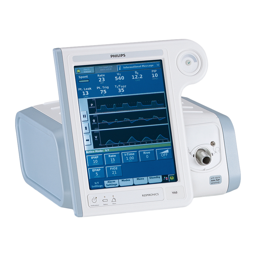
Page 35: About The Graphical User Interface
Compressed waveforms window with Alarms/ Messages list (see page 8-2) Window/window tabs (see page 6-1) Power symbols Help button (see page 5-2) (see page 6-22) Figure 3-7: Parts of graphical user interface 3-11 1047358 Rev N Respironics V60 Ventilator User Manual... -
Page 36: Navigating The Graphical User Interface
The navigation ring also lets you adjust the position of the cursor in the waveforms window while the screen is frozen. See Freezing and unfreezing waveforms on page 7-3 for more information. 3-12 Respironics V60 Ventilator User Manual 1047358 Rev N... -
Page 37: Starting Up The Ventilator
ON/Shutdown key, then the Accept button on the navigation ring. Training Product training is available. Contact your local Philips sales representative or Philips Customer Support for assistance. Call 1-800-225-0230 for ordering and 1-800-722-9377 for service. - Page 38 Chapter 3 General information (This page is intentionally blank.) 3-14 Respironics V60 Ventilator User Manual 1047358 Rev N...
- Page 39 Chapter 4. Principles of operation System operational The Respironics V60 Ventilator is a microprocessor-controlled pneumatic system that delivers a mixture of air and oxygen. It is powered by AC with overview optional battery backup to protect against power failure or unstable power and to facilitate intrahospital transport.
-
Page 40: Principles Of Operation
Triggering, cycling, and leak adaptation Unlike other ventilators, the Respironics V60 Ventilator does not require you to set triggering and cycling sensitivity or to adjust baseline flow.The ventilator’s unique Auto-Trak Sensitivity algorithm adjusts these automatically; see “Auto- Trak Sensitivity”... -
Page 41: Pressure Rise Time
Auto-Trak Sensitivity An important characteristic of the Respironics V60 Ventilator is its ability to recognize and compensate for intentional and unintentional leaks in the system, and to automatically adjust its triggering and cycling algorithms to maintain optimum performance in the presence of leaks. - Page 42 (SET); see Figure 4-3. The SET represents the intersection of the flow waveform and a line of a given slope. SET is updated each breath. Spontaneous exhalation threshold Figure 4-3: Spontaneous exhalation threshold (SET) Respironics V60 Ventilator User Manual 1047358 Rev N...
-
Page 43: Leak Adaptation
Figure 4-4 shows how the ventilator adjusts the baseline. Inspiration Cycle to Flow exhalation baseline Original End exhalation baseline Additional leak TIME Spontaneous trigger Patient flow Adjustment of baseline Figure 4-4: Expiratory flow adjustment 1047358 Rev N Respironics V60 Ventilator User Manual... -
Page 44: Auto-Trak+ (Optional)
Volume adjustment Figure 4-5: Tidal volume adjustment Auto-Trak+ (optional) The Auto-Trak+ option for the Respironics V60 Ventilator lets you further adjust the level of Auto-Trak Sensitivity, a feature that recognizes and compensates for intentional and unintentional leaks. This algorithm has multiple breath trigger and cycle thresholds. -
Page 45: Ventilation Modes
Chapter 4 Principles of operation Ventilation modes The Respironics V60 Ventilator operates in the following ventilation modes: • CPAP (continuous positive airway pressure) mode • S/T (spontaneous/timed) mode • PCV (pressure-controlled ventilation) mode • AVAPS (average volume-assured pressure support) mode (optional) •... -
Page 46: Cpap Mode
– a time when patients may be uncomfortable with CPAP – and returning it to the set CPAP level before the end of exhalation. Figure 4-6: CPAP controls CPAP Time Figure 4-7: CPAP waveforms Respironics V60 Ventilator User Manual 1047358 Rev N... -
Page 47: Pcv Mode
Figure 4-9 shows a PCV mode pressure waveform. Figure 4-8: PCV controls Pressure Rise IPAP EPAP Time Patient-triggered I-Time Machine-triggered (Spont) breath (Timed) breath 1/Rate Figure 4-9: PCV pressure waveform 1047358 Rev N Respironics V60 Ventilator User Manual... -
Page 48: S/T Mode
S/T mode are shown in Figure 4-10. Figure 4-11 shows an S/T mode pressure waveform. Figure 4-10: S/T controls Pressure Mandatory Rise (Timed) breath IPAP EPAP Time Patient-triggered (Spont) 1/Rate spontaneous breath with I-Time pressure support Figure 4-11: S/T pressure waveform 4-10 Respironics V60 Ventilator User Manual 1047358 Rev N... -
Page 49: Avaps Mode (Optional)
EPAP + (target volume / 60 ml/cmH • EPAP + 8 cmH • Pmin The control settings active in the AVAPS mode are shown in Figure 4-12. Figure 4-13 shows AVAPS mode waveforms. Figure 4-12: AVAPS controls 4-11 1047358 Rev N Respironics V60 Ventilator User Manual... - Page 50 Chapter 4 Principles of operation Max P Mandatory (Timed) Rise breath Min P EPAP I-Time Patient-triggered (Spont) 1/Rate spontaneous breath Time Figure 4-13: AVAPS waveforms 4-12 Respironics V60 Ventilator User Manual 1047358 Rev N...
-
Page 51: Ppv Mode (Optional)
PPV. You adjust assist levels to optimize patient comfort. The resultant pressure support delivered in the PPV mode is the resistance assist times patient flow plus the elastance assist times the patient volume. The end 4-13 1047358 Rev N Respironics V60 Ventilator User Manual... - Page 52 “About Max V and Max P alarms and alarm limits” on page 6-7. 1 Marantz, S., Patrick, W., Webster, K., et al. “Response of ventilator-dependent patients to different levels of proportional assist.” Journal of Applied Physiology, Vol. 80: 397-403, 1996. 4-14 Respironics V60 Ventilator User Manual 1047358 Rev N...
- Page 53 Chapter 4 Principles of operation Max V Increase in patient demand Time Max P EPAP Figure 4-15: PPV waveforms 4-15 1047358 Rev N Respironics V60 Ventilator User Manual...
-
Page 54: Oxygen Mixing
Assumptions: At an O setting of 100% and an oxygen supply with a 50 psig inlet pressure capable of delivering up to160 L/min. Figure 4-16: O concentration as a function of total ventilator flow 4-16 Respironics V60 Ventilator User Manual 1047358 Rev N... -
Page 55: Setting Up The Ventilator For Use
Consult Table 10-9 on page 10-6 for appropriate oxygen pressure ranges. Installing an oxygen Install a Teledyne MX300 oxygen monitor, or the equivalent, and follow the manufacturer’s instructions for setup and calibration. monitor 1047358 Rev N Respironics V60 Ventilator User Manual... -
Page 56: Connecting To Ac Power
WARNING: To prevent unintentional disconnection of the power cord, always use the correct, Philips-supplied power cord and lock it into place with the power cord retainer before you switch the ventilator on. The retainer is designed to hold the connector end of the Philips-supplied cord securely in place. -
Page 57: Installing The Patient Circuit
Install the patient circuit as shown in this section. For a list of compatible parts and accessories offered by Philips, see “Parts and accessories” on page C-1. Assemble the patient circuit, including the main flow (inspiratory) bacteria filter, proximal pressure line, oxygen sensor tee, and if desired, humidifier and nebulizer. - Page 58 Figure 5-1: Noninvasive patient circuit, without humidification Proximal pressure port Ventilator outlet Oxygen sensor tee Bacteria filter Proximal filter Proximal pressure line Water trap Humidifier Figure 5-2: Invasive patient circuit, with humidification Respironics V60 Ventilator User Manual 1047358 Rev N...
-
Page 59: Connecting External Devices
Connect the ventilator to a remote alarm (nurse call) device and a patient monitor or other external device, if applicable. devices The Respironics V60 Ventilator can communicate with a Philips patient monitor using the IntelliBridge Open Interface. See “Using Philips monitors and the IntelliBridge Open Interface” on page B-13. The ventilator also supports the VueLink Open Interface. -
Page 60: Running Alarm Tests
2. VERIFY that the High Inspiratory Pressure alarm is activated, the ventilator cycles into exhalation, and pressure falls to 6 cmH O (the EPAP level). 3. Raise the HIP alarm limit to 15 cmH Respironics V60 Ventilator User Manual 1047358 Rev N... -
Page 61: Low Tidal Volume
1. Disconnect the patient circuit (including bacteria filter) from the ventilator outlet, and block the ventilator outlet. 2. VERIFY that the Patient Circuit Occluded alarm is activated. 3. Unblock the outlet, and reconnect the circuit. 4. VERIFY that the alarm resets. 1047358 Rev N Respironics V60 Ventilator User Manual... -
Page 62: Using The Ventilator For Intra-Hospital Transport
Avoid using masks that have an exhalation port built into the mask when there is already an exhalation port in the circuit. • Be aware that oxygen is more rapidly depleted at higher leak rates (see Figure 5-3). Respironics V60 Ventilator User Manual 1047358 Rev N... - Page 63 Leak of 50 L/min b. V = 500 mL, Rate = 20 BPM, EPAP = 6 cmH O, IPAP = 18 cmH Figure 5-3: Duration of cylinder oxygen (13,790 kPa/2000 psig) at various leak rates 1047358 Rev N Respironics V60 Ventilator User Manual...
-
Page 64: Storing The Ventilator Between Patient Use
Chapter 5 Setting up the ventilator for use Storing the ventilator See “Storage between patient use” on page 9-7 for information about storing the ventilator. between patient use 5-10 Respironics V60 Ventilator User Manual 1047358 Rev N... -
Page 65: Operation
5-5. Access the ventilator setting windows from the tabs at the bottom of the screen. page 6-3 page 6-12 page 6-2 page 6-17 page 6-20 page 6-22 1047358 Rev N Respironics V60 Ventilator User Manual... -
Page 66: Changing The Mode
2. Select the desired mode. Active mode 3. Adjust settings as desired (see “Changing individual ventilator settings” on page 6-4). Newly adjusted setting values are shown in yellow. 4. Select Activate Mode to apply. Respironics V60 Ventilator User Manual 1047358 Rev N... -
Page 67: Changing Control Settings
2. Select the active mode. Active mode 3. Adjust settings as desired (see “Changing individual ventilator settings” on page 6-4). Newly adjusted setting values are shown in yellow. 4. Select Activate Batch Change to apply. 1047358 Rev N Respironics V60 Ventilator User Manual... -
Page 68: Changing Individual Ventilator Settings
2. Select the desired setting. As an example we will show the IPAP adjustment. 3. The setting window opens. Adjust the setting. Select Accept to apply. Adjustment Setting range scale arrow button Additional information Current settings area Proposed value Respironics V60 Ventilator User Manual 1047358 Rev N... -
Page 69: Using The Ramp Time Function
100% oxygen to the patient. It is available during Screen Lock status. Follow these instructions to use the 100% O function: 1. Select the 100% O2 button in the main GUI window. 1047358 Rev N Respironics V60 Ventilator User Manual... - Page 70 2. The ventilator delivers 100% oxygen for two minutes. A countdown timer displays. While 100% oxygen delivery is active, you can press the +2:00 button to add two minutes more. Press Cancel to stop. Respironics V60 Ventilator User Manual 1047358 Rev N...
-
Page 71: Using Ppv
When the Max V (PPV maximum volume limit) is reached, the breath is terminated and a message is displayed. After the limit is reached in three consecutive breaths, the audible alarm sounds. A PPV waveform with Max V is shown in Figure 6-1. 1047358 Rev N Respironics V60 Ventilator User Manual... - Page 72 (estimated exhaled tidal volume) measurement may remain below the set Max V limit even though the inspired volume exceeds Max V. This results from variable leakage, which reduces the exhaled volume in relation to the inspired volume. Respironics V60 Ventilator User Manual 1047358 Rev N...
-
Page 73: Guidelines For Using Ppv
Focus on Max E. Maintaining sufficient volume is typically the emphasis, not overcoming increased resistance. • Mixed disease processes affecting both resistance and elastance: Titrate both Max R and Max E settings. 1047358 Rev N Respironics V60 Ventilator User Manual... - Page 74 3. Repeat the process above adjusting Max R, increasing and decreasing in increments of 1 cmH O/L/s to optimize patient comfort. 4. Repeat adjustment for Max E as needed. 5. Adjust PPV % downward as tolerated. 6-10 Respironics V60 Ventilator User Manual 1047358 Rev N...
- Page 75 Repeat Max E titration as needed Increase Max E by 2 cmH Titrate PPV % downward as tolerated Reduce Max E by 2 cmH O/L for patient comfort Figure 6-3: PPV initial setup 6-11 1047358 Rev N Respironics V60 Ventilator User Manual...
-
Page 76: Changing Alarm Settings
2. Select the desired setting, adjust it, and select Accept to apply. The ventilator annunciates an alarm when a monitored value goes out of the range bounded by the alarm limits. 6-12 Respironics V60 Ventilator User Manual 1047358 Rev N... -
Page 77: Selecting The Mask And Exhalation Port
Accept to apply. For information concerning mask/port leak characteristics, see the instructions provided with each mask/port. See Appendix C for a list of masks, circuits, and related components used with the ventilator. 6-13 1047358 Rev N Respironics V60 Ventilator User Manual... - Page 78 ET/Trach ET or tracheostomy tube Leak 1 Mask with minimal intentional leak characteristics. Enter Leak 1 for any of these Philips Respironics masks: • Contour Deluxe nasal mask • PerformaTrak mask • Image3 full face mask • AF421, AF531 (EE) Leak 2 Mask with medium intentional leak characteristics.
- Page 79 Philips Respironics Disposable Exhalation Port Whisper Swivel Philips Respironics Whisper Swivel Philips Respironics Plateau Exhalation Valve Other Exhalation port not supplied by Philips Respironics. None No inline circuit exhalation port NOTE: If you select None, refer to the manufacturer’s instructions to make sure the mask selected contains an exhalation port.
-
Page 80: Running The Exhalation Port Test
1. Disconnect the patient circuit from the mask/patient interface. 2. Occlude the circuit outlet. Select Start Test. 3. Wait while the test runs. Progress 4. Verify that Test Passed is displayed. 6-16 Respironics V60 Ventilator User Manual 1047358 Rev N... -
Page 81: Troubleshooting
The Alarm Volume Escalation status is also displayed on this screen. See “Alarm Volume Escalation” on page E-11 for more information. Mask/Port See “Selecting the mask and exhalation port” on page 6-13. 6-17 1047358 Rev N Respironics V60 Ventilator User Manual... -
Page 82: Vent Info (Ventilator Information)
Changing Auto-Trak+ settings 1. Select Auto-Trak+ from the Menu window. 6-18 Respironics V60 Ventilator User Manual 1047358 Rev N... - Page 83 When Auto-Trak+ is active (when either Trigger or E-Cycle is set to a value other than Normal), the ventilator setting window displays Auto-Trak+. Auto-Trak+ active Additionally, after power-on the Messages list displays the Auto-Trak+ settings for 5 minutes. 6-19 1047358 Rev N Respironics V60 Ventilator User Manual...
-
Page 84: Standby
The standby mode request cancels in 60 seconds if the patient remains connected. NOTE: Standby mode disables alarms and should be used when the patient is disconnected. 6-20 Respironics V60 Ventilator User Manual 1047358 Rev N... - Page 85 3. To resume ventilation, reconnect the patient. When the ventilator senses a patient breathing effort, ventilation automatically resumes in the previous mode. NOTE: You can also manually resume ventilation with the Restart Mode button. 6-21 1047358 Rev N Respironics V60 Ventilator User Manual...
-
Page 86: Help Function
Chapter 6 Operation Help function Select the help button to display additional information. Help messages are displayed: Help message 6-22 Respironics V60 Ventilator User Manual 1047358 Rev N... -
Page 87: Table Of Modes And Control Settings
4 to 40 cmH application and maintenance of pressure above atmospheric at the airway throughout the inspiration phase of positive-pressure mechanical ventilation. EPAP IPAP Must be greater than or equal to EPAP 6-23 1047358 Rev N Respironics V60 Ventilator User Manual... - Page 88 Delivery of excessive pressure or volume can occur from a sudden increase in mask leak, inappropriate settings, or a plugged or kinked proximal pressure line. Conversely, insufficient treatment may result if limits are set too low. 6-24 Respironics V60 Ventilator User Manual 1047358 Rev N...
- Page 89 (target) pressure. fastest) If the Rise Time is insufficient to reach the target IPAP pressure, adjust the Rise Time or I-Time setting. Proposed rise slope in relation to EPAP and IPAP 6-25 1047358 Rev N Respironics V60 Ventilator User Manual...
- Page 90 It will also alert the clinician to pressure degradation due to excessive leaks. See figure below. alarm IPAP alarm EPAP 6-26 Respironics V60 Ventilator User Manual 1047358 Rev N...
- Page 91 The interval from the 5 to 60 secs Pressure Delay Time) detection of low inspiratory pressure until the alarm becomes active. • (Low Minute Low expiratory minute OFF to 99.0 L/min Ventilation Alarm) volume. 6-27 1047358 Rev N Respironics V60 Ventilator User Manual...
- Page 92 Chapter 6 Operation (This page is intentionally blank.) 6-28 Respironics V60 Ventilator User Manual 1047358 Rev N...
-
Page 93: Patient Monitoring
The following symbols may be displayed in place of numeric values: Data is not valid, and/or ventilator is in standby mode or disconnected +++ Data is over range - - - Data is under range 1047358 Rev N Respironics V60 Ventilator User Manual... -
Page 94: Table Of Monitored Parameters
The vertical scale button autoscales the Y axes to best fit the current data. The horizontal (time adjust) button rescales the X axis to show 3, 6, 12, or 24 seconds. Respironics V60 Ventilator User Manual 1047358 Rev N... -
Page 95: Freezing And Unfreezing Waveforms
Data values at cursor location for pressure, flow, and volume are displayed in the white boxes. Unfreeze the waveforms with the resume button. Resume button unfreezes waveforms Measurements at cursor Cursor Figure 7-2: Waveform window with frozen screen 1047358 Rev N Respironics V60 Ventilator User Manual... - Page 96 Chapter 7 Patient monitoring (This page is intentionally blank.) Respironics V60 Ventilator User Manual 1047358 Rev N...
- Page 97 You may silence the alarm if possible. 2. Correct the alarm condition, referring to the alarm messages in Table 8-2. You can modify alarm settings at any time through the Alarm Settings tab. 1047358 Rev N Respironics V60 Ventilator User Manual...
-
Page 98: Alarms And Messages
Alarms/Messages list (compressed) Up to 7 entries, prioritized from high to low and with any informational messages Active mode/ on the bottom feature bar Alarm LED Active alarms Figure 8-1: Visual alarm indications Respironics V60 Ventilator User Manual 1047358 Rev N... - Page 99 Table 8-4. Loss of Blank Blank Immediately secure alter- power native ventilation for the patient. * The volume of the primary alarm is the same for low- and high-priority alarms. 1047358 Rev N Respironics V60 Ventilator User Manual...
-
Page 100: Setting Alarm Loudness
Chapter 8 Alarms and messages Figure 8-2: Vent Inoperative screen Setting alarm You can set the alarm loudness from the Menu window (see “Loudness” on page 6-17). loudness Respironics V60 Ventilator User Manual 1047358 Rev N... -
Page 101: Silencing Alarms
If the alarm cannot be manually reset, you see the following: Clearing autoreset alarms from the Alarms list Autoreset alarms are shown with text crossed out in the Alarms list. Clear the message from the Alarms list by selecting Alarm Reset. 1047358 Rev N Respironics V60 Ventilator User Manual... -
Page 102: Hiding/Displaying Alarm Messages
Check the patient. If prob- High sure than 92 psig, so O enrich- lem persists, provide alter- (49) ment ends. Autoresets native ventilation. Have when O supply pressure ventilator serviced. falls below 87 psig. Respironics V60 Ventilator User Manual 1047358 Rev N... - Page 103 (53) setting. Escalates to a high- are appropriate. If problem priority alarm if the alarm persists, provide alternative condition persists for more ventilation. Have ventilator than 60 sec. serviced. 1047358 Rev N Respironics V60 Ventilator User Manual...
- Page 104 If or oxygen flow sensor cali- problem persists, provide al- bration failed, or oxygen in- ternative ventilation. Have let pressure sensor ventilator serviced. calibration failed. The ven- tilator discontinues oxygen support. Respironics V60 Ventilator User Manual 1047358 Rev N...
- Page 105 Max E, or Max R setting. Tar- get pressure is limited. At first, an information message. If condition per- sists for three consecutive PPV inspirations, this esca- lates to a high-priority alarm. 1047358 Rev N Respironics V60 Ventilator User Manual...
- Page 106 (58) values were restored by the user. Vent Inoperative x See Table 8-4 on page 8-15 description of failure 8-10 Respironics V60 Ventilator User Manual 1047358 Rev N...
- Page 107 Check the patient. Provide High ter Calibration Data sure of 686.0 mmHg (ap- alternative ventilation. Have (18) Error proximately 900 m/2953 ft the ventilator serviced. above sea level) used in cal- culations 8-11 1047358 Rev N Respironics V60 Ventilator User Manual...
- Page 108 PCBA ADC alternative ventilation. Have (27) Failed the ventilator serviced. Check Vent: Flash Technical failure Check the patient. Provide High File System Error alternative ventilation. Have (37) the ventilator serviced. 8-12 Respironics V60 Ventilator User Manual 1047358 Rev N...
- Page 109 Data Error the ventilator serviced. Check Vent: O Sup- Continues to ventilate with Check the patient. Provide High ply Pressure Sensor air only alternative ventilation. Have (17) Range Error the ventilator serviced. 8-13 1047358 Rev N Respironics V60 Ventilator User Manual...
- Page 110 Have (12) Range Error alarms are compromised. the ventilator serviced. Check Vent: Ventila- Technical failure Check the patient. Provide High (3) tor Restarted alternative ventilation. Have the ventilator serviced. 8-14 Respironics V60 Ventilator User Manual 1047358 Rev N...
- Page 111 Technical failure. The venti- Check the patient. Provide al- High 1008 lator is in the ventilator inop- ternative ventilation. Have the (10) erative state. ventilator serviced. Machine and Proximal Pres- sure Sensors Failed 8-15 1047358 Rev N Respironics V60 Ventilator User Manual...
- Page 112 Vent Inoperative Technical failure. The venti- Check the patient. Provide al- High 100B lator is in the ventilator inop- ternative ventilation. Have the (13) erative state. ventilator serviced. Watchdog Test Failed 8-16 Respironics V60 Ventilator User Manual 1047358 Rev N...
- Page 113 1. Reprocessing Medical Devices in Health Care Settings: Validation Methods and Labeling Guidance for Industry and Food and Drug Administration Staff, 2015. Food and Drug Administration (FDA) 1047358 Rev N Respironics V60 Ventilator User Manual...
-
Page 114: Care And Maintenance
CAUTION: Do not attempt to sterilize or autoclave the ventilator. NOTE: Use of unapproved cleaning and disinfecting agents may cause damage to the enclosure, touchscreen, or parts of the ventilator. Respironics V60 Ventilator User Manual 1047358 Rev N... -
Page 115: Approved Disinfecting Agents
4. Rinse with a clean cloth dampened with water and allow to dry completely before reuse. Bacteria filter, patient Follow the manufacturer’s instructions that accompany the accessory. circuit, and other accessories 1047358 Rev N Respironics V60 Ventilator User Manual... -
Page 116: Preventive Maintenance
To ensure proper system performance, use a Respironics-approved air inlet filter. Perform preventive maintenance on your Respironics V60 Ventilator according to the schedule in Table 9-2. You can view the hours of ventilator operation in the Vent Info window (“Vent Info (ventilator information)” on page 6-18). The following subsections provide details for some of these preventive maintenance procedures. -
Page 117: Replacing The Air Inlet Filter
4. Install a new air filter by tucking it into the recessed area. Replace the side panel, and push in and turn the D-ring fastener one-quarter turn until it locks. Captive fastener Bracket Air inlet filter Figure 9-1: Replacing the air inlet filter 1047358 Rev N Respironics V60 Ventilator User Manual... -
Page 118: Cleaning Or Replacing The Cooling Fan Filter
4. Replace the filter, then snap the filter cover into place. Fan retaining pin (Do not remove) Filter cover Fan (Do not remove) Foam filter Figure 9-2: Replacing the cooling fan filter Respironics V60 Ventilator User Manual 1047358 Rev N... -
Page 119: Removing And Replacing The Battery
Service and Repairs For technical service or repair information not included in this chapter, contact Philips. A Respironics V60 Ventilator Service Manual is available, PN 1049766. The Service Manual includes removal and installation procedures, parts lists, and testing and troubleshooting information. -
Page 120: Repacking And Shipping
Remove the battery from the ventilator before shipping the ventilator. See “Installing the optional battery” on page A-3 for more information. Ship the battery and ventilator separately in appropriate packaging in conformance with federal, state, and local regulations. Respironics V60 Ventilator User Manual 1047358 Rev N... -
Page 121: Technical Specifications
PPV % 0 to 100% Ramp Time OFF, 5 to 45 min 5 min ± 1 sec Rate (Respiratory Rate) 4 to 60 BPM 1 BPM ± 1 BPM 4 BPM 10-1 1047358 Rev N Respironics V60 Ventilator User Manual... - Page 122 Factory default Rise (Rise Time) 1 to 5 (AVAPS Target Tidal 200 to 2000 mL BTPS 5 mL ± 15% 500 mL Volume) Table 10-2: Controls active in Respironics V60 ventilation modes CPAP AVAPS Timing Rate Rate I-Time I-Time* Baseline pressure...
-
Page 123: Patient Data
P waveform 0 to 50 cmH Time axis: 1 second waveform -240 to 240 L/min BTPS Time axis: 1 second V waveform 0 to 3500 mL BTPS Time axis: 1 second 10-3 1047358 Rev N Respironics V60 Ventilator User Manual... -
Page 124: Alarms
1 to 10 Mask/ET Selection ET/Trach, 1, 2, 3, 4, Other Exhalation Port Selection DEP (Philips Respironics Disposable Exhalation Port, Whisper Swivel (Philips Respironics Whisper Swivel), PEV (Philips Respironics Plateau Exhalation Valve, Other (Other Exhalation Port), None (No inline circuit... -
Page 125: Diagnostic Mode Functions
Weight: 36.1 kg (79.5 lb) Width: 64 cm (25 in) Height: 136* cm (53.5* in) to top of ventilator *Does NOT include height of flexible circuit arm 10-5 1047358 Rev N Respironics V60 Ventilator User Manual... -
Page 126: Environmental Specifications
Pressure: 3.66 to 6.00 bar / 366 to 600 kPa / 53 to 87 psig Flow: 175 SLPM Air supply Integrated blower Inspiratory outlet Connector: ISO 15 mm female/22 mm male conical (to patient port) 10-6 Respironics V60 Ventilator User Manual 1047358 Rev N... -
Page 127: Electrical Specifications
Flow range -240 to 240 L/min BTPS Pressure range 4 to 40 cmH Dynamic pressure regulation ± (2 cmH O + 4% of target) NOTE: Negative (subatmospheric) pressure settings are not available. 10-7 1047358 Rev N Respironics V60 Ventilator User Manual... - Page 128 Average sound power level is approx. 54 dB(A) mea- sured at the ventilator Average sound pressure level is approx. 46 dB(A) mea- sured 1 meter from the ventilator * In accordance with 3rd Edition testing methods 10-8 Respironics V60 Ventilator User Manual 1047358 Rev N...
- Page 129 Inspect the front panel for inspection scratches or abrasions. Correct and/or report any problems found to Philips before using the ventilator. Before using the ventilator the first time, we recommend wiping the exterior clean and disinfecting components according to the instructions in Chapter 9.
-
Page 130: First-Time Installation
Use the brakes to lock and unlock the wheels as needed. Make sure the wheels are unlocked before moving the ventilator. Power cords can be stored on stand hooks Wheel lock Figure A-1: Respironics V60 Ventilator on stand Respironics V60 Ventilator User Manual 1047358 Rev N... -
Page 131: Installing The Optional Battery
3. Using a 3-mm hex wrench, remove the battery bracket by removing two screws. 4. Holding the battery so that the vent hole faces up and the Philips logo faces out, thread the battery cable through the battery bracket. Position and place the battery inside the battery compartment. - Page 132 Following battery installation, if a Check Vent or Vent Inoperative alarm occurs when verifying ventilator operation, discontinue use of the ventilator immediately and contact Philips. The Vent Inoperative alarm occurs if AC power is disconnected and a battery is not installed, or if the battery is fully discharged.
- Page 133 Appendix A First-time installation Captive fastener Bracket Battery Orient with vent hole on top and Philips logo facing out Battery cable Figure A-2: Installing the battery 1047358 Rev N Respironics V60 Ventilator User Manual...
-
Page 134: Installing Oxygen Inlet Connector And Ac Power Cord
Appendix A First-time installation Installing oxygen Respironics V60 Ventilators destined for Japan, China and the U.S. are pre- configured. V60 Ventilators shipped to other countries may require installation inlet connector and of the power cord and oxygen inlet connector. AC power cord 1. - Page 135 WARNING: To prevent unintentional disconnection of the power cord, always use the correct, Philips-supplied power cord and lock it into place with the power cord retainer before you switch the ventilator on. The retainer is designed to hold the connector end of the Philips-supplied cord securely in place.
-
Page 136: Installing The Oxygen Manifold Kit
After completing the setup activities described in Chapter 5, set or check the ventilator settings for language, units of measure, and time in the diagnostic screen calibration mode (see Appendix E). Calibrate the screen as required, referring to Appendix E Respironics V60 Ventilator User Manual 1047358 Rev N... -
Page 137: Communications Interface
Also be aware that local laws may take priority over the above mentioned requirements. If in doubt, consult Philips. WARNING: The USB port is not currently available for use. DO NOT connect or attempt to power any equipment from the USB port. -
Page 138: Serial And Analog I/O Port
This port permits the ventilator to send data to a patient monitor or a hospital information system. The ventilator is compatible with Philips monitors (see “Using Philips IntelliBridge or VueLink” on page B-13), It is compatible with Cardiopulmonary Corporation’s Bernoulli Ventilator Management System. For complete compatibility information, contact your Philips representative. - Page 139 Output HIS analog output #2 (0 IN01 to 5 V) OUT2 to 5 V) HIS_SIG_RTN Power HIS RS232/Signal Chassis Power Cable shield common Figure B-2: RS-232 serial and analog I/O connector pinout 1047358 Rev N Respironics V60 Ventilator User Manual...
-
Page 140: Communications Protocol
The ventilator stores and responds to valid commands in the order received. It returns invalid commands in an error message. The ventilator also supports service-oriented commands. Contact Philips for details. In the tables shown, a space is designated as "◆... - Page 141 NPPV low inspiratory 3◆◆◆◆◆ 0 to 40 Off = 0 pressure alarm limit setting ◆◆◆◆◆◆ Unused Always output as "◆◆◆◆◆◆" NPPV low tidal volume 0◆◆◆◆◆ 0 to 1500 Off = 0 alarm limit setting 1047358 Rev N Respironics V60 Ventilator User Manual...
- Page 142 Measured percent of 20◆◆◆◆ 0 to 100 "◆◆◆◆◆◆" in breaths triggered by the standby mode or patient during exhalation port leak test ◆◆◆◆◆◆ Unused Always output as "◆◆◆◆◆◆" Respironics V60 Ventilator User Manual 1047358 Rev N...
- Page 143 Occlusion alarm status NORMAL NORMAL ALARM◆ RESET◆ Safety valve status NORMAL NORMAL ALARM◆ RESET◆ Low internal battery NORMAL NORMAL alarm status ALARM◆ RESET◆ Nonvolatile memory NORMAL NORMAL failure—Using default ALARM◆ settings RESET◆ 1047358 Rev N Respironics V60 Ventilator User Manual...
- Page 144 Always output as "◆◆◆◆◆◆" Low tidal volume alarm NORMAL NORMAL status ALARM◆ RESET◆ Low spontaneous tidal NORMAL NORMAL Low Tidal Volume volume alarm status Alarm status ALARM◆ RESET◆ ◆◆◆◆◆◆ Unused Always output as "◆◆◆◆◆◆" Respironics V60 Ventilator User Manual 1047358 Rev N...
- Page 145 Always output as "◆◆◆◆◆◆" Alarm silence status OFF◆◆◆ ON◆◆◆◆ OFF◆◆◆ Screen lock status OFF◆◆◆ ON◆◆◆◆ OFF◆◆◆ ◆◆◆◆◆◆ 131 to Unused Always output as "◆◆◆◆◆◆" Stop code 0x03 ASCII End Transmission character (ETX) 1047358 Rev N Respironics V60 Ventilator User Manual...
- Page 146 21 to 100 setting ◆◆◆◆◆◆ Unused Always output as "◆◆◆◆◆◆" PEEP or EPAP setting 0.0◆◆◆ 4.0 to 25.0 CPAP or EPAP setting ◆◆◆◆◆◆ 12 to 21 Unused Always output as "◆◆◆◆◆◆" B-10 Respironics V60 Ventilator User Manual 1047358 Rev N...
- Page 147 0.01 0.00 to 1.50 Lo V alarm setting tidal volume alarm setting Low exhaled minute 0.0◆◆◆ 0.0 to 99.0 volume alarm setting High respiratory rate 0◆◆◆◆◆ 5 to 90 alarm setting B-11 1047358 Rev N Respironics V60 Ventilator User Manual...
- Page 148 Inhalation time setting 0.10◆◆◆ 0.01 0.10 to 3.00 I-Time in PCV mode "◆◆◆◆◆◆" in other modes ◆◆◆◆◆◆ 83 to 88 Unused Always output as "◆◆◆◆◆◆” Alarm silence status ON◆◆◆◆ ON◆◆◆◆ OFF◆◆◆ B-12 Respironics V60 Ventilator User Manual 1047358 Rev N...
-
Page 149: Using Philips Intellibridge Or Vuelink
Decisions for patient care should not be based solely on the data obtained through the IntelliBridge system. The Respironics V60 Ventilator can communicate with a Philips patient monitor using the IntelliBridge Open Interface. Figure B-3 shows the required hardware setup. The IntelliBridge Open Interface requires a ventilator baud rate 19,200. -
Page 150: Using Philips Monitors And The Vuelink Open Interface
Data Display The data from your Respironics V60 Ventilator is displayed in several windows on your Philips monitor. This data may be labeled differently on the monitor than on the ventilator. Refer to Table B-3 to interpret these labels. - Page 151 Appendix B Communications interface Table B-3: Ventilator data displayed on Philips monitor (continued) Monitor label Ventilator label Monitored parameters awRR Rate MV or MINVOL PIP or Ppeak PtLeak Pt. Leak PtTrig Pt. Trigger Tin/Tt Not shown Tot.Leak Modes Same as ventilator mode name...
- Page 152 Appendix B Communications interface Table B-3: Ventilator data displayed on Philips monitor (continued) Monitor label Ventilator label Alarm messages HIGH INSP PRESS High Inspiratory Pressure HIGH O2 SUPPLY High O Supply Pressure HIGH RESP RATE High Rate HIGH EXH TV...
-
Page 153: Remote Alarm Port
Use on Normally Opened nurse call systems (system expects to 1003742 alarm state = closed see closed contacts when ventilator alarms). For ¼” jack. Remote alarm cable kit Philips Respironics (LifeCare) 1003743 B-17 1047358 Rev N Respironics V60 Ventilator User Manual... - Page 154 Appendix B Communications interface (This page is intentionally blank.) B-18 Respironics V60 Ventilator User Manual 1047358 Rev N...
-
Page 155: Parts And Accessories
This appendix lists parts and accessories supplied by Philips that are compatible with the Respironics V60 Ventilator. Contact your Philips representative to order these parts. Please refer to Philips.com/hrc for a complete list of accessories and part numbers for your ventilator and region. Masks... -
Page 156: Exhalation Ports
† clips Bilevel/CPAP single-limb heated circuit, with extension and 1020524 989805610851 Philips Respironics disposable exhalation port (DEP) (Fisher & Paykel) Respironics noninvasive circuit with disposable swivel exhalation 1069210 989805634871 port with filter port, proximal pressure line, hanger, and hose clips (main flow and exhalation filters not included) Proximal pressure line, single-use, 2.13 m (7 ft), with a total of 2... -
Page 157: Bacteria Filter
• V60 Ventilator serial numbers beginning with a “2,” all serial numbers greater than and including 201007805 Description Part number Order number Respironics V60 Ventilator stand, partially assembled 1109866 989805648691 Cylinder holder for ventilator stand 1109869 989805648721 1047358 Rev N... - Page 158 IntelliBridge EC5 cable (10 m) 865114-105 NOTE: When using non-Respironics cables, follow the special setup procedure in Chapter 6 of the Respironics V60 Ventilator Service Manual, PN 1049766. Otherwise, the ventilator may not power up correctly. Respironics V60 Ventilator User Manual...
-
Page 159: Regulatory Compliance
2013 safety IEC 60601-1-8; Medical electrical equipment – Part 1-8: General requirements for Ed. 2.1 safety IEC 62366; 2007 + Medical devices - Application of usability engineering to medical A1: 2004 devices 1047358 Rev N Respironics V60 Ventilator User Manual... -
Page 160: Electromagnetic Compatibility Declaration
Harmonic Class A the public low voltage power supply network that emissions supplies buildings used for domestic purposes. IEC 61000-3-2 Voltage Complies fluctuations/flicker emissions IEC 61000-3-3 Respironics V60 Ventilator User Manual 1047358 Rev N... -
Page 161: Electromagnetic Immunity
(50/60 Hz) should be at levels characteristic magnetic field of a typical location in a typical hospital environment. IEC 61000-4-8 NOTE: is the AC mains voltage prior to application of the test level. 1047358 Rev N Respironics V60 Ventilator User Manual... - Page 162 If abnormal performance is observed, additional measures may be necessary, such as re-orienting or relocating the V60 Ventilator. d. Over the frequency range 150 kHz to 80 MHz, field strengths should be less than 3 V/m. Respironics V60 Ventilator User Manual 1047358 Rev N...
- Page 163 NOTE 4: These guidelines may not apply in all situations. Electromagnetic propagation is affected by absorption and reflection from structures, objects and people. 1047358 Rev N Respironics V60 Ventilator User Manual...
-
Page 164: Weee Recycling Directive
Safety - Collateral Standard IEC 60601-2-12 Medical Electrical Equipment – Part 2-12: Particular Requirements for the Safety of Lung Ventilators – Critical Care Ventilators UL 60601-1 Medical Electrical Equipment, Part 1: General Requirements for Safety Respironics V60 Ventilator User Manual 1047358 Rev N... - Page 165 Safety IEC 60601-1-8 Medical Electrical Equipment, Part 1-8: General Requirements for Safety ISO 80601-2-12 Medical Electrical Equipment – Part 2-12: Particular requirements for basic safety and essential performance of critical care ventilators 1047358 Rev N Respironics V60 Ventilator User Manual...
- Page 166 Appendix D Regulatory compliance (This page is intentionally blank.) Respironics V60 Ventilator User Manual 1047358 Rev N...
-
Page 167: Diagnostic Mode
2. Press and hold the Accept button on the navigation ring and turn on the ventilator by pressing the ON/Shutdown key. The screen displays Press again for Diagnostics or wait for Ventilation. 1047358 Rev N Respironics V60 Ventilator User Manual... - Page 168 Appendix E Diagnostic mode 3. Within less than 5 seconds, release and press the Accept button again. The Diagnostics Menu (Figure E-1) is displayed. Figure E-1: Diagnostics Menu 4. Select the desired function. Respironics V60 Ventilator User Manual 1047358 Rev N...
-
Page 169: System Settings
Appendix E Diagnostic mode System settings From the System Settings screen (Figure E-2) you can perform the functions below. Figure E-2: System Settings screen 1047358 Rev N Respironics V60 Ventilator User Manual... -
Page 170: Language
The Language function lets you set the language of software display. 1. From the System Settings screen, select Language to display the Set Language screen (Figure E-3). Figure E-3: Set Language screen 1 Respironics V60 Ventilator User Manual 1047358 Rev N... - Page 171 3. A second Set Language screen is displayed (Figure E-4). Select Ventilator Shutdown to apply the change. The change is effective after you restart the ventilator. Figure E-4: Set Language screen 2 1047358 Rev N Respironics V60 Ventilator User Manual...
-
Page 172: Date/Time
1. From the System Settings screen, select Date/Time to display the Set Date and Time screen (Figure E-5). Figure E-5: Set Date and Time screen 2. Adjust the date and time with the + and - buttons; then Apply. Respironics V60 Ventilator User Manual 1047358 Rev N... -
Page 173: Pressure Units
Set Pressure Units screen (Figure E-6). Figure E-6: Set Pressure Units screen 2. The active pressure unit is shown in white type. Select the desired pressure unit. The change is effective after you restart the ventilator. 1047358 Rev N Respironics V60 Ventilator User Manual... -
Page 174: Restore Default Settings
The factory defaults are listed in Chapter 10. 1. From the System Settings screen, select Restore Default Settings to display the Restore Default Settings screen (Figure E-7). Figure E-7: Restore Default Settings screen 2. Select Restore Defaults. Respironics V60 Ventilator User Manual 1047358 Rev N... -
Page 175: Software Options
4. Verify that the options are enabled by selecting Back to System Settings, then Back to Diagnostics Menu, then Service. The Vent Info window should show the new options. 5. Attach the option label as shown in Figure 3-5 on page 3-8. 1047358 Rev N Respironics V60 Ventilator User Manual... -
Page 176: Baud Rate
Baud Rate for Serial Communications screen (Figure E-9). Figure E-9: Set Baud Rate for Serial Communications screen 2. The active baud rate is shown in white type. Select the desired baud rate. E-10 Respironics V60 Ventilator User Manual 1047358 Rev N... -
Page 177: Alarm Volume Escalation
Enabled, you will see a selectable Disable button. Press the button to change the setting. 3. The new setting is applied after the V60 Ventilator is shut down and powered on again. 1. Available in Revision 2.30 software and above. E-11 1047358 Rev N Respironics V60 Ventilator User Manual... -
Page 178: Service
The time, date, and an identifier for event classification are included. 1. From the Service screen, select the Misc tab. 2. The Miscellaneous screen opens (Figure E-11). Select Significant Event Log. Figure E-11: Miscellaneous screen E-12 Respironics V60 Ventilator User Manual 1047358 Rev N... - Page 179 Appendix E Diagnostic mode 3. The Significant Event Log opens (Figure E-12). Use the buttons on right side to navigate through the log. Figure E-12: Significant Event Log screen E-13 1047358 Rev N Respironics V60 Ventilator User Manual...
-
Page 180: Touchscreen Calibration
2. Follow the steps shown. Press on the middle of each target with a blunt, narrow object. If the calibration is not successful, have the ventilator serviced. Exiting the diagnostic Exit the diagnostic mode by turning off ventilator power with the ON/Shutdown key. mode E-14 Respironics V60 Ventilator User Manual 1047358 Rev N... - Page 181 CPAP Continuous positive airway pressure. A ventilation mode that provides a single, continuous level of positive pressure to the patient and a control setting in that mode. Cycle To end inspiration. dB(A) Decibel, a unit of acoustic power. Glossary-1 1047358 Rev N Respironics V60 Ventilator User Manual...
- Page 182 Hectopascal, a unit of pressure measurement. 1 hPa is equal to 1 mbar, which is approximately equal to 1 cmH ID Inner diameter. IEC International Electrotechnical Commission. I:E ratio Ratio of inspiratory to expiratory time. Inop Inoperative. Inspiration:exhalation ratio See I:E ratio. Glossary-2 Respironics V60 Ventilator User Manual 1047358 Rev N...
- Page 183 Max R Maximum resistance (flow assist). A control setting in PPV. Max V Maximum Volume. See PPV Maximum Volume Limit. Min P AVAPS Minimum IPAP Pressure. A control setting in AVAPS. mL Milliliter. Glossary-3 1047358 Rev N Respironics V60 Ventilator User Manual...
- Page 184 A monitored parameter shown when the intentional leak is known. Pt. Trig Percentage of patient-triggered breaths. Patient-initiated breaths as a percentage of total breaths during the last 15 minutes. Glossary-4 Respironics V60 Ventilator User Manual 1047358 Rev N...
- Page 185 8 breaths, a monitored parameter. Tot.Leak Estimated total leak, both intentional and unintentional. A monitored parameter shown when the mask leak and type of exhalation port are not known. Trigger To begin inspiration. Glossary-5 1047358 Rev N Respironics V60 Ventilator User Manual...
- Page 186 Estimated minute ventilation. The product of tidal volume (spontaneous and timed) and rate (spontaneous and timed), a monitored parameter. Estimated exhaled tidal volume, a monitored parameter and AVAPS Target Tidal Volume, a control setting in AVAPS mode. Glossary-6 Respironics V60 Ventilator User Manual 1047358 Rev N...
- Page 187 AC power cord, how to install A-6–A-7 specifications 10-7 Accessories Baud rate part numbers C-1–C-4 for ventilator used with Philips monitor and VueLink recommended 3-5 Open Interface B-13, B-14 Air inlet filter. See Filter, air inlet how to change E-10, E-11...
- Page 188 3-1 part numbers C-2 Communications interface B-1–B-17 Exhalation port test, how to run 6-16–6-17 using the ventilator with Philips monitors and VueLink Exhale breath phase indicator, definition 7-2 Open Interface B-14–B-16 Expiratory positive airway pressure. See EPAP Connector...
- Page 189 A-6 definitions 7-2 Intake filter. See Filter, air inlet ranges, resolutions, and accuracies 10-3 Intended use, Respironics V60 Ventilator 3-1 Mounting the ventilator A-2 Interface. See Patient interface or Communications inter- face IPAP (inspiratory positive airway pressure) setting, definition...
- Page 190 4-3 communications protocol B-4 volume method 4-3 location B-1 Troubleshooting alarms 8-6–8-16 pinout of connector B-2 SNDA record format B-10–B-13 VRPT record format B-4–B-9 Running on Internal Battery alarm 8-10 Index-4 Respironics V60 Ventilator User Manual 1047358 Rev N...
- Page 191 Volume assist/maximum elastance setting. See Max E VRPT command B-4–B-9 (AVAPS Target Tidal Volume) setting, definition 6-26 (estimated exhaled tidal volume) monitored parameter, definition 7-2 VueLink Open Interface, using with the ventilator and Philips monitors B-14–B-16 Warnings, cautions, and notes 1-1–1-8 Waveforms description 7-2...
- Page 192 Index (This page is intentionally blank.) Index-6 Respironics V60 Ventilator User Manual 1047358 Rev N...
- Page 194 Philips is a part of Royal Philips www.philips.com/healthcare healthcare@philips.com Manufacturer’s address Respironics California, LLC 2271 Cosmos Court Carlsbad, CA 92011 European representative address Respironics Deutschland GmbH & Co. KG Gewerbestrasse 17 82211 Herrsching Germany © 2009 ‐ 2017 Koninklijke Philips N.V. All rights are reserved. Reproduction or transmission in whole or in part, in any form or by any means, electronic, mechanical or otherwise, is prohibited without the prior written consent of the copyright owner. Printed in USA 1047358 Rev N * 2 2017 989805612141...