Table of Contents
Advertisement
Quick Links
Advertisement
Table of Contents

Related Manuals for ABB ACS880-M04


Summary of Contents for ABB ACS880-M04
- Page 1 ABB machinery drives Hardware manual ACS880-M04 drive...
- Page 2 List of related manuals Drive manuals and guides Code (English) ACS880-M04 firmware manual 3AXD50000030629 ACS880-M04 hardware manual 3AXD50000028613 ACS880-M04 quick installation guide 3AXD50000032345 Option manuals and guides ACX-AP-X Assistant control panels user’s manual 3AUA0000085685 ACS-BP-S Basic control panel user’s manual 3AXD50000032527...
- Page 3 Hardware manual ACS880-M04 machinery drive Table of contents 1. Safety instructions 5. Mechanical installation 7. Electrical installation 9. Start-up 2016 ABB Oy. All Rights Reserved. 3AXD50000028613 Rev A EFFECTIVE: 2016-04-11...
-
Page 5: Table Of Contents
ACS880-M04 drive overview ........ - Page 6 6 Table of contents Grounding of mounting structures ......... . 40 Free space requirements .
- Page 7 Table of contents 7 Protecting the drive and input power cable in short-circuits ..... . . 66 Protecting the motor and motor cable in short-circuits ......66 Protecting the drive and the input power and motor cables against thermal overload .
- Page 8 8 Table of contents 8. Installation checklist Contents of this chapter ........... . . 99 Checklist .
- Page 9 Table of contents 9 Materials ..............132 Applicable standards .
- Page 10 Selecting the du/dt filters ........... 170 Additional requirements for ABB motors of types other than M2_, M3_, M4_, HX_ and AM_ Additional requirements for the braking applications .
- Page 11 Providing feedback on ABB Drives manuals ........
- Page 12 12 Table of contents...
-
Page 13: Safety Instructions
Safety instructions 13 Safety instructions Contents of this chapter This chapter contains the safety instructions which you must follow when you install and operate the drive and do maintenance on the drive. If you ignore the safety instructions, injury, death or damage can occur. Use of warning and notes in this manual •... -
Page 14: General Safety In Installation, Start-Up And Maintenance
14 Safety instructions General safety in installation, start-up and maintenance These instructions are for all personnel that install the drive and do maintenance work on it. WARNING! Follow these instructions. If you ignore them, injury or death, or damage to the equipment can occur. •... -
Page 15: Electrical Safety In Installation, Start-Up And Maintenance
Safety instructions 15 Electrical safety in installation, start-up and maintenance Precautions before electrical work These warnings are for all personnel who do work on the drive, motor cable or motor. WARNING! Follow these instructions. If you ignore them, injury or death, or damage to the equipment can occur. -
Page 16: Additional Instructions And Notes
16 Safety instructions Additional instructions and notes WARNING! Follow these instructions. If you ignore them, injury or death, or damage to the equipment can occur. • If you install the drive on an IT system (an ungrounded power system or a high- resistance-grounded [over 30 ohms] power system), disconnect the internal EMC filter;... -
Page 17: Grounding
Safety instructions 17 Grounding These instructions are for all personnel who are responsible for the electrical installation, including the grounding of the drive. WARNING! Follow these instructions. If you ignore them, injury or death, or equipment malfunction can occur, and electromagnetic interference can increase. -
Page 18: Additional Instructions For Permanent Magnet Motor Drives
18 Safety instructions Additional instructions for permanent magnet motor drives Safety in installation, start-up and maintenance These are additional warnings concerning permanent magnet motor drives. The other safety instructions in this chapter are also valid. WARNING! Follow these instructions. If you ignore them, injury or death and damage to the equipment can occur. -
Page 19: General Safety In Operation
Safety instructions 19 General safety in operation These instructions are for all personnel that operate the drive. WARNING! Follow these instructions. If you ignore them, injury or death, or damage to the equipment can occur. • Do not control the motor with the disconnector at the drive power supply; instead, use the control panel start and stop keys or commands through the I/O terminals of the drive. - Page 20 20 Safety instructions...
-
Page 21: About The Manual
The flowchart refers to chapters/sections in this manual and other manuals. Applicability This manual applies to the ACS880-M04 drive module of frame sizes R1 to R4. Intended audience This manual is intended for people who plan the installation, install, commission, use and service the drive. -
Page 22: Categorization According To The + Code
22 About the manual Categorization according to the + code The instructions, technical data and dimensional drawings which concern only certain optional selections are marked with + codes, e.g. +L500. The options included in the drive can be identified from the + codes visible on the type designation label of the drive. - Page 23 About the manual 23 du/dt and common mode filtering lists the du/dt and common mode filtering options available for the drive. Resistor braking describes how to select, protect and wire brake resistors. Dimension drawings contains the dimensional drawings of the drive and connected equipment.
-
Page 24: Quick Installation And Commissioning Flowchart
If the converter was non-operational for more Only intact units may be started up. than one year, reform the converter DC link capacitors. For more information, contact your ABB representative. Check the installation site. Checking the installation site on page Install the drive in a cabinet. - Page 25 About the manual 25 Task Refer to If the drive is about to be connected to an IT Electrical safety in installation, start-up and (ungrounded) system, disconnect the internal maintenance on page 15. varistors and EMC filters. Also note that using Checking the compatibility with IT an EMC filter is not allowed in an IT (ungrounded) and corner-grounded TN...
-
Page 26: Terms And Abbreviations
26 About the manual Terms and abbreviations Term/Abbreviation Explanation Brake chopper Conducts the surplus energy from the intermediate circuit of the drive to the brake resistor when necessary. The chopper operates when the DC link voltage exceeds a certain maximum limit. - Page 27 About the manual 27 Term/Abbreviation Explanation Radio-frequency interference The memory unit attached to the control unit of the drive. The control unit of the drive module. The ZCU is installed on top of the power unit. The external I/O control signals are connected to the ZCU, or optional I/O extensions mounted on it.
- Page 28 28 About the manual...
-
Page 29: Operation Principle And Hardware Description
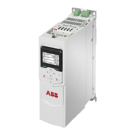
The chapter describes the operating principle and construction of the drive module. ACS880-M04 drive overview The ACS880-M04 is an air-cooled IP20 drive module for controlling asynchronous induction motors, permanent magnet motors and ABB synchronous reluctance motors. It is optimized for cabinet mounting. -
Page 30: Operation Principle
CHK-xx mains choke (see chapter Mains chokes page 155) UDC+ UDC– V1 W1 JFI-xx EMC filter (see chapter EMC filters on page 159) ACS880-M04 Rectifier – Capacitor bank drive Brake chopper (see chapter Resistor braking on page 173) V2 W2 R–... -
Page 31: Layout
Operation principle and hardware description 31 Layout General The DC input terminals are located at the top of the module and the AC output terminals are located at the bottom of the module. The ZCU-14 control unit is mounted onto the module. The control unit contains the basic I/Os and slots for optional I/O modules. -
Page 32: Module Layout - Frame R1
32 Operation principle and hardware description Module layout – Frame R1 (Note that frame R2 has a similar layout) Item Explanation DC (input) connection (obscured) Motor (output) connection (obscured) Grounding/clamping plates for power cables ZCU-14 control unit Power unit Slots for optional I/O modules I/O terminal blocks Grounding/clamping plate for control... -
Page 33: Module Layout - Frame R4
Operation principle and hardware description 33 Module layout – Frame R4 (Note that frame R3 has a similar layout.) Item Explanation DC (input) connection (under connector cover) Motor (output) connection (under connector cover) Grounding/clamping plates for power cables ZCU control unit Power unit Slots for optional I/O modules I/O terminal blocks... -
Page 34: Power Connections And Control Interfaces
34 Operation principle and hardware description Power connections and control interfaces Control unit (ZCU) Slot 1 / Slot 2 FIO-01 (Digital I/O extension) FIO-11 (Analog I/O extension) Slot 1 FIO-21 (Digital/Analog I/O extension) FEN-01 (Incremental [TTL] encoder interface) FEN-11 (Absolute encoder interface) FEN-21 (Resolver interface) FEN-31 (Incremental [HTL]... -
Page 35: Type Designation Label
Operation principle and hardware description 35 Type designation label This is a sample type designation label. No. Description Type designation, see Type designation key below. Degree of protection Frame (size) Nominal ratings, see Ratings on page 110. Valid markings S/N: Serial number in format MYYWWXXXX, where Manufacturer Year of manufacture: 15, 16, 17, ... -
Page 36: Type Designation Key
The table shows the primary drive variants. Sample type code: ACS880-M04-04A8-5+XXXX • The first digits from left indicate the basic configuration (ACS880-M04-04A8-5). • The optional selections are given thereafter, preceded by + signs (e.g. +L501). The main selections are described below. - Page 37 Operation principle and hardware description 37 Selection Alternatives I/O extensions L... +L500: FIO-11 analog I/O extension module and feedback +L501: FIO-01 digital I/O extension module interfaces +L502: FEN-31 HTL encoder interface module +L516: FEN-21 resolver interface module +L517: FEN-01 TTL encoder interface module +L518: FEN-11 absolute TTL encoder interface module +L519: FIO-21 analog/digital I/O extension module Programs...
- Page 38 38 Operation principle and hardware description...
-
Page 39: Planning The Cabinet Installation
Note: The installation examples in this manual are provided only to help the installer in designing the installation. Installation must always be designed and made according to applicable local laws and regulations. ABB does not assume any liability whatsoever for any installation which breaches the local laws and/or other regulations. -
Page 40: Cabinet Construction
40 Planning the cabinet installation Cabinet construction Cabinet frame Make sure... The cabinet frame is sturdy enough to carry the weight of the drive components, control circuitry and other equipment installed in it. The cabinet protects the drive module against contact and meets the requirements for dust and humidity. -
Page 41: Free Space Requirements
Planning the cabinet installation 41 Free space requirements The drive modules can be installed side by side. The alternate ways to install the modules are illustrated below. See the free space requirements table below. For dimensions of the drive modules, refer to chapter Dimension drawings page 181. -
Page 42: Horizontally Alone Or Side By Side Back Installation
42 Planning the cabinet installation Horizontally alone or side by side back installation Horizontally alone side installation This installation is recommended only with the R1 frame. For this kind of installation with other frames, use additional support. - Page 43 Planning the cabinet installation 43 Note: EMC filters of type JFI-x1 mounted directly above the drive module do not increase the free space requirements. (For EMC filters of type JFI-0x, see the dimension drawing of the filters on page 189.) 200 mm [7.9”] 300 mm [12”] Note: The temperature of the cooling air entering the unit must not exceed the...
-
Page 44: Cooling And Degrees Of Protection
44 Planning the cabinet installation Cooling and degrees of protection Check that... The cabinet has enough free space for the components for sufficient cooling. Observe the minimum clearances given for each component. The air inlets and outlets are equipped with gratings that guide the airflow, protect against contact, and prevent water splashes from entering the cabinet. -
Page 45: Preventing Recirculation Of Hot Air
Planning the cabinet installation 45 Preventing recirculation of hot air Cabinet (side view) AREA Main airflow out Air baffle plates COOL AREA Main airflow in Outside the cabinet Prevent hot air circulation outside the cabinet by leading the outcoming hot air away from the area where the inlet air to the cabinet is taken. -
Page 46: Cabinets With Multiple Modules
46 Planning the cabinet installation Cabinets with multiple modules The hot air from a drive module must not enter another module. In a cabinet with multiple modules, the practical way is to install a wall to separate the cool area (at the front part of the cabinet) from the hot area (back part). -
Page 47: Cabinet Heaters
Planning the cabinet installation 47 Cabinet heaters Use a cabinet heater if there is a risk of condensation in the cabinet. Although the primary function of the heater is to keep the air dry, it may also be required for heating at low temperatures. - Page 48 48 Planning the cabinet installation...
-
Page 49: Mechanical Installation
Mechanical installation 49 Mechanical installation Contents of this chapter The chapter describes the mechanical installation procedure of the drive. Contents of the package The drive is delivered in a cardboard box. To open, remove any banding and lift the top off the box. -
Page 50: Delivery Check And Drive Module Identification
Check that the box contains... ACS880-M04 drive module, with factory-installed options Three cable clamp plates (two for power cabling, one for control cabling) with screws Screw-type terminal blocks to be attached to the headers on the ZCU control unit and... -
Page 51: Before Installing The Drive
Mechanical installation 51 Before installing the drive Checking the installation site Before installation, check the installation site according to the requirements below. For frame details, refer to Dimension drawings on page 181. Check that... The frame details are according to the Dimension drawings from page 181. -
Page 52: Installing The Drive
52 Mechanical installation Installing the drive You can install the drive: • With screws on to a wall • To a DIN installation rail with the integrated lock. See the possible installation directions and free space requirements on page 41. ... -
Page 53: Installing Drive To A Din Installation Rail - Frames R1 And R2 Only
Mechanical installation 53 Installing drive to a DIN installation rail – Frames R1 and R2 only 1. Click the drive to the rail. To detach the drive, press the release lever on top of the drive as shown in the figure. 2. - Page 54 54 Mechanical installation...
-
Page 55: Planning The Electrical Installation
ABB does not assume any liability whatsoever for any installation which breaches the local laws and/or other regulations. If recommendations given by ABB are not followed, the drive may experience problems that the warranty does not cover. Checking the compatibility of the motor and drive Use an asynchronous AC induction motor or a permanent magnet motor with the drive. -
Page 56: Selecting The Supply Disconnecting Device
56 Planning the electrical installation Selecting the supply disconnecting device According to safety regulations, equip each drive with a supply disconnecting device. Install a hand-operated input disconnecting device between the AC power source and the drive. Note: You must be able to lock the disconnecting device to the open position for installation and maintenance work. -
Page 57: Selecting The Power Cables
Planning the electrical installation 57 Selecting the power cables Select the input power and motor cables according to local regulations: • The input power and the motor cables must be able to carry the corresponding load currents. For rated currents, see Ratings on page 110. -
Page 58: Typical Power Cable Sizes
The table below gives copper cable types with concentric copper shield for the drives with nominal current. The value separated by the plus sign means the diameter of the PE conductor. Drive type Frame size Cu cable type ACS880-M04 AWG/kcmil -03A0-2/5 3×1.5 + 1.5 -03A6-2/5 3×1.5 + 1.5 -04A8-2/5 3×1.5 + 1.5... -
Page 59: Alternative Power Cable Types
Planning the electrical installation 59 Alternative power cable types The recommended and the not allowed power cable types to be used with the drive are presented below. Recommended power cable types Symmetrical shielded cable with three phase conductors and a concentric PE conductor as the shield. -
Page 60: Motor Cable Shield
60 Planning the electrical installation Motor cable shield If the motor cable shield is used as the sole protective earth conductor of the motor, make sure that the conductivity of the shield is sufficient. See Selecting the power cables on page or see IEC 61439-1. - Page 61 Planning the electrical installation 61 Armored cable / shielded power cable Six-conductor (three phases and three ground) type MC continuous corrugated aluminum armor cable with symmetrical grounds is available from the following suppliers (trade names in parentheses): • Anixter Wire & Cable (Philsheath) •...
-
Page 62: Selecting The Control Cables
100 m (330 ft). If multiple panels or drives are connected, the total length of the panel bus must not exceed 100 m (330 ft). The cable type tested and approved by ABB is used in control panel option kits. Suitable cables are CAT 5e unshielded or shielded twisted pair cables. -
Page 63: Drive Composer Pc Tool Cable
Planning the electrical installation 63 Drive composer PC tool cable Connect the Drive composer PC tool to the drive through the USB port of the control panel. Use a USB type A (PC) - type B (control panel) cable. The maximum length of the cable is 3 m (9.8 ft). -
Page 64: Routing The Cables
64 Planning the electrical installation Routing the cables General rules • Route the motor cable away from other cables. The motor cables of several drives can be put in parallel next to each other. • Install the motor cable, input power cable and control cables on separate trays. •... -
Page 65: Separate Control Cable Ducts
Planning the electrical installation 65 Separate control cable ducts Put 24 V and 230 V (120 V) control cables in separate ducts unless the 24 V cable is insulated for 230 V (120 V) or insulated with an insulation sleeving for 230 V (120 V). 230 V (120 V) 24 V... -
Page 66: Implementing Thermal Overload And Short-Circuit Protection
Note: If you want to use circuit breakers, contact ABB for more information. Protecting the motor and motor cable in short-circuits The drive protects the motor cable and motor in a short-circuit situation when the motor cable is sized according to the nominal current of the drive. -
Page 67: Protecting The Motor Against Thermal Overload
The most common temperature sensors are: • motor sizes IEC180…225: thermal switch, eg, Klixon • motor sizes IEC200…250 and larger: PTC or Pt100. For more information, see ACS880-M04 firmware manual (3AXD50000030629 [English]). Protecting the drive against ground faults The drive is equipped with an internal ground fault protective function to protect the unit against ground faults in the motor and motor cable. -
Page 68: Implementing The Power-Loss Ride-Through Function
68 Planning the electrical installation Implementing the Power-loss ride-through function See ACS880-M04 firmware manual (3AXD50000030629 (English]). Using a safety switch between the drive and the motor Install a safety switch between the permanent magnet motor and the drive output. The safety switch isolates the motor from the drive during maintenance work on the drive. -
Page 69: Example Of A Bypass Connection
Planning the electrical installation 69 Example of a bypass connection Drive main switch Drive main contactor on/off control Bypass circuit breaker Motor power supply selection (drive or direct-on-line) Drive main contactor Start when motor is connected direct-on- line Bypass contactor Stop when motor is connected direct-on- line Drive output contactor... -
Page 70: Changing The Motor Power Supply From The Drive To Direct-On-Line
70 Planning the electrical installation Changing the motor power supply from the drive to direct-on-line 1. Stop the drive and the motor with the drive control panel (drive in local control mode) or with the external stop signal (drive in remote control mode). 2. -
Page 71: Protecting The Contacts Of Relay Outputs
Planning the electrical installation 71 Protecting the contacts of relay outputs Inductive loads (relays, contactors, motors) cause voltage transients when switched off. The voltage transients can connect capacitively or inductively to other conductors and cause a malfunction in the system. To protect the contacts of relay outputs, •... - Page 72 72 Planning the electrical installation...
-
Page 73: Electrical Installation
ABB does not assume any liability whatsoever for any installation that breaches the local laws and/or other regulations. If recommendations given by ABB are not followed, the drive system may experience problems that the warranty does not cover. -
Page 74: Removing The Cover Assembly
74 Electrical installation Removing the cover assembly Remove the cover assembly from the ZCU control unit, before installing the option modules or before connecting the control cables. See also the module layout diagram on page 31. -
Page 75: Checking The Insulation Of The Assembly
Protective Earth conductor. Use a measuring voltage of 1000 V DC. The insulation resistance of an ABB motor must exceed 100 Mohm (reference value at 25 °C or 77 °F). For the insulation resistance of other motors, please consult the manufacturer’s instructions. -
Page 76: Checking The Compatibility With It (Ungrounded) And Corner-Grounded Tn Systems
76 Electrical installation Checking the compatibility with IT (ungrounded) and corner-grounded TN systems The internal EMC filter is not suitable for use on an IT (ungrounded) system or on a corner-grounded TN system. Disconnect the EMC filter before connecting the drive to the supply network. -
Page 77: Connecting The Power Cables
Mains chokes (page 155). JFI-xx EMC filter (optional). See EMC filters (page 159). The UDC+/UDC– connectors can be used for common DC configurations. See page 82. ACS880-M04 UDC+ UDC– R– du/dt filter(s) (optional). See du/dt and common mode Optional brake... -
Page 78: Power Cable Connection Procedure
78 Electrical installation Power cable connection procedure See cabling drawing with tightening torques for all frame sizes on page 81. WARNING! Follow all Safety instructions on page 13. If you ignore them, injury or death, or damage to the equipment can occur. 1. - Page 79 Electrical installation 79 9. Crimp a cable lug onto each shield pigtail. Fasten the lugs to ground terminals. Note: Try to work out a compromise between the length of the pigtail and the length of unshielded phase conductors as both should ideally be as short as possible.
-
Page 80: Installing The Power Cable Clamp Plates
80 Electrical installation Installing the power cable clamp plates Two identical power cable clamp plates are included with the drive. The picture below depicts a frame size R1 drive; the installation is similar with other frame sizes. Note: Support the cables adequately within the installation enclosure, especially if not using the cable clamps. -
Page 81: Power Cable Connections
Electrical installation 81 Power cable connections Supply cable Cable clamp on bare shield 1.5 N·m (13 lbf·in) Below cable clamp, cover bare shield with insulating tape 1.5 N·m (13 lbf·in) 0.5 … 0.6 N·m (4.4 … 5.3 lbf·in) 0.5 … 0.6 N·m (4.4 …... -
Page 82: Dc Connection
DC connection The UDC+ and UDC– terminals are intended for common DC configurations of a number of ACS880-M04 drives, allowing regenerative energy from one drive to be utilised by the other drives in motoring mode. One or more drives are connected to the AC supply depending on the power requirement. - Page 83 Electrical installation 83 Each drive has an independent DC capacitor pre-charging circuit. UDC+ UDC- U1 V1 W1 ____ _ _ _ DC chokes* Pre-charging circuit ____ _ _ _ U2 V2 W2 * only for frames R3 and R4. DC connection ratings on page 123.
-
Page 84: Installing The Optional Modules
84 Electrical installation Installing the optional modules Optional modules such as fieldbus adapters, I/O extensions and encoder interfaces ordered using option codes (see Type designation key on page 36) are pre-installed at the factory. Instructions for installing additional modules into the slots on the ZCU control unit (see page for the available slots) are presented below. -
Page 85: Connecting The Control Unit
Electrical installation 85 Connecting the control unit ZCU-14 layout and connections Connec- Description tions X202 XRO1 XPOW External power input Analog inputs Analog outputs XRO2 XD2D Drive to drive link XRO1 Relay output RO1 XRO3 XRO2 Relay output RO2 XRO3 Relay output RO3 XPOW... -
Page 86: Control Connections To The Zcu Control Unit
86 Electrical installation Control connections to the ZCU control unit Relay outputs XRO1…XRO3 Ready 250 V AC / 30 V DC Running 250 V AC / 30 V DC Faulted(-1) 250 V AC / 30 V DC Fault External power input XPOW 24 V DC, 2 A min. -
Page 87: External Power Supply For The Control Unit (Xpow)
Electrical installation 87 Current [0(4)…20 mA, R = 100 ohm] or voltage [0(2)…10 V, R > 200 kohm] input selected by jumper Note: Changing the setting requires reboot of control unit. Current [0(4)…20 mA, R = 100 ohm] or voltage [0(2)…10 V, R >... -
Page 88: Di6 As A Ptc Sensor Input
88 Electrical installation DI6 as a PTC sensor input A PTC sensor can be connected to digital input DI6 for motor temperature measurement. See the example connection diagram below. • Alternatively, the sensor can be connected to FEN-xx encoder interface module. •... -
Page 89: Ai1 Or Ai2 As A Pt100 Or Kty84 Sensor Input
Electrical installation 89 AI1 or AI2 as a Pt100 or KTY84 sensor input Three Pt100 sensors or one KTY84 sensor for motor temperature measurement can be connected between an analog input and output as shown below. (Alternatively, you can connect the KTY to FEN-11 analog /I/O extension module or FEN-xx encoder interface module.) Do not connect both ends of the cable shields directly to ground. -
Page 90: Drive-To-Drive Link
90 Electrical installation Drive-to-drive link The drive-to-drive link is a daisy-chained RS-485 transmission line that allows basic master/follower communication with one master drive and multiple followers. Enable bus termination on the drives at the ends of the drive-to-drive link. On intermediate drives, disable bus termination. -
Page 91: Safe Torque Off
Electrical installation 91 Safe torque off For the drive to start, both connections (OUT1 to IN1 and IN2) must be closed. By default, the terminal block has jumpers to close the circuit. Remove the jumpers before connecting an external Safe torque off circuit to the drive. For information on the implementation of Safe torque off function, see chapter Safe torque off function (page 141). - Page 92 92 Electrical installation Digital inputs/outputs Connector pitch 5 mm, wire size 2.5 mm DIO1 and DIO2 As inputs: (XDIO:1 and XDIO:2) 24 V logic levels: “0” < 5 V, “1” > 15 V Input/output mode : 2.0 kohm selection by parameters. Filtering: 0.25 ms (ZCU) DIO1 can be configured as As outputs:...
- Page 93 Electrical installation 93 Control panel Connector: RJ-45 connection (X13) Cable length < 3 m The terminals of the control unit fulfil the Protective Extra Low Voltage (PELV) requirements. The PELV requirements of a relay output are not fulfilled if a voltage higher than 48 V is connected to the relay output.
-
Page 94: Ground Isolation Diagram (Zcu)
94 Electrical installation Ground isolation diagram (ZCU) XPOW +24VI +VREF -VREF AGND AI1+ Common mode voltage between AI1- channels +30 V AI2+ AI2- AGND AGND XD2D BGND XRO1, XRO2, XRO3 XD24 DIIL +24VD DICOM +24VD DIOGND XDIO DIO1 DIO2 XSTO OUT1 Ground... - Page 95 Electrical installation 95 *Ground selector (J6) settings All digital inputs share a common ground (DICOM connected to DIOGND). This is the default setting. Ground of digital inputs DI1…DI5 and DIIL (DICOM) is isolated from DIO signal ground (DIOGND). Isolation voltage 50 V.
-
Page 96: Connecting The Control Cables - All Frame Sizes
96 Electrical installation Connecting the control cables – all frame sizes For technical data and default I/O connections of the drive control unit, refer to Control connections to the ZCU control unit (page 86). 1. In the cabinet, remove shrouding wherever necessary to allow access to the cable entries and any trunking inside the cubicle. - Page 97 Electrical installation 97 6. Strip the cable ends and conductors. When connecting to the drive I/O, also remove the shield along with the outer sheathing, and use electrical tape or shrink tubing to contain the strands. Elsewhere, twist the outer shield strands into a bundle, crimp a lug onto it and connect it to the nearest chassis grounding point.
- Page 98 98 Electrical installation...
-
Page 99: Installation Checklist
The VAR (frames R1 and R2) and EMC/VAR1/VAR2 (frames R3 and R4) screws are removed if the drive is connected to an IT (ungrounded) or a corner grounded TN supply network. The capacitors are reformed if stored over one year (contact local ABB representative for more information). The drive is grounded properly. - Page 100 100 Installation checklist Check that... The supply (input power) is connected to U1/V1/W1 (UDC+/UDC- in case of a DC supply) and the terminals are tightened to specified torque. Appropriate supply (input power) fuses and disconnector are installed. The motor is connected to U2/V2/W2, and the terminals are tightened to the specified torque.
-
Page 101: Start-Up
Start-up 101 Start-up Contents of this chapter This chapter refers to the start-up instructions of the cabinet-installed drive. Start-up procedure 1. Make sure the installation of the drive is according to the Installation checklist page 2. Check that the motor and driven equipment are ready for start. 3. - Page 102 102 Start-up...
-
Page 103: Maintenance
Ignoring the safety instructions can cause injury or death. Maintenance intervals The table below lists the routine maintenance intervals recommended by ABB. Consult a local ABB Service representative for more details. You can also check on the Internet. Go to http://www.abb.com/drivesservices, select Drive Services, and Maintenance and Field Services. -
Page 104: Heatsink
40 °C (104 °F). DC capacitor replacement Every 6 years if the ambient Contact your local ABB temperature is higher than Service representative. 40 °C (104 °F) or if the drive is subjected to cyclic heavy load or continuous nominal load. -
Page 105: Cooling Fan
If the drive is operated in a critical part of a process, it is recommended to replace the immediately after these symptoms start appearing. Note: Replacement fans are available from ABB. Do not use spare parts other than ABB-specified spare parts. -
Page 106: Replacing Fan (Frames R3 And R4)
106 Maintenance Replacing fan (Frames R3 and R4) To repalce the fan in frames R3 and R4, follow these steps: 1. Remove the fan by releasing the retaining clip (arrowed) carefully using a screwdriver. 2. Pull the fan holder out. 3. -
Page 107: Reforming The Capacitors
Maintenance 107 Reforming the capacitors The capacitors must be reformed if the drive has been stored for a year or more. See manufacturing date on the Type designation label (see page 35). For information on reforming the capacitors, see Converter module capacitor reforming instructions (3BFE64059629 [English]). - Page 108 108 Maintenance...
-
Page 109: Technical Data
Technical data 109 Technical data Contents of this chapter This chapter contains the following technical specifications of the drive: Specifications See page... Ratings 110...112. Derating Dimensions and weights Losses, cooling data and noise Supply cable fuses Screwdrivers for the terminals of main circuit Supply cable fuses 119...121 AC input (supply) connection... -
Page 110: Ratings
110 Technical data Ratings Nominal ratings with 230 V AC supply Drive type Frame Input Output ratings ACS880-M04 size ratings Nominal No-overload Light-overload Heavy-duty use -03A0-2 2.1 3.5 0.37 0.37 0.5 0.37 0.5 -03A6-2 2.9 5.2 0.55 0.75 3.4 0.55 0.75 3.0... -
Page 111: Nominal Ratings With 460 V Ac Supply
Technical data 111 Drive type Frame Input Output ratings ACS880-M04 size ratings Nominal Light-overload Heavy-duty overload -050A-5 – -061A-5 – -078A-5 – -094A-5 – 3AXD10000434191 See symbol definitions on page 112. Nominal ratings with 460 V AC supply Drive type... -
Page 112: Nominal Ratings With 500 V Ac Supply
Note: To achieve the rated motor power given in the table, the rated current of the drive must be higher than or equal to the rated motor current. The DriveSize dimensioning tool available from ABB is recommended for selecting the drive, motor and gear combination. -
Page 113: Derating
Technical data 113 Derating The continuous output currents stated above must be derated if any of the following conditions apply: • ambient temperature exceeds 40 °C (+104°F) • drive is installed higher than 1000 m above sea level • parameter-adjustable motor noise level is set as low. Note: The final derating factor is a multiplication of all applicable derating factors. - Page 114 114 Technical data Deratings with 230 V AC supply in low motor noise mode Drive type Frame Input Output ratings ACS880-M04 size ratings Nominal Light-overload Heavy-duty overload -03A0-2 1.7 2.9 0.37 0.5 0.25 0.5 1.8 0.25 0.25 -03A6-2 2.4 4.4 0.37 0.5...
- Page 115 Technical data 115 Deratings with 460 V AC supply in low motor noise mode Drive type Frame Input Output ratings ACS880-M04 size ratings Nominal No-overload Light- Heavy-duty overload use -03A0-5 0.75 -03A6-5 0.75 -04A8-5 -06A0-5 -08A0-5 10.5 3 -010A-5 13.5 5 -014A-5 16.5 5...
-
Page 116: Dimensions And Weights
116 Technical data Dimensions and weights Frame H1 - Height H2 - Height W - Width D - Depth (with Weight size (without cable (with cable control panel) clamp plates) clamp plates) 14.33 18.89 3.54 9.33 14.97 18.89 3.94 12.40 11.9 18.37 21.96... -
Page 117: Losses, Cooling Data And Noise
Technical data 117 Losses, cooling data and noise Drive type Power loss Airflow Noise ACS880- W (BTU/h) dB(A) /min) Load 100% -03A0-2 66 (226) 71 (244) 77 (264) 84 (287) 91 (312) 24 (14) -03A6-2 66 (226) 73 (247) 80 (272) 88 (300) 97 (332) 24 (14) -
Page 118: Supply Cable Fuses
See also chapter Planning the electrical installation on page 55. Note: Fuses with a higher current rating must not be used. Drive type Input IEC fuse UL fuse Cross-sectional ACS880-M04 current area of cable Rated Volt- Class Rated Volt- current current class -03A0-2, -03A0-5 4.0*... -
Page 119: Gg Fuses
Technical data 119 gG fuses Drive type Manufacturer Type Fuse size (@500V) ACS880-M04 UN = 230 V -03A0-2 OFAF000H6 -03A6-2 OFAF000H6 -04A8-2 OFAF000H10 -06A0-2 OFAF000H10 -08A0-2 OFAF000H16 -010A-2 OFAF000H16 -014A-2 1500 OFAF000H20 -018A-2 2550 OFAF000H25 -025A-2 2550 OFAF000H25 -030A-2... -
Page 120: Gr Fuses
120 Technical data gR fuses Drive type Manufacturer Type Fuse size (@500V) ACS880-M04 UN = 230 V -03A0-2 Bussmann 170M2693 -03A6-2 Bussmann 170M2693 -04A8-2 Bussmann 170M2693 -06A0-2 Bussmann 170M2693 -08A0-2 Bussmann 170M2693 -010A-2 Bussmann 170M2693 -014A-2 Bussmann 170M2694 -018A-2... -
Page 121: Ar Fuses
Technical data 121 aR fuses Drive type Manufacturer Type Fuse size (@500V) ACS880-M04 UN = 230 V -03A0-2 Bussmann 170M1561 -03A6-2 Bussmann 170M1561 -04A8-2 Bussmann 170M1561 -06A0-2 Bussmann 170M1561 -08A0-2 Bussmann 170M1561 -010A-2 Bussmann 170M1561 -014A-2 Bussmann 170M1563 -018A-2... -
Page 122: Ac Input (Supply) Connection
122 Technical data AC input (supply) connection Voltage (U 200…240 V AC +/-10%, 3-phase 380…500 V AC +10%/-15%, 3-phase Network type Grounded (TN, TT) or ungrounded (IT). Note: If the installation site is higher than 2000 m (6600 ft) above sea level, connection of the drive to an ungrounded (IT) or corner-grounded delta network is not allowed. -
Page 123: Dc Connection
Technical data 123 DC connection Voltage 243…356 V DC (ACS880-M04-xxxx-2 drives) 436…743 V DC (ACS880-M04-xxxx-5 drives) Ratings, fuse recommenda- Drive IEC fuse UL fuse tions type (A) (µF) Rated Voltage Class Rated Voltage Class ACS880- current current -xxxx-2/5 -03A0 3.3 120 -03A6 3.9 120... -
Page 124: Motor Connection
124 Technical data Motor connection Motor types Asynchronous induction motors, permanent magnet motors, ABB synchronous reluctance motors Frequency 0…500 Hz Current See section Ratings. Switching 3 kHz (default) frequency Maximum motor Frames R1 and R2: 150 m (492 ft)* cable length... -
Page 125: Zcu Control Unit
Technical data 125 ZCU control unit Power supply Connector pitch 5 mm, wire size 2.5 mm (XPOW) 24 V (±10%) DC, 2 A External power input. Two supplies can be connected to BCU for redundancy. Relay outputs RO1…RO3 (XRO1… Connector pitch 5 mm, wire size 2.5 mm XRO3) 250 V AC / 30 V DC, 2 A Protected by varistors... - Page 126 126 Technical data Digital inputs/outputs DIO1 and DIO2 Connector pitch 5 mm, wire size 2.5 mm (XDIO:1 and XDIO:2) As inputs: Input/output mode selection by 24 V logic levels: “0” < 5 V, “1” > 15 V parameters. : 2.0 kohm Filtering: 0.25 ms (ZCU), 1 ms (BCU) DIO1 can be configured as a frequency input (0…16 kHz with hardware filtering of...
- Page 127 Technical data 127 Drive-to-drive link Connector pitch 5 mm, wire size 2.5 mm (XD2D) Physical layer: RS-485 Termination by switch or jumper Safe torque off connection Connector pitch 5 mm, wire size 2.5 mm (XSTO) Input voltage range: -3…30 V DC Logic levels: “0”...
-
Page 128: Ground Isolation Diagram (Zcu)
128 Technical data Ground isolation diagram (ZCU) XPOW +24VI +VREF -VREF AGND AI1+ Common mode voltage between AI1- channels +30 V AI2+ AI2- AGND AGND XD2D BGND XRO1, XRO2, XRO3 XD24 DIIL +24VD DICOM +24VD DIOGND XDIO DIO1 DIO2 XSTO OUT1 Ground... -
Page 129: Efficiency
Technical data 129 *Ground selector (J6) settings All digital inputs share a common ground (DICOM connected to DIOGND). This is the default setting. Ground of digital inputs DI1…DI5 and DIIL (DICOM) is isolated from DIO signal ground (DIOGND). Isolation voltage is 50 V. Efficiency Approximately 98% at nominal power level Cooling... -
Page 130: Ambient Conditions
130 Technical data Ambient conditions Environmental limits for the drive are given below. The drive must be used in a heated, indoor, controlled environment. Operation Storage Transportation installed for stationary in the protective in the protective package package Installation site Non-corner grounded altitude TN and TT systems: 0... - Page 131 Technical data 131 Sinusoidal Tested according to – – vibration IEC 60721-3-3, (IEC 60721-3-3) mechanical conditions: Class 3M4 2…9 Hz: 3.0 mm (0.12”) 9…200 Hz: 10 m/s (33 ft/s Shock – According to ISTA 1A. According to ISTA 1A. (IEC 60068-2-27, Max.
-
Page 132: Materials
IEC 62635 guidelines. To aid recycling, plastic parts are marked with an appropriate identification code. Contact your local ABB distributor for further information on environmental aspects and recycling instructions for professional recyclers. End of life treatment must follow international and local regulations. -
Page 133: Applicable Standards
Technical data 133 Applicable standards The drive complies with the following standards. The compliance with the European Low Voltage Directive is verified according to standard EN 61800-5-1. EN 61800-5-1:2007 Adjustable speed electrical power drive systems. Part 5-1: Safety requirements – electrical, thermal and energy. -
Page 134: Ce Marking
134 Technical data CE marking A CE mark is attached to the drive to verify that the drive follows the provisions of the European Low Voltage, EMC and RoHS Directives. The CE marking also verifies that the drive, in regard to its safety functions (such as Safe torque off), conforms with the Machinery Directive as a safety component. -
Page 135: Compliance With The En 61800-3:2004
Technical data 135 Compliance with the EN 61800-3:2004 Definitions EMC stands for Electromagnetic Compatibility. It is the ability of electrical/electronic equipment to operate without problems within an electromagnetic environment. Likewise, the equipment must not disturb or interfere with any other product or system within its locality. -
Page 136: Category C3
Supply transformer Neighbouring network Static screen Point of measurement Low voltage Low voltage Equipment Drive (victim) Equipment Equipment 2. An EMC plan for preventing disturbances is drawn up for the installation. A template is available from the local ABB representative. - Page 137 Technical data 137 3. The motor and control cables are selected as specified in this manual. 4. The drive is installed according to the instructions given in this manual. WARNING! A drive of category C4 is not intended to be used on a low- voltage public network which supplies domestic premises.
-
Page 138: Ul Marking
For installation in Canada, also obey any additional provincial codes. Note: For installation in the United states, do not use circuit breakers without fuses. For suitable circuit breakers, contact your local ABB representative. The drive provides motor overload protection. For the adjustments, see the Firmware manual. -
Page 139: Disclaimers
ABB and its affiliates are not liable for damages and/or losses related to such security breaches, any unauthorized access,... - Page 140 140 Technical data...
-
Page 141: The Safe Torque Off Function
The Safe torque off function 141 The Safe torque off function Contents of this chapter This chapter describes the Safe torque off (STO) function of the drive modules and gives instructions for its use. Description The Safe torque off function can be used, for example, to construct safety or supervision circuits that stop the drive in case of danger (such as an emergency stop circuit). -
Page 142: Compliance Of Sto Function With The European Machinery Directive
142 The Safe torque off function Compliance of STO function with the European Machinery Directive The Safe torque off function of the drive complies with these standards: Standard Name EN 60204-1:2006 + AC:2010 Safety of machinery – Electrical equipment of machines – Part 1: General requirements IEC 61326-3-1:2008 Electrical equipment for measurement, control and laboratory... -
Page 143: Connecting The Sto
The Safe torque off function 143 Connecting the STO See STO control unit connections in Connecting the control unit on page 85. The following diagrams present examples of Safe torque off wiring for • a single drive unit (page 144) •... -
Page 144: Sto Wiring - Single Drive Unit (Internal Power Supply)
144 The Safe torque off function STO wiring – single drive unit (internal power supply) Drive unit Control unit OUT1 +24 V SGND Control logic UDC+ U2, V2, W2 UDC–... -
Page 145: Sto Wiring - Multiple Drive Units (Internal Power Supply)
The Safe torque off function 145 STO wiring – multiple drive units (internal power supply) Drive unit XSTO Control unit OUT1 +24 V SGND Drive unit XSTO Control unit OUT1 SGND Drive unit XSTO Control unit OUT1 SGND... -
Page 146: Sto Wiring - Multiple Drive Units (External Power Supply)
146 The Safe torque off function STO wiring – multiple drive units (external power supply) 24 V DC Drive unit – Control unit XSTO OUT1 +24 V SGND Drive unit Control unit XSTO OUT1 SGND Drive unit Control unit XSTO OUT1 SGND... -
Page 147: Sto Operation Principle
The Safe torque off function 147 STO operation principle 1. The Safe torque off activates (the activation switch is opened, or safety relay contacts open). 2. The STO inputs on the drive control unit de-energize. 3. The control unit cuts off the control voltage from the drive IGBTs. 4. -
Page 148: Sto Acceptance Test Procedure
148 The Safe torque off function STO acceptance test procedure After wiring the Safe torque off function, validate its operation as follows. • Note: If an FSO-xx safety functions module is installed, refer to its documentation. Action WARNING! Follow the Safety instructions on page 13. -
Page 149: Using The Sto Function
The Safe torque off function 149 Using the STO function 1. Open the activation switch, or activate the safety functionality that is wired to the STO connection. • The STO inputs on the drive control unit de-energize, and the drive control unit cuts off the control voltage from the drive IGBTs. - Page 150 150 The Safe torque off function Notes: • If a running drive is stopped by using the Safe torque off function, the drive cuts- off the motor supply voltage and the motor coasts to a stop. If this causes danger or is not otherwise acceptable, stop the drive and machinery using the appropriate stop mode before activating the Safe torque off function.
-
Page 151: Sto Function Maintenance
STO acceptance test procedure on page 148. Record all maintenance and proof test activities in the machine logbook. Note: Use only ABB approved spare parts. Competency for STO operations The maintenance and proof test activities of the safety function must be carried out by a competent person with adequate expertise and knowledge of the safety function as well as functional safety, as required by IEC 61508-1 clause 6. -
Page 152: Sto Fault Tracing
See the drive firmware manual for the indications generated by the drive, and for details on directing fault and warning indications to an output on the control unit for external diagnostics. Any failures of the Safe torque off function must be reported to ABB. Relevant failure modes The STO trips spuriously (safe failure) and does not activate when requested. -
Page 153: Sto Data
The Safe torque off function 153 STO data Safety data The safety data for the Safe torque off function is given below. Note: The safety data is calculated for redundant use, and does not apply if both STO channels are not used. Frame SIL/ SC PL SFF PFH... -
Page 154: Sto Abbreviations
154 The Safe torque off function STO abbreviations Abbreviation Reference Description Cat. EN ISO 13849-1 Classification of the safety-related parts of a control system in respect of their resistance to faults and their subsequent behavior in the fault condition, and which is achieved by the structural arrangement of the parts, fault detection and/or by their reliability. -
Page 155: Mains Chokes
Mains chokes 155 Mains chokes Contents of this chapter This chapter describes how to select and install mains chokes for the drive module. The chapter also contains the relevant technical data. When is a mains choke required? With frames R1 and R2, the need for an external choke should be determined on a case-by-case basis. -
Page 156: Selecting A Mains Choke
156 Mains chokes Selecting a mains choke Drive type Type Inductance ACS880-M04 µH -03A0-2, -03A0-5 CHK-01 6370 -03A6-2, -03A6-5 -04A8-2, -04A8-5 CHK-02 4610 -06A0-2, -06A0-5 -08A0-2, -08A0-5 -010A-2, -010A-5 CHK-03 2700 -014A-2, -014A-5 -018A-2, -018A-5 CHK-04 1475 -025A-2, -025A-5 -030A-2, -030A-5... -
Page 157: Guidelines For Installing The Mains Choke
• Keep the cable between the drive and the choke as short as possible. WARNING! The surface of the mains choke becomes hot when in use. Connecting the mains choke AC supply DC supply CHK-xx mains choke – JFI-xx EMC filter (if present) ACS880-M04 UDC+ UDC-... - Page 158 158 Mains chokes...
-
Page 159: Emc Filters
EMC filters 159 EMC filters Contents of this chapter This chapter describes how to select and install EMC filters for the drive module. The chapter also contains the relevant technical data. EMC standards The EMC product standard (EN 61800-3:2004) covers the specific EMC requirements stated for drives (tested with motor and cable) within the EU. -
Page 160: Emc Filter Emission Limits
160 EMC filters EMC filter emission limits The emission limits are comparable according to the following general EMC standards. EN 61800-3:2004, EN 55011, product family standard for industrial, scientific product standard and medical (ISM) equipment Category C1 Group 1 Class B Category C2 Group 1 Class A Category C3... -
Page 161: Selecting Emc Filters
EMC filters 161 Selecting EMC filters Drive type Filter type ACS880-M04 EN 61800-3:2004 Category C3 EN 61800-3: 2004 Category C2 -03A0-2, -03A0-5 Option code +E200 (external filter JFI-02* JFI-A1) -03A6-2, -03A6-5 -04A8-2, -04A8-5 -06A0-2, -06A0-5 -08A0-2, -08A0-5 -010A-2, -010A-5 Option code +E200 (external filter... -
Page 162: Installing Emc Filters - Jfi-A1/Jfi-B1 (Frame R1/R2, Category C3)
• Connect the filter directly to the drive input connectors. • For optimal operation of the filter, mount the drive and the filter on the same conductive surface. JFI-x1 filter connection diagram AC supply DC supply CHK-xx mains choke (if present) – JFI-x1 EMC filter ACS880-M04 UDC+ UDC-... -
Page 163: Installing The Jfi-A1 Filter
EMC filters 163 Installing the JFI-A1 filter To install the JFI-A1 EMC filter, 1. Remove the UDC+/- and U1/V1/W1 terminal blocks (1), and the upper power cable clamp plate (2) from the drive. 2. Fasten the mounting bracket (3) to the drive module base with two screws (4). Tighten to 1.5 N·m (13 lbf·in). - Page 164 164 EMC filters 7. Attach the terminal blocks to the filter.
-
Page 165: Installing The Jfi-B1 Filter
EMC filters 165 Installing the JFI-B1 filter To install the JFI-B1 EMC filter, 1. Remove the UDC+/- and U1/V1/W1 terminal blocks (1), and the upper power cable clamp plate (2) from the drive. 2. Push the filter into the connectors. 3. - Page 166 166 EMC filters 6. Attach the terminal blocks to the filter.
-
Page 167: Installing Emc Filter - Jfi-0X (Frames R1
• Ensure the filter does not block the airflow through the drive module. • Keep the cable between the drive and the filter as short as possible. JFI-0x filter connection diagram AC supply CHK-xx mains choke (if present) JFI-0x EMC filter L1’ L2’ L3’ ACS880-M04... - Page 168 168 EMC filters...
-
Page 169: Du/Dt And Common Mode Filtering
Use the, • optional ABB du/dt filters to avoid stress on motor insulation • common mode filters to reduce bearing currents. Note: To avoid damage to the motor bearings, select and install the cables according... -
Page 170: Selecting The Du/Dt Filters
For more information on common mode filtering, contact your local ABB representative. Contact the motor manufacturer for information on the motor construction. -
Page 171: Additional Requirements For The Braking Applications
Common mode filter N-end bearing: insulated motor non-drive end bearing Additional requirements for ABB motors of types other than M2_, M3_, M4_, HX_ and AM_ Use the selection criteria given for non-ABB motors. ... -
Page 172: Du/Dt Filters Data
-050A-2, -050A-5 -061A-2, -061A-5 -078A-2, -078A-5 -094A-2, -094A-5 NOCH0120-60 (1-phase; three filters included in kit) 3AXD10000434191 Common mode filter types Contact your local ABB representative. du/dt filters dimensions and weights Filter type Height Width Depth Weight mm (inches) -
Page 173: Resistor Braking
Selecting brake choppers and resistors Brake choppers The ACS880-M04 (frames R1…R4) drives have a built-in brake chopper as standard equipment to handle the energy generated by a decelerating motor. When the brake chopper is enabled and a resistor is connected, the chopper starts conducting when the DC link voltage of the drive reaches U - 30 V. -
Page 174: Brake Resistors
1. maximum power generated by the motor during braking 2. continuous power based on the braking duty cycle 3. braking energy during the duty cycle. Pre-selected resistors are available from ABB as shown in the Brake resistors data table on page 177. If the listed resistor is not sufficient for the application, a custom resistor can be selected within the limits imposed by the internal brake chopper of the ACS880-M04. -
Page 175: Brake Choppers Data Table
Resistor braking 175 Brake choppers data table The ratings apply at an ambient temperature of 40 °C (104 °F). Drive type Internal brake chopper ACS880-M04 Pbr10 Pbr10 brcont brcont brmax (kW) (kW) (kW) (kW) (kW) (kW) (kW) (ohm) -03A0-2 0.45 0.15... - Page 176 176 Resistor braking The drive (drive and chopper) withstands this continuous braking power. Braking is brcont = considered continuous if braking time exceeds 30 seconds. = Maximum braking power of the drive (drive and chopper). The drive (drive and brmax chopper) withstands this braking power for 1 second within every 10 seconds.
-
Page 177: Brake Resistors Data Table
Resistor braking 177 Brake resistors data table The ratings apply at an ambient temperature of 40°C (104°F). Drive type Example brake resistor Example brake resistor ACS880-M04 JBR-xx SACExxxxx Type Type pulse Rcont (ohm) (kJ) (ohm) (kW) (kJ) -03A0-2, -03A0-5 JBR-01... -
Page 178: Brake Resistors Dimensions
178 Resistor braking Brake resistors dimensions See dimensions drawings of Brake resistors (type JBR-xx) on page 191. For details of dimensions, wire sizes and tightening torques, see Brake resistor - JBR-xx dimensions on page 192. -
Page 179: Installing And Wiring Brake Resistors
Below is a simple example wiring diagram. L1 L2 L3 Fuses U1 V1 W1 Resistor thermal switch Θ ACS880-M04 Main contactor... -
Page 180: Commissioning The Braking Circuit
180 Resistor braking Commissioning the braking circuit For more information, see the firmware manual. 1. Enable the brake chopper function. Please note that a brake resistor must be connected when the chopper is enabled from group 43 Brake chopper. 2. Switch Off the overvoltage control of the drive with parameter 30.30 Overvoltage control. - Page 181 Dimension drawings 181 Dimension drawings Contents of this chapter The dimension drawings of the ACS880-M04 drive (frame sizes R1, R2, R3 and R4) and the related accessories are show below. The dimensions are given in millimetres and inches. See, •...
-
Page 182: Dimension Drawings 182
Dimension drawings 182 Frame size R1... -
Page 183: Frame Size R2
Dimension drawings 183 Frame size R2... -
Page 184: Frame Size R3
Dimension drawings 184 Frame size R3... -
Page 185: Frame Size R4
Dimension drawings 185 Frame size R4... -
Page 186: Mains Chokes (Type Chk-0X)
Dimension drawings 186 Mains chokes (type CHK-0x) 68906903 Mains choke – CHK-xx dimensions Parameter Choke type CHK-01 CHK-02 CHK-03 CHK-04 dim A mm (in.) 120 (4.72) 150 (5.91) 150 (5.91) 150 (5.91) dim B mm (in.) 146 (5.75) 175 (6.89) 175 (6.89) 175 (6.89) dim C mm (in.) -
Page 187: Emc Filters (Type Jfi-X1)
187 Dimension drawings EMC filters (type JFI-x1) JFI-A1... -
Page 188: Jfi-B1
Dimension drawings 188 JFI-B1... -
Page 189: Emc Filters (Type Jfi-0X)
189 Dimension drawings EMC filters (type JFI-0x) -
Page 190: Emc Filter - Jfi-Xx Dimensions
Dimension drawings 190 EMC filter – JFI-xx dimensions Parameter Filter type JFI-02 JFI-03 JFI-05 JFI-07 Dim. A mm (in.) 250 (9.84) 250 (9.84) 250 (9.84) 270 (10.63) Dim. B mm (in.) 45 (1.77) 50 (1.97) 85 (3.35) 90 (3.54) Dim. -
Page 191: Brake Resistors (Type Jbr-Xx)
191 Dimension drawings Brake resistors (type JBR-xx) -
Page 192: Brake Resistor - Jbr-Xx Dimensions
Dimension drawings 192 Brake resistor - JBR-xx dimensions Parameter Resistor type JBR-01 JBR-03 JBR-04 JBR-05 JBR-06 Dim. A mm (in.) 295 (11.61) 340 (13.39) – – – Dim. B mm (in.) 155 (6.10) 200 (7.87) – – – Dim. C mm (in.) 125 (4.92) 170 (6.69) –... - Page 193 193 Dimension drawings...
-
Page 194: Further Information
Product and service inquiries Address any inquiries about the product to your local ABB representative, quoting the type designation and serial number of the unit in question. A listing of ABB sales, support and service contacts can be found by navigating to www.abb.com/searchchannels. - Page 195 Contact us www.abb.com/drives www.abb.com/drivespartners 3AXD50000028613 Rev A (EN) 2016-04-11...