Lenovo ThinkSystem SR650 V2 Maintenance Manual
Hide thumbs
Also See for ThinkSystem SR650 V2:
- Reference (212 pages) ,
- Problem determination and service manual (15 pages)
Table of Contents
Advertisement
Quick Links
Advertisement
Table of Contents

Related Manuals for Lenovo ThinkSystem SR650 V2


Summary of Contents for Lenovo ThinkSystem SR650 V2
- Page 1 ThinkSystem SR650 V2 Maintenance Manual Machine Types: 7Z72 and 7Z73...
- Page 2 Before using this information and the product it supports, be sure to read and understand the safety information and the safety instructions, which are available at: http://thinksystem.lenovofiles.com/help/topic/safety_documentation/pdf_files.html In addition, ensure that you are familiar with the terms and conditions of the Lenovo warranty for your server, which can be found at: http://datacentersupport.lenovo.com/warrantylookup First Edition (May 2021) ©...
-
Page 3: Table Of Contents
16 x Anybay front drive bays ..131 24 x Anybay front drive bays ..132 Chapter 1. ThinkSystem SR650 V2 8 x Anybay and 8 x NVMe front drive bays. . . 133 (7Z72 and 7Z73) . - Page 4 Install a hot-swap drive ..227 Remove a super capacitor module from the air baffle ....318 Front drive backplane replacement .
- Page 5 Network problems ... . 408 Index ....425 Observable problems ... 409 © Copyright Lenovo 2021...
- Page 6 ThinkSystem SR650 V2Maintenance Manual...
-
Page 7: Safety
Vor der Installation dieses Produkts die Sicherheitshinweise lesen. Prima di installare questo prodotto, leggere le Informazioni sulla Sicurezza. Les sikkerhetsinformasjonen (Safety Information) før du installerer dette produktet. Antes de instalar este produto, leia as Informações sobre Segurança. © Copyright Lenovo 2021... -
Page 8: Safety Inspection Checklist
1 & IEC 60950-1, the standard for Safety of Electronic Equipment within the Field of Audio/Video, Information Technology and Communication Technology. Lenovo assumes you are qualified in the servicing of equipment and trained in recognizing hazards energy levels in products. Access to the equipment is by the use of a tool, lock and key, or other means of security, and is controlled by the authority responsible for the location. - Page 9 Click the Power tab to see all line cords. • Make sure that the insulation is not frayed or worn. 3. Check for any obvious non-Lenovo alterations. Use good judgment as to the safety of any non-Lenovo alterations. 4. Check inside the server for any obvious unsafe conditions, such as metal filings, contamination, water or other liquid, or signs of fire or smoke damage.
- Page 10 ThinkSystem SR650 V2Maintenance Manual viii...
-
Page 11: Chapter 1. Thinksystem Sr650 V2 (7Z72 And 7Z73)
XCC network access label The Lenovo XClarity Controller (XCC) network access label is attached to the pull-out information tab on the front of the server. The label provides the default host name and default IPv6 link local address of the XCC. -
Page 12: Specifications
Scan the QR code with a mobile device and a QR code reader application to get quick access to the Lenovo Service Web site for this server. The Lenovo Service Information Web site provides additional information for parts installation and replacement videos, and error codes for server support. -
Page 13: Technical Specifications
– 6 TB using both 3DS RDIMMs and PMEMs in App Direct Mode Note: The operating speed and total memory capacity depend on the processor model and UEFI settings. For a list of supported memory options, see https://static.lenovo.com/us/en/serverproven/ index.shtml Chapter 1 ThinkSystem SR650 V2 (7Z72 and 7Z73) - Page 14 Table 1. Technical specifications (continued) Specification Description Supported and certified operating systems: • Microsoft Windows Server • Red Hat Enterprise Linux • SUSE Linux Enterprise Server • VMware ESXi Operating systems • Canonical Ubuntu Complete list of operating systems: https://lenovopress.com/osig OS deployment instructions: See “Deploy the operating system”...
- Page 15 – ThinkSystem RAID 940-8i 4GB Flash PCIe Gen4 12Gb Adapter for U.3 (Trimode) – ThinkSystem RAID 940-8i 8GB Flash PCIe Gen4 12Gb Adapter for U.3 (Trimode) – ThinkSystem RAID 940-16i 8GB Flash PCIe Gen4 12Gb Adapter for U.3 (Trimode) Chapter 1 ThinkSystem SR650 V2 (7Z72 and 7Z73)
- Page 16 Table 1. Technical specifications (continued) Specification Description – ThinkSystem 4-Port PCIe Gen4 NVMe Retimer Adapter – ThinkSystem 1611-8P PCIe Gen4 Switch Adapter • Expander: ThinkSystem 48 port 12Gb Internal Expander* Notes: • *Customer form factor (CFF) adapters that are supported only for server models with 2.5- inch front drive bays.
-
Page 17: Environmental Specifications
Class A3, or Class A4 specifications with certain thermal restrictions. For detailed thermal information, see “Thermal rules” on page 192. System performance may be impacted when operating temperature is outside permitted conditions. Chapter 1 ThinkSystem SR650 V2 (7Z72 and 7Z73) - Page 18 Ambient temperature • Operating – ASHRAE class A2: 10°C to 35°C (50°F to 95°F) The maximum ambient temperature decreases by 1°C for every 300 m (984 ft) increase in altitude above 900 m (2,953 ft) – ASHRAE class A3: 5°C to 40°C (41°F to 104°F) The maximum ambient temperature decreases by 1°C for every 175 m (574 ft) increase in altitude above 900 m (2,953 ft) –...
- Page 19 If Lenovo determines that the levels of particulates or gases in your environment have caused damage to the device, Lenovo may condition provision of repair or replacement of devices or parts on implementation of appropriate remedial measures to mitigate such environmental contamination.
-
Page 20: Firmware Updates
CPU. • Out-of-band update. The installation or update is performed by the Lenovo XClarity Controller collecting the update and then directing the update to the target subsystem or device. Out-of-band updates have no dependency on an operating system executing on the core CPU. - Page 21 Best practices related to updating firmware is available at the following location: http://lenovopress.com/LP0656 See the following table to determine the best Lenovo tool to use for installing and setting up the firmware: Note: The server UEFI settings for option ROM must be set to Auto or UEFI to update firmware using Lenovo XClarity Administrator or Lenovo XClarity Essentials.
- Page 22 The latest firmware can be found at the following site: https://datacentersupport.lenovo.com/products/servers/thinksystem/sr650v2/downloads/driver-list • Lenovo XClarity Provisioning Manager V3 From Lenovo XClarity Provisioning Manager V3, you can update the Lenovo XClarity Controller firmware, the UEFI firmware, and the Lenovo XClarity Provisioning Manager V3 software. ThinkSystem SR650 V2Maintenance Manual...
- Page 23 • Lenovo XClarity Controller If you need to install a specific update, you can use the Lenovo XClarity Controller interface for a specific server. Notes: – To perform an in-band update through Windows or Linux, the operating system driver must be installed and the Ethernet-over-USB (sometimes called LAN over USB) interface must be enabled.
-
Page 24: Turn On The Server
If you are managing multiple servers using the Lenovo XClarity Administrator, you can update firmware for all managed servers through that interface. Firmware management is simplified by assigning firmware- compliance policies to managed endpoints. When you create and assign a compliance policy to managed endpoints, Lenovo XClarity Administrator monitors changes to the inventory for those endpoints and flags any endpoints that are out of compliance. -
Page 25: Turn Off The Server
Turn off the server The server remains in a standby state when it is connected to a power source, allowing the Lenovo XClarity Controller to respond to remote power-on requests. To remove all power from the server (power status LED off), you must disconnect all power cables. - Page 26 ThinkSystem SR650 V2Maintenance Manual...
-
Page 27: Chapter 2. Server Components
• “Front view with eight 3.5-inch front drive bays” on page 24 • “Front view with twelve 3.5-inch front drive bays” on page 25 • “Front view with 3.5-inch front drive bays (backplane-less)” on page 26 © Copyright Lenovo 2021... - Page 28 Front view with eight 2.5-inch front drive bays (model 1) Figure 4. Front view with eight 2.5-inch front drive bays (model 1) Table 4. Components on the front of the server Callout Callout “External diagnostics connector” on page 37 “VGA connector (optional)” on page 51 “Drive activity LED”...
- Page 29 Front view with eight 2.5-inch front drive bays (model 2) Table 5. Components on the front of the server Callout Callout “External diagnostics connector” on page 37 “VGA connector (optional)” on page 51 “Drive activity LED” on page 50 “Drive status LED” on page 50 Drive bay filler “Front I/O assembly (on media bay)”...
- Page 30 Front view with sixteen 2.5-inch front drive bays (model 1) Table 6. Components on the front of server models Callout Callout “External diagnostics connector” on page 37 “VGA connector (optional)” on page 51 “Drive activity LED” on page 50 “Drive status LED” on page 50 Drive bay filler “Front I/O assembly (on rack latch)”...
- Page 31 Front view with sixteen 2.5-inch front drive bays (model 2) Table 7. Components on the front of the server Callout Callout “External diagnostics connector” on page 37 “VGA connector (optional)” on page 51 “Drive activity LED” on page 50 “Drive status LED” on page 50 “Front I/O assembly (on media bay)”...
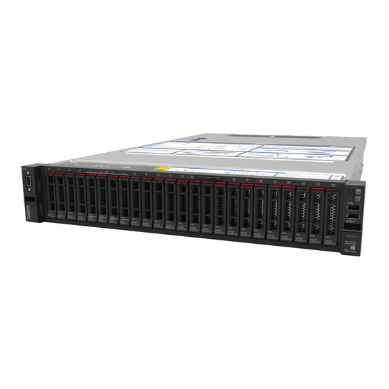
- Page 32 Front view with twenty-four 2.5-inch front drive bays Table 8. Components on the front of server models Callout Callout “External diagnostics connector” on page 37 “VGA connector (optional)” on page 51 “Drive activity LED” on page 50 “Drive status LED” on page 50 “Front I/O assembly (on rack latch)”...
- Page 33 Front view with 2.5-inch front drive bays (backplane-less) The following illustration shows the front view of server models with 2.5-inch front drive bays (backplane- less). Table 9. Components on the front of server models Callout Callout “External diagnostics connector” on page 37 “VGA connector (optional)”...
- Page 34 Front view with eight 3.5-inch front drive bays Table 10. Components on the front of server models Callout Callout “External diagnostics connector” on page 37 “VGA connector (optional)” on page 51 “Drive activity LED” on page 50 “Drive status LED” on page 50 Drive bay filler “Front I/O assembly (on rack latch)”...
- Page 35 Front view with twelve 3.5-inch front drive bays Table 11. Components on the front of server models Callout Callout “External diagnostics connector” on page 37 “VGA connector (optional)” on page 51 “Drive activity LED” on page 50 “Drive status LED” on page 50 “Front I/O assembly (on rack latch)”...
- Page 36 Front view with 3.5-inch front drive bays (backplane-less) Table 12. Components on the front of server models Callout Callout “External diagnostics connector” on page 37 “VGA connector (optional)” on page 51 “Front I/O assembly (on rack latch)” on page 27 Rack latch (right) “Pull-out information tab”...
-
Page 37: Front Io Assembly
Front IO assembly The front IO assembly provides controls, connectors, and LEDs. The front I/O assembly varies by model. Figure 5. Front IO assembly (on rack latch) Figure 6. Front IO assembly (on media bay) Note: The LCD diagnostic panel on media bay provides an LCD display to quickly access system information such as active errors, system status, firmware information, network information, and health information. - Page 38 • If the connector is set for XClarity Controller management function, it can be used to connect the server to an android or iOS device, where you can then install and launch the Lenovo XClarity Mobile app to manage the system using XClarity Controller.
-
Page 39: Lcd Diagnostics Panel
System ID button with system ID LED Use this system ID button and the blue system ID LED to visually locate the server. A system ID LED is also located on the rear of the server. Each time you press the system ID button, the state of both the system ID LEDs changes. - Page 40 LCD diagnostics panel location The LCD diagnostics panel is attached to the front of the server. Location The handle with which the panel can be pulled out and inserted into the server. Callout Notes: • The panel can be inserted or pulled out regardless of the system status. •...
- Page 41 Display panel overview The diagnostics device consists of an LCD display and 5 navigation buttons. LCD display Scroll buttons (up/down/left/right) Press the scroll buttons to locate and select system information. Select button Press the select button to select from the options in the menu.
- Page 42 Options flow diagram The LCD diagnostics panel/handset shows various system information. Navigate through the options with the scroll keys. Depending on the model, the options and entries on the LCD display might be different. ThinkSystem SR650 V2Maintenance Manual...
- Page 43 Chapter 2 Server components...
- Page 44 Full menu list Following is the list of options available on the LCD diagnostics panel/handset. Switch between an option and the subordinate information entries with the select button, and switch among options or information entries with the scroll buttons. Depending on the model, the options and entries on the LCD display might be different. Home Menu (System Status Dashboard) Home Menu Example...
- Page 45 System Firmware Sub Menu Example UEFI UEFI (Inactive) • Firmware level (status) Build: D0E101P • Build ID Version: 1.00 • Version number Date: 2019-12-26 • Release date XCC Primary XCC Primary (Active) • Firmware level (status) Build: DVI399T • Build ID Version: 4.07 •...
- Page 46 System Environmental Information Sub Menu Example Ambient Temp: 24 C Exhaust Temp: 30 C • Ambient temperature PSU1: Vin= 213 w Inlet= 26 C • Exhaust temperature • PSU status FAN1 Front: 21000 RPM • Spinning speed of fans by RPM FAN2 Front: 21000 RPM FAN3 Front:...
-
Page 47: External Lcd Diagnostics Handset
External LCD diagnostics handset The external LCD diagnostics handset is an external device that can be connected to the server with a cable, and it allows quick access to system information such as errors, system status, firmware, network, and health information. Note: The external LCD diagnostics handset is an optional part that needs to be purchased separately. - Page 48 Step 1. Press the plastic clip on the plug in the shown direction. Step 2. Gently pull out the cable from the connector while keeping the clip pressed down. Display panel overview The diagnostics device consists of an LCD display and 5 navigation buttons. LCD display Scroll buttons (up/down/left/right) Press the scroll buttons to locate and select system...
- Page 49 Options flow diagram The LCD diagnostics panel/handset shows various system information. Navigate through the options with the scroll keys. Depending on the model, the options and entries on the LCD display might be different. Chapter 2 Server components...
- Page 50 ThinkSystem SR650 V2Maintenance Manual...
- Page 51 Full menu list Following is the list of options available on the LCD diagnostics panel/handset. Switch between an option and the subordinate information entries with the select button, and switch among options or information entries with the scroll buttons. Depending on the model, the options and entries on the LCD display might be different. Home Menu (System Status Dashboard) Home Menu Example...
- Page 52 System Firmware Sub Menu Example UEFI UEFI (Inactive) • Firmware level (status) Build: D0E101P • Build ID Version: 1.00 • Version number Date: 2019-12-26 • Release date XCC Primary XCC Primary (Active) • Firmware level (status) Build: DVI399T • Build ID Version: 4.07 •...
- Page 53 System Environmental Information Sub Menu Example Ambient Temp: 24 C Exhaust Temp: 30 C • Ambient temperature PSU1: Vin= 213 w Inlet= 26 C • Exhaust temperature • PSU status FAN1 Front: 21000 RPM • Spinning speed of fans by RPM FAN2 Front: 21000 RPM FAN3 Front:...
-
Page 54: Rear View
Rear view The rear of the server provides access to several connectors and components. Refer to the following rear view for different server models: • “Rear view with eight PCIe slots” on page 45 • “Rear view with four 2.5-inch rear drive bays and six PCIe slots” on page 46 •... - Page 55 Rear view with eight PCIe slots Table 14. Components on the rear of the server Callout Callout PCIe slot 1 (on riser 1 assembly) PCIe slot 2 (on riser 1 assembly) PCIe slot 3 (on riser 1 assembly) PCIe slot 4 (on riser 2 assembly) PCIe slot 5 (on riser 2 assembly) PCIe slot 6 (on riser 2 assembly) PCIe slot 7 (on riser 3 assembly)
- Page 56 Rear view with four 2.5-inch rear drive bays and six PCIe slots Table 15. Components on the rear of the server Callout Callout PCIe slot 1 (on riser 1 assembly) PCIe slot 2 (on riser 1 assembly) PCIe slot 3 (on riser 1 assembly) PCIe slot 4 (on riser 2 assembly) PCIe slot 5 (on riser 2 assembly) PCIe slot 6 (on riser 2 assembly)
- Page 57 Rear view with eight 2.5-inch rear drive bays and four PCIe slots Table 16. Components on the rear of the server Callout Callout PCIe slot 1 (on riser 1 assembly) PCIe slot 2 (on riser 1 assembly) PCIe slot 3 (on riser 1 assembly) PCIe slot 6 (on riser 2 assembly) 2.5-inch rear drive bays (8) Power supply 1...
- Page 58 Rear view with two 3.5-inch rear drive bays and four PCIe slots Table 17. Components on the rear of the server Callout Callout PCIe slot 1 (on riser 1 assembly) PCIe slot 2 (on riser 1 assembly) PCIe slot 3 (on riser 1 assembly) PCIe slot 6 (on riser 2 assembly) 3.5-inch rear drive bays (2) Power supply 1...
- Page 59 Rear view with four 3.5-inch rear drive bays and two PCIe slots Table 18. Components on the rear of the server Callout Callout 3.5-inch rear drive bays (4) PCIe slot 3 (on riser 1 assembly) PCIe slot 6 (on riser 2 assembly) Power supply 1 Power supply 2 (optional) NMI button...
- Page 60 Rear components overview Drive LEDs Each hot-swap drive comes with an activity LED and status LED and the signals are controlled by the backplanes. Different colors and speeds indicate different activities or status of the drive. The following illustration shows the LEDs on a Hard disk drive or solid–state drive. Figure 7.
- Page 61 NMI button Use this button only when you are directed to do so by Lenovo Support. Press this button to force a nonmaskable interrupt (NMI) to the processor. By this way, you can make the operating system halt (such as Windows Blue Screen of Death) and take a memory dump.
-
Page 62: Rear View Leds
Rear view LEDs The illustration in this section shows the LEDs on the rear of the server. Figure 10. Rear view LEDs of the server Table 19. LEDs on the rear of the server Callout Callout Ethernet link LED System ID LED Ethernet activity LED System error LED Power input LED... -
Page 63: System Board Components
When the power load increases, the standby power supply will switch to active state to provide sufficient power to the server. To disable zero-output mode, log in to the Lenovo XClarity Controller web interface, choose Server Configuration ➙ Power Policy, disable Zero Output Mode, and then click Apply. - Page 64 Figure 11. System board components NMI button Serial port module connector TPM module connector Riser 1 slot Internal USB connector OCP 3.0 Ethernet adapter connector CMOS battery (CR2032) 7mm backplane signal connector M.2 power connector Front USB connector 7mm backplane power connector Fan connectors Front I/O connector Front VGA connector...
- Page 65 CFF expander power connector Intrusion switch connector CFF RAID/HBA power connector External LCD connector Backplane 1 power connector PCIe connector 3 PCIe connector 4 Riser 3 Sideband Connector PCIe connector 5 PCIe connector 6 Power supply 1 connector GPU power connector Riser 3 power connector Power supply 2 connector M.2/Rear backplane signal connector...
-
Page 66: System Board Leds
System board LEDs The illustration in this section shows the LEDs on the system board. Figure 12. System board LEDs Table 20. LEDs on the system board Callout Callout System error LED System ID LED FPGA error LED FPGA power LED FPGA heart beat LED BMC heart beat LED System error LED... -
Page 67: Switch Block
FPGA error LED The FPGA error LED helps you identify different FPGA errors. Status Color Description Green FPGA running image is test build image. Blinking Green • Blinking (blinking slowly, about one flash per second): One or more power fault occurs. - Page 68 • OFF: The switch is in default setting. • ON: Clear the real-time clock (RTC) registry. SW8-3 Force XCC reset switch • OFF: The switch is in default setting. • ON: Force the Lenovo XClarity Controller to update to the latest version. ThinkSystem SR650 V2Maintenance Manual...
-
Page 69: Parts List
Table 21. SW8 switch block (continued) Switch number Switch name Description SW8-4 Force XCC update • OFF: The switch is in default setting. switch • ON: Force XClarity Controller to boot from a backup image. SW8-5 XCC SPI0 half ROM •... -
Page 70: 2.5-Inch Drive Bay Chassis
For more information about ordering the parts shown in Figure 14 “Server components (2.5-inch drive bay chassis)” on page 60: https://datacentersupport.lenovo.com/products/servers/thinksystem/sr650v2/parts Note: Depending on the model, your server might look slightly different from the illustration. Some parts are available only on some models. - Page 71 Tier 1 CRU at your request with no service agreement, you will be charged for the installation. • Tier 2 customer replaceable unit (CRU): You may install a Tier 2 CRU yourself or request Lenovo to install it, at no additional charge, under the type of warranty service that is designated for your server.
- Page 72 Table 22. Parts list (continued) Consumable Description and structural Index Tier 1 CRU Tier 2 CRU parts OCP 3.0 Ethernet adapter √ CFF RAID adapter/expander √ M.2 drive backplane √ M.2 drive √ M.2 retainer clip √ CMOS battery (CR2032) √...
- Page 73 Table 22. Parts list (continued) Consumable Description and structural Index Tier 1 CRU Tier 2 CRU parts Fan module √ • Standard fan • Performance fan System board √ Middle 8 x 2.5-inch drive cage √ Air baffle filler (for standard air √...
-
Page 74: 3.5-Inch Drive Bay Chassis
For more information about ordering the parts shown in Figure 15 “Server components (3.5-inch drive bay chassis)” on page 65: https://datacentersupport.lenovo.com/products/servers/thinksystem/sr650v2/parts Note: Depending on the model, your server might look slightly different from the illustration. Some parts are available only on some models. - Page 75 Tier 1 CRU at your request with no service agreement, you will be charged for the installation. • Tier 2 customer replaceable unit (CRU): You may install a Tier 2 CRU yourself or request Lenovo to install it, at no additional charge, under the type of warranty service that is designated for your server.
- Page 76 Table 23. Parts list Consumable Description and structural Index Tier 1 CRU Tier 2 CRU parts Top cover √ Rear 4 x 2.5-inch drive cage √ Rear 4 x 3.5-inch drive cage √ Rear 2 x 3.5-inch drive cage √ Riser cages: •...
- Page 77 Table 23. Parts list (continued) Consumable Description and structural Index Tier 1 CRU Tier 2 CRU parts RAID super capacitor holder √ RAID super capacitor √ TPM adapter (for Chinese √ Mainland only) Left rack latch with VGA and √ external diagnostic connector Right rack latch with front I/O √...
- Page 78 Table 23. Parts list (continued) Consumable Description and structural Index Tier 1 CRU Tier 2 CRU parts Air baffle filler (for GPU air baffle) √ Standard air baffle √ GPU air baffle filler √ ThinkSystem SR650 V2Maintenance Manual...
-
Page 79: Power Cords
Several power cords are available, depending on the country and region where the server is installed. To view the power cords that are available for the server: 1. Go to: http://dcsc.lenovo.com/#/ 2. Click Preconfigured Model or Configure to order. 3. Enter the machine type and model for your server to display the configurator page. - Page 80 ThinkSystem SR650 V2Maintenance Manual...
-
Page 81: Chapter 3. Internal Cable Routing
Note: Disengage all latches, release tabs, or locks on cable connectors when you disconnect cables from the system board. Failing to release them before removing the cables will damage the cable sockets on the system board, which are fragile. Any damage to the cable sockets might require replacing the system board. © Copyright Lenovo 2021... -
Page 82: Front I/O Assembly
Front I/O assembly Use the section to understand the cable routing for the front I/O assembly. Notes: • The front I/O assembly varies by model. The illustration shows the cabling scenario for the front I/O assembly on the right rack latch. The cable connection for the front I/O assembly on the front media bay is the same. -
Page 83: Gpus
GPUs Use this section to understand the routing for GPUs. Figure 17. Cable routing for single-wide or double-wide GPU From GPU power cable Power connector (2x4 PWR) on the riser 1 GPU power cable Power connector (2x4 PWR) on the riser 2 GPU power cable GPU power connector on the system board Chapter 3... -
Page 84: Riser Cards
Riser cards Use this section to understand the cable routing for riser cards. The server supports up to three riser cards: riser card 1, riser card 2, and riser card 3. Among which, only riser card 3 needs cable connections: •... - Page 85 Riser card 3 power and sideband connection The power and sideband connections for x8/x8 PCIe riser card 3 and x16/x16 PCIe riser card 3 are the same. Figure 18. Riser card 3 power and sideband connection From Power connector on the riser card Riser 3 power connector on the system board Sideband connector on the riser card Riser 3 sideband on the system board...
- Page 86 Riser card 3 (x8/x8 PCIe) cable connection Figure 19. Cable routing for x8/x8 PCIe riser card 3 From MCIO 1 on the riser card PCIe connector 2 on the system board MCIO 2 on the riser card PCIe connector 5 on the system board ThinkSystem SR650 V2Maintenance Manual...
- Page 87 Riser card 3 (x8/x8 PCIe) cable connection for configuration with 32 NVMe drives The following illustration shows the cable routing for the x8/x8 PCIe riser card 3 when the server is configured with 32 NVMe drives. Figure 20. Cable routing for x8/x8 PCIe riser card 3 (configuration with 32 NVMe drives) From MCIO 1 on the riser card PCIe connector 2 on the system board...
- Page 88 Riser card 3 (x16/x16 PCIe) cable connection Figure 21. Cable routing for x16/x16 PCIe riser card 3 From MCIO 1 and MCIO 4 on the riser card PCIe connectors 1 and 2 on the system board MCIO 2 and MCIO 3 on the riser card PCIe connectors 5 and 6 respectively on the system board ThinkSystem SR650 V2Maintenance Manual...
- Page 89 Riser card 3 (x16/x16 PCIe) cable connection for configuration with 32 NVMe drives The following illustration shows the cable routing for the x16/x16 PCIe riser card 3 when the server is configured with 32 NVMe drives. Figure 22. Cable routing for x16/x16 PCIe riser card 3 (configuration with 32 NVMe drives) From MCIO 1 on the riser card PCIe connector 2 on the system board...
-
Page 90: Raid Super Capacitor Modules
RAID super capacitor modules Use this section to understand the cable routing for RAID super capacitor modules. The location of RAID super capacitor modules varies by the server hardware configurations. Figure 23. On the chassis Figure 24. On standard air baffle Figure 25. - Page 91 The following illustration shows the cable connection for a super capacitor on the air baffle. It is the same for other super capacitors on other locations. Figure 27. Cable routing for the super capacitor on the air baffle From RAID super capacitor module Super capacitor connector on the RAID adapter Note: An extension cable is provided for each RAID super capacitor module for connection.
-
Page 92: 7Mm Drives
7mm drives This section provides cable routing information for the 7mm drives. Figure 28. Cable routing for 7mm drives From Power connector on the 7mm backplane 7mm power connector on the system board Signal connector on the 7mm backplane 7mm signal connector on the system board ThinkSystem SR650 V2Maintenance Manual... -
Page 93: M.2 Drives
M.2 drives This section provides cable routing information for the M.2 drives. The location of the M.2 module varies by the server hardware configurations. Table 24. M.2 module location Figure 29. On standard air baffle Figure 30. On GPU air baffle Figure 31. - Page 94 The following illustration shows the cable connection for M.2 module on the air baffle. It is the same for the M.2 module on other locations. Figure 33. Cable routing for M.2 drives From M.2 power cable M.2 power connector on the system board M.2 signal cable M.2 signal connector on the system board ThinkSystem SR650 V2Maintenance Manual...
-
Page 95: Backplanes: 2.5-Inch Front Drive Bays
Backplanes: 2.5-inch front drive bays This section provides backplane cable connection information for server models with 2.5-inch front drive bays. Before you start Ensure below parts are removed before starting cable routing for front backplanes. • Top cover (see “Remove the top cover” on page 376) •... -
Page 96: Controller Selections
– “24 x Anybay front drive bays” on page 132 – “8 x Anybay and 8 x NVMe front drive bays” on page 133 – “8 x SAS/SATA and 8 x Anybay front drive bays” on page 133 – “8 x SAS/SATA and 16 x Anybay front drive bays” on page 140 –... - Page 97 Front bays Mid bays Rear bays NVM- NVM- CPUs Controllers 2.5" 2.5" 2.5" 2.5" 3.5" 2.5" 2.5" OB NVMe 1 or 2 OB NVMe + 1 x Retimer OB NVMe + 1 x Retimer OB NVMe + 3 x Retimer 4 x 1611-8P OB SATA + OB NVMe 1 x RAID/HBA 8i + OB NVMe...
- Page 98 Front bays Mid bays Rear bays NVM- NVM- CPUs Controllers 2.5" 2.5" 2.5" 2.5" 3.5" 2.5" 2.5" 1 or 2 CFF RAID/HBA 16i + 1 x RAID 940-8i Trimode 1 or 2 1x RAID/HBA 8i + 2 x RAID 940-8i Trimode 1 or 2 1 x RAID/HBA 16i + 2 x RAID 940-8i Trimode 1 or 2...
-
Page 99: 8 X Sas/Sata Front Drive Bays
8 x SAS/SATA front drive bays This section provides cable routing information for the server model with 8 x 2.5-inch SAS/SATA front drive bays. • “Onboard connectors” on page 89 • “8i/16i RAID/HBA adapter” on page 90 • “CFF 16i RAID/HBA adapter” on page 91 Onboard connectors The following shows the cable connections for the 8 x 2.5-inch SAS/SATA configuration with onboard connectors. - Page 100 8i/16i RAID/HBA adapter The following shows the cable connections for the 8 x 2.5-inch SAS/SATA configuration with one 8i/16i RAID/HBA adapter. From Backplane 1: SAS 8i/16i RAID/HBA adapter on PCIe slot 2: • Gen 3: C0C1 • Gen 4: C0 ↔...
- Page 101 CFF 16i RAID/HBA adapter The following shows the cable connections for the 8 x 2.5-inch SAS/SATA configuration with one CFF 16i RAID/HBA adapter. From Backplane 1: SAS CFF 16i RAID/HBA adapter: C0, C1 CFF 16i RAID/HBA adapter: MB Onboard: PCIe 3 CFF 16i RAID/HBA adapter: PWR Onboard: RAID PWR ↔...
-
Page 102: 16 X Sas/Sata Front Drive Bays
16 x SAS/SATA front drive bays This section provides cable routing information for the server model with 16 x 2.5-inch SAS/SATA front drive bays. • “8i/16i/32i RAID/HBA adapter” on page 94 • “CFF 16i RAID/HBA adapter” on page 95 ThinkSystem SR650 V2Maintenance Manual... - Page 103 Onboard connectors + 8i RAID adapter The following shows the cable connections for the 16 x 2.5-inch SAS/SATA configuration with one 8i RAID adapter. From Backplane 1: SAS Onboard: SATA 0, SATA 1 Backplane 2: SAS 8i RAID/HBA adapter on PCIe slot 2: •...
- Page 104 8i/16i/32i RAID/HBA adapter The following shows the cable connections for the 16 x 2.5-inch SAS/SATA configuration with two 8i RAID/ HBA adapters or one 16i/32i RAID/HBA adapter. From Backplane 1: SAS 8i RAID/HBA adapter on 16i RAID/HBA adapter on 32i RAID adapter on PCIe PCIe slot 2: PCIe slot 2: slot 2: C0...
- Page 105 CFF 16i RAID/HBA adapter The following shows the cable connections for the 16 x 2.5-inch SAS/SATA configuration with one CFF 16i RAID/HBA adapter. From Backplane 1: SAS CFF 16i RAID/HBA adapter: C0, C1 Backplane 2: SAS CFF 16i RAID/HBA adapter: C2, C3 CFF 16i RAID/HBA adapter: MB Onboard: PCIe 3 CFF 16i RAID/HBA adapter: PWR...
-
Page 106: 24 X Sas/Sata Front Drive Bays
24 x SAS/SATA front drive bays This section provides cable routing information for the server model with 24 x 2.5-inch SAS/SATA front drive bays. • “32i RAID/HBA adapter” on page 99 • “8i RAID/HBA adapters” on page 97 • “CFF 16i RAID/HBA adapter + CFF expander” on page 105 •... - Page 107 8i RAID/HBA adapters Front backplanes: 24 x 2.5-inch SAS/SATA The following shows the cable connections for the 24 x 2.5-inch SAS/SATA configuration with three 8i RAID/ HBA adapters. From Backplane 1: SAS 8i RAID/HBA adapter on PCIe slot 2: • Gen 3: C0C1 •...
- Page 108 Rear backplane: 4 x 2.5-inch SAS/SATA The following shows the cable connections for the rear 4 x 2.5-inch SAS/SATA backplane if installed. From Backplane 4: SAS 8i RAID/HBA adapter on PCIe slot 6: • Gen 3: C0C1 • Gen 4: C0 Backplane 4: PWR Riser 1: PWR1, PWR2 ↔...
- Page 109 32i RAID/HBA adapter Front backplanes: 24 x 2.5-inch SAS/SATA The following shows the cable connections for the 24 x 2.5-inch SAS/SATA configuration with one 32i RAID/ HBA adapter. From Backplane 1: SAS 32i RAID adapter on PCIe slot 2: C0 Backplane 2: SAS 32i RAID adapter on PCIe slot 2: C1 Backplane 3: SAS...
- Page 110 Rear backplane: 4 x 2.5-inch SAS/SATA The following shows the cable connections for the rear 4 x 2.5-inch SAS/SATA backplane if installed. From Backplane 4: SAS 32i RAID adapter on PCIe slot 2: C3 Backplane 4: PWR Riser 1: PWR1, PWR2 ↔...
- Page 111 16i HBA adatper + 8i RAID adapter The following shows the cable connections for the 24 x 2.5-inch SAS/SATA configuration with one 16i HBA Gen 3 adapter and one 8i RAID Gen 3 adapter. From Backplane 1: SAS 16i HBA adapter on PCIe slot 2: C0C1 Backplane 2: SAS 16i HBA adapter on PCIe slot 2: C2C3 Backplane 3: SAS...
- Page 112 CFF expander + 8i RAID/HBA adapter • “Front backplanes: 24 x 2.5-inch SAS/SATA” on page 102 • “Rear backplane: 4 x 2.5-inch SAS/SATA” on page 103 • “Middle and rear backplanes: 8 x 2.5-inch SAS/SATA + 4 x 2.5-inch SAS/SATA” on page 104 Front backplanes: 24 x 2.5-inch SAS/SATA The following shows the cable connections for the 24 x 2.5-inch SAS/SATA configuration with one CFF expander and one 8i RAID/HBA adapter.
- Page 113 Rear backplane: 4 x 2.5-inch SAS/SATA To connect the front backplanes, refer to “Front backplanes: 24 x 2.5-inch SAS/SATA” on page 102. The following shows the cable connections for the 4 x 2.5-inch SAS/SATA rear backplane if installed. From Backplane 4: SAS CFF expander: C3 Backplane 4: PWR Riser 1: PWR1, PWR2...
- Page 114 Middle and rear backplanes: 8 x 2.5-inch SAS/SATA + 4 x 2.5-inch SAS/SATA To connect the front backplanes, refer to “Front backplanes: 24 x 2.5-inch SAS/SATA” on page 102. The following shows the cable connections for the two 4 x 2.5-inch SAS/SATA middle backplanes and one 4 x 2.5-inch SAS/SATA rear backplane if installed.
- Page 115 CFF 16i RAID/HBA adapter + CFF expander • “Front backplanes: 24 x 2.5-inch SAS/SATA” on page 105 • “Rear backplane: 4 x 2.5-inch SAS/SATA” on page 106 • “Middle and rear backplanes: 8 x 2.5-inch SAS/SATA + 4 x 2.5-inch SAS/SATA” on page 107 •...
- Page 116 Rear backplane: 4 x 2.5-inch SAS/SATA To connect the front backplanes, refer to “Front backplanes: 24 x 2.5-inch SAS/SATA” on page 105. The following shows the cable connections for the 4 x 2.5-inch SAS/SATA rear backplane if installed. From Backplane 4: SAS CFF expander: C3 Backplane 4: PWR Riser 1: PWR1, PWR2...
- Page 117 Middle and rear backplanes: 8 x 2.5-inch SAS/SATA + 4 x 2.5-inch SAS/SATA To connect the front backplanes, refer to “Front backplanes: 24 x 2.5-inch SAS/SATA” on page 105. The following shows the cable connections for two 4 x 2.5-inch SAS/SATA middle backplanes and one 4 x 2.5-inch SAS/SATA rear backplane if installed.
- Page 118 Middle and rear backplanes: 8 x 2.5-inch SAS/SATA + 8 x 2.5-inch SAS/SATA To connect the front backplanes, refer to “Front backplanes: 24 x 2.5-inch SAS/SATA” on page 105. The following shows the cable connections for two 4 x 2.5-inch SAS/SATA middle backplanes and one 8 x 2.5-inch SAS/SATA rear backplane if installed.
-
Page 119: 8 X Nvme Front Drive Bays
8 x NVMe front drive bays This section provides cable routing information for the server model with 8 x 2.5-inch NVMe front drive bays. • “Retimer card” on page 111 • “Onboard connectors” on page 110 Chapter 3 Internal cable routing... - Page 120 Onboard connectors The following shows the cable connections for the 8 x 2.5-inch NVMe configuration with onboard connectors. From Backplane 1: NVMe 0-1, 2-3 Onboard: PCIe 1, PCIe 2 Backplane 1: NVMe 4-5, 6-7 Onboard: PCIe 3, PCIe 4 ↔ ↔...
- Page 121 Retimer card The following shows the cable connections for the 8 x 2.5-inch NVMe configuration with one retimer card. From Backplane 1: NVMe 0-1, 2-3 Onboard: PCIe 1, PCIe 2 Backplane 1: NVMe 4-5, 6-7 Retimer card on PCIe slot 1: C0, C1 ↔...
-
Page 122: 16 X Nvme Front Drive Bays
16 x NVMe front drive bays This section provides cable routing information for the server model with 16 x 2.5-inch NVMe front drive bays. Onboard connectors + retimer card The following shows the cable connections for the 16 x 2.5-inch NVMe configuration with onboard connectors and one retimer card. -
Page 123: 24 X Nvme Front Drive Bays
24 x NVMe front drive bays This section provides cable routing information for the server model with 24 x 2.5-inch NVMe front drive bays. • “Retimer cards (24 x NVMe)” on page 113 • “Switch cards (32 x NVMe)” on page 114 Retimer cards (24 x NVMe) The following shows the cable connections for the 24 x 2.5-inch NVMe configuration with three retimer cards. - Page 124 Switch cards (32 x NVMe) The following shows the cable connections for the 32 x 2.5-inch NVMe configuration with four switch cards. From Backplane 1: NVMe 0-1, 2-3, 4-5, 6-7 Switch card on PCIe slot 1: C0, C1, C2, C3 Backplane 2: NVMe 0-1, 2-3, 4-5, 6-7 Switch card on PCIe slot 2: C0, C1, C2, C3 Backplane 3: NVMe 0-1, 2-3, 4-5, 6-7...
-
Page 125: 16 X Sas/Sata And 8 X Nvme Front Drive
8 x SAS/SATA and 8 x NVMe front drive bays This section provides cable routing information for the server model with 8 x SAS/SATA and 8 x NVMe front drive bays. • “Onboard connectors + retimer card” on page 119 •... - Page 126 Onboard connectors The following shows the cable connections for the 8 x 2.5-inch SAS/SATA + 8 x 2.5-inch NVMe configuration with onboard connectors. From Backplane 1: SAS Onboard: SATA 0, SATA 1 Backplane 2: NVMe 0-1, 2-3 Onboard: PCIe 1, PCIe 2 Backplane 2: NVMe 4-5, 6-7 Onboard: PCIe 3, PCIe 4 ↔...
- Page 127 8i/16i RAID/HBA adapter + onboard connectors The following shows the cable connections for the 8 x 2.5-inch SAS/SATA + 8 x 2.5-inch NVMe configuration with one 8i/16i RAID/HBA adapter. From Backplane 1: SAS 8i/16i RAID/HBA adapter on PCIe slot 2: •...
- Page 128 CFF 16i RAID/HBA adapter + onboard connectors The following shows the cable connections for the 8 x 2.5-inch SAS/SATA + 8 x 2.5-inch NVMe configuration with one CFF 16i RAID/HBA adapter. From Backplane 1: SAS CFF 16i RAID/HBA adapter: C0, C1 CFF 16i RAID/HBA adapter: MB Onboard: PCIe 5 CFF 16i RAID/HBA adapter: PWR...
- Page 129 Onboard connectors + retimer card The following shows the cable connections for the 8 x 2.5-inch SAS/SATA + 8 x 2.5-inch NVMe configuration with one retimer card. From Backplane 1: SAS Onboard: SATA 0, SATA 1 Backplane 2: NVMe 0-1, 2-3 Onboard: PCIe 1, PCIe 2 Backplane 2: NVMe 4-5, 6-7 Retimer card on PCIe slot 1: C0, C1...
- Page 130 8i/16i RAID/HBA adapter + retimer card The following shows the cable connections for the 8 x 2.5-inch SAS/SATA + 8 x 2.5-inch NVMe configuration with one 8i/16i RAID/HBA adapter and one retimer card. From Backplane 1: SAS 8i/16i* RAID/HBA adapter on PCIe slot 2: •...
-
Page 131: Bays
16 x SAS/SATA and 8 x NVMe front drive bays This section provides cable routing information for the server model with 16 x SAS/SATA and 8 x NVMe front drive bays. • “CFF expander + 8i RAID/HBA adapter + retimer card” on page 124 •... - Page 132 CFF 16i RAID/HBA adapter + onboard connectors The following shows the cable connections for the 16 x 2.5-inch SAS/SATA + 8 x 2.5-inch NVMe configuration with one CFF 16i RAID/HBA adapter and onboard connectors. From Backplane 1: SAS CFF 16i RAID/HBA adapter: C0, C1 Backplane 2: SAS CFF 16i RAID/HBA adapter: C2, C3 CFF 16i RAID/HBA adapter: MB...
- Page 133 CFF expander + 8i RAID/HBA adapter + onboard connectors The following shows the cable connections for the 16 x 2.5-inch SAS/SATA + 8 x 2.5-inch NVMe configuration with one CFF expander, one 8i RAID/HBA adapter, and onboard connectors. From Backplane 1: SAS CFF expander: C0 Backplane 2: SAS CFF expander: C1...
- Page 134 CFF expander + 8i RAID/HBA adapter + retimer card The following shows the cable connections for the 16 x 2.5-inch SAS/SATA + 8 x 2.5-inch NVMe configuration with one CFF expander, one 8i RAID/HBA adapter, and one retimer card. From Backplane 1: SAS CFF expander: C0 Backplane 2: SAS...
-
Page 135: Bays
8 x SAS/SATA and 16 x NVMe front drive bays This section provides cable routing information for the server model with 8 x SAS/SATA and 16 x NVMe front drive bays. 8i/16i RAID/HBA adapter + retimer card The following shows the cable connections for the 8 x 2.5-inch SAS/SATA + 16 x 2.5-inch NVMe configuration with one 8i/16i RAID/HBA adapter and one retimer card. -
Page 136: 8 X Anybay Front Drive Bays
8 x Anybay front drive bays This section provides cable routing information for the server model with 8 x 2.5-inch Anybay front drive bays. • “8i/16i RAID/HBA adapter + retimer card” on page 129 • “8i/16i RAID/HBA adapter + onboard connectors” on page 127 •... - Page 137 8i/16i RAID/HBA adapter + onboard connectors The following shows the cable connections for the 8 x 2.5-inch Anybay configuration with one 8i/16i RAID/ HBA adapter and onboard connectors. From Backplane 1: SAS 8i/16i RAID/HBA adapter on PCIe slot 2: • Gen 3: C0C1 •...
- Page 138 CFF 16i RAID/HBA adapter + onboard connectors The following shows the cable connections for the 8 x 2.5-inch Anybay configuration with one CFF 16i RAID/ HBA adapter and onboard connectors. From Backplane 1: SAS CFF 16i RAID/HBA adapter: C0, C1 CFF 16i RAID/HBA adapter: MB Onboard: PCIe 5 CFF 16i RAID/HBA adapter: PWR...
- Page 139 8i/16i RAID/HBA adapter + retimer card The following shows the cable connections for the 8 x 2.5-inch Anybay configuration with one 8i/16i RAID/ HBA and one retimer card. From Backplane 1: SAS 8i/16i* RAID/HBA adapter on PCIe slot 2: • Gen 3: C0C1 •...
- Page 140 8i RAID adapter (Trimode) The following shows the cable connections for the 8 x 2.5-inch Anybay configuration with one Trimode 8i RAID adapter for U.3 drives. From Backplane 1: SAS Trimode 8i RAID adapter on PCIe slot 2: C0 ↔ ↔...
-
Page 141: 16 X Anybay Front Drive Bays
16 x Anybay front drive bays This section provides cable routing information for the server model with 16 x 2.5-inch Anybay front drive bays. 8i RAID adapters (Trimode) The following shows the cable connections for the 16 x 2.5-inch Anybay configuration with two Trimode 8i RAID adapters for U.3 drives. -
Page 142: 24 X Anybay Front Drive Bays
24 x Anybay front drive bays This section provides cable routing information for the server model with 24 x 2.5-inch Anybay front drive bays. 8i RAID adapters (Trimode) The following shows the cable connections for the 24 x 2.5-inch Anybay configuration with three Trimode 8i RAID adapters for U.3 drives. -
Page 143: 8 X Anybay And 8 X Nvme Front Drive Bays
8 x Anybay and 8 x NVMe front drive bays This section provides cable routing information for the server model with 8 x Anybay and 8 x NVMe front drive bays. One 8i/16i RAID/HBA adapter + onboard connectors + one retimer card From Backplane 1: SAS 8i/16i* RAID/HBA adapter on PCIe slot 2:... - Page 144 • “8i/16i RAID/HBA adapter + retimer card” on page 137 • “8i/16i/32i RAID/HBA adapter + onboard connectors” on page 135 • “CFF 16i RAID/HBA adapter” on page 136 • “Onboard connectors + 8i RAID adapter (Trimode)” on page 138 • “8i/16i RAID/HBA adapter + 8i RAID adapter (Trimode)” on page 139 •...
- Page 145 8i/16i/32i RAID/HBA adapter + onboard connectors The following shows the cable connections for the 8 x 2.5-inch SAS/SATA + 8 x 2.5-inch Anybay configuration with two 8i RAID/HBA adapters or one 16i/32i RAID/HBA adapter. From Backplane 1: SAS 8i RAID/HBA adapter on 16i RAID/HBA adapter on 32i RAID adapter on PCIe PCIe slot 2:...
- Page 146 CFF 16i RAID/HBA adapter The following shows the cable connections for the 8 x 2.5-inch SAS/SATA + 8 x 2.5-inch Anybay configuration with one CFF 16i RAID/HBA adapter. From Backplane 1: SAS CFF 16i RAID/HBA adapter: C0, C1 Backplane 2: SAS CFF 16i RAID/HBA adapter: C2, C3 CFF 16i RAID/HBA adapter: MB Onboard: PCIe 5...
- Page 147 8i/16i RAID/HBA adapter + retimer card The following shows the cable connections for the 8 x 2.5-inch SAS/SATA + 8 x 2.5-inch Anybay configuration with one retimer card and two 8i RAID/HBA adapters or one 16i RAID/HBA adapter From Backplane 1: SAS 8i RAID/HBA adapter on PCIe slot 2: 16i RAID/HBA adapter on PCIe slot 2: •...
- Page 148 Onboard connectors + 8i RAID adapter (Trimode) The following shows the cable connections for the 8 x 2.5-inch SAS/SATA + 8 x 2.5-inch Anybay configuration with one Trimode 8i RAID adapter for U.3 drives. From Backplane 1: SAS Onboard: SATA 0, SATA 1 Backplane 2: SAS Trimode 8i RAID adapter on PCIe slot 2: C0 ↔...
- Page 149 8i/16i RAID/HBA adapter + 8i RAID adapter (Trimode) The following shows the cable connections for the 8 x 2.5-inch SAS/SATA + 8 x 2.5-inch Anybay configuration with one 8i/16i RAID/HBA adapter and one Trimode 8i RAID adapter for U.3 drives. From Backplane 1: SAS 8i/16i* RAID/HBA adapter on PCIe slot 2:...
-
Page 150: Sas/Sata And 16 X Anybay Front Drive
CFF 16i RAID/HBA adapter + 8i RAID adapter (Trimode) The following shows the cable connections for the 8 x 2.5-inch SAS/SATA + 8 x 2.5-inch Anybay configuration with one CFF 16i RAID/HBA adapter and one Trimode 8i RAID adapter for U.3 drives. From Backplane 1: SAS CFF 16i RAID/HBA adapter: C0, C1... - Page 151 8i/16i RAID/HBA adapter + 8i RAID adapters (Trimode) The following shows the cable connections for the 8 x 2.5-inch SAS/SATA + 16 x 2.5-inch Anybay configuration with one 8i/16i RAID/HBA adapter and two Trimode 8i RAID adapters for U.3 drives. From Backplane 1: SAS 8i/16i* RAID/HBA adapter on PCIe slot 2:...
- Page 152 8i/16i RAID/HBA adapter + 16i RAID adapter (Trimode) The following shows the cable connections for the 8 x 2.5-inch SAS/SATA + 16 x 2.5-inch Anybay configuration with one 8i/16i RAID/HBA adapter and one Trimode 16i RAID adapter for U.3 drives. From Backplane 1: SAS 8i/16i* RAID/HBA adapter on PCIe slot 2:...
-
Page 153: Bays
16 x SAS/SATA and 8 x Anybay front drive bays This section provides cable routing information for the server model with 16 x SAS/SATA and 8 x Anybay front drive bays. • “32i RAID/HBA adapter + retimer card” on page 155 •... - Page 154 8i RAID/HBA adapters + onboard connectors • “Front backplanes: 16 x 2.5-inch SAS/SATA + 8 x 2.5-inch Anybay” on page 144 • “Rear backplane: 4 x 2.5-inch SAS/SATA” on page 146 Front backplanes: 16 x 2.5-inch SAS/SATA + 8 x 2.5-inch Anybay SAS/SATA cable routing From Backplane 1: SAS...
- Page 155 NVMe cable routing From Backplane 3: NVMe 0-1, 2-3 Onboard: PCIe 1, PCIe 2 Backplane 3: NVMe 4-5, 6-7 Onboard: PCIe 3, PCIe 4 ↔ ↔ ↔ ↔ Connections between connectors: , ... Figure 99. NVMe cable routing (two processors) Chapter 3 Internal cable routing...
- Page 156 Rear backplane: 4 x 2.5-inch SAS/SATA The following shows the cable connections for a rear 4 x 2.5-inch SAS/SATA backplane if installed. From Backplane 4: SAS 8i RAID/HBA adapter on PCIe slot 6: • Gen 3: C0C1 • Gen 4: C0 Backplane 4: PWR Riser 1: PWR1, PWR2 ↔...
- Page 157 32i RAID/HBA adapter + onboard connectors • “Front backplanes: 16 x 2.5-inch SAS/SATA + 8 x 2.5-inch Anybay” on page 147 • “Rear backplane: 4 x 2.5-inch SAS/SATA” on page 148 Front backplanes: 16 x 2.5-inch SAS/SATA + 8 x 2.5-inch Anybay The following shows the cable connections for the 16 x 2.5-inch SAS/SATA + 8 x 2.5-inch Anybay configuration with one 32i RAID/HBA adapter.
- Page 158 Rear backplane: 4 x 2.5-inch SAS/SATA The following shows the cable connections for a rear 4 x 2.5-inch SAS/SATA backplane if installed. From Backplane 4: SAS 32i RAID adapter on PCIe slot 2: C3 Backplane 4: PWR Riser 1: PWR1, PWR2 ↔...
- Page 159 CFF expander + 8i RAID/HBA adapter + onboard connectors • “Front backplanes: 16 x 2.5-inch SAS/SATA + 8 x 2.5-inch Anybay” on page 149 • “Rear backplane: 4 x 2.5-inch SAS/SATA” on page 151 Front backplanes: 16 x 2.5-inch SAS/SATA + 8 x 2.5-inch Anybay SAS/SATA cable routing From Backplane 1: SAS...
- Page 160 NVMe cable routing From BP3: NVMe 0-1, 2-3 Onboard: PCIe 1, PCIe 2 BP3: NVMe 4-5, 6-7 Onboard: PCIe 3, PCIe 4 ↔ ↔ ↔ ↔ Connections between connectors: , ... Figure 105. NVMe cable routing (two processors) ThinkSystem SR650 V2Maintenance Manual...
- Page 161 Rear backplane: 4 x 2.5-inch SAS/SATA The following shows the cable connections for a rear 4 x 2.5-inch SAS/SATA backplane if installed. From Backplane 4: SAS CFF expander: C3 Backplane 4: PWR Riser 1: PWR1, PWR2 Figure 106. Cable routing for rear 4 x 2.5-inch SAS/SATA backplane Chapter 3 Internal cable routing...
- Page 162 CFF 16i RAID/HBA adapter + CFF expander + onboard connectors • “Front backplanes: 16 x 2.5-inch SAS/SATA + 8 x 2.5-inch Anybay” on page 152 • “Rear backplane: 4 x 2.5-inch SAS/SATA” on page 154 Front backplanes: 16 x 2.5-inch SAS/SATA + 8 x 2.5-inch Anybay SAS/SATA cable routing From Backplane 1: SAS...
- Page 163 NVMe cable routing From Backplane 1: NVMe 0-1, 2-3 Onboard: PCIe 1, PCIe 2 Backplane 1: NVMe 4-5, 6-7 Onboard: PCIe 3, PCIe 4 ↔ ↔ ↔ ↔ Connections between connectors: , ... Figure 108. NVMe cable routing Chapter 3 Internal cable routing...
- Page 164 Rear backplane: 4 x 2.5-inch SAS/SATA The following shows the cable connections for a rear 4 x 2.5-inch SAS/SATA backplane if installed. From Backplane 4: SAS CFF expander: C3 Backplane 4: PWR Riser 1: PWR1, PWR2 Figure 109. Cable routing for rear 4 x 2.5-inch SAS/SATA backplane ThinkSystem SR650 V2Maintenance Manual...
- Page 165 32i RAID/HBA adapter + retimer card • “Front backplanes: 16 x 2.5-inch SAS/SATA + 8 x 2.5-inch Anybay” on page 155 • “Rear backplane: 4 x 2.5-inch SAS/SATA” on page 156 Front backplanes: 16 x 2.5-inch SAS/SATA + 8 x 2.5-inch Anybay The following shows the cable connections for 16 x 2.5-inch SAS/SATA + 8 x 2.5-inch Anybay configuration with one 32i RAID/HBA adapter and one retimer card.
- Page 166 Rear backplane: 4 x 2.5-inch SAS/SATA The following shows the cable connections for a rear 4 x 2.5-inch SAS/SATA backplane if installed. From Backplane 4: SAS 32i RAID adapter on PCIe slot 2: C3 Backplane 4: PWR Riser 1: PWR1, PWR2 Figure 112.
- Page 167 CFF expander + 8i RAID/HBA adapter + retimer card • “Front backplanes: 16 x 2.5-inch SAS/SATA + 8 x 2.5-inch Anybay” on page 157 • “Rear backplane: 4 x 2.5-inch SAS/SATA” on page 159 Front backplanes: 16 x 2.5-inch SAS/SATA + 8 x 2.5-inch Anybay SAS/SATA cable routing From Backplane 1: SAS...
- Page 168 NVMe cable routing From Backplane 3: NVMe 0-1, 2-3 Onboard: PCIe 1, PCIe 2 Backplane 3: NVMe 4-5, 6-7 Retimer card on PCIe slot 1: C0, C1 ↔ ↔ ↔ ↔ Connections between connectors: , ... Figure 114. NVMe cable routing (one processor) ThinkSystem SR650 V2Maintenance Manual...
- Page 169 Rear backplane: 4 x 2.5-inch SAS/SATA The following shows the cable connections for a rear 4 x 2.5-inch SAS/SATA backplane if installed. From Backplane 4: SAS CFF expander: C3 Backplane 4: PWR Riser 1: PWR1, PWR2 Figure 115. Cable routing for the rear 4 x 2.5-inch SAS/SATA backplane Chapter 3 Internal cable routing...
-
Page 170: Backplanes: 3.5-Inch Front Drive Bays
Backplanes: 3.5-inch front drive bays This section provides backplane cable connection information for server models with 3.5-inch front drive bays. Before you start Ensure below parts are removed before starting cable routing for front backplanes. • Top cover (see “Remove the top cover” on page 376) •... - Page 171 Front bays Mid bays Rear bays CPUs Controllers NVMe 3.5" 3.5" 3.5" 2.5" 2.5" 3.5" 1 or 2 OB SATA 1 or 2 1 x RAID/HBA 8i 1 or 2 OB SATA 1 or 2 1 x RAID/HBA 16i 1 or 2 OB SATA + OB SATA 1 or 2 1 x RAID/HBA 16i...
-
Page 172: X 3.5-Inch Sas/Sata Front Drive Bays
8 x 3.5-inch SAS/SATA front drive bays This section provides cable routing information for the server model with 8 x 3.5-inch SAS/SATA front drive bays. • “Onboard connectors” on page 162 • “8i RAID/HBA adapter” on page 163 Onboard connectors The following shows the cable connections for the 8 x 3.5-inch SAS/SATA configuration with onboard connectors. - Page 173 8i RAID/HBA adapter The following shows the cable connections for the 8 x 3.5-inch SAS/SATA configuration with one 8i RAID/ HBA adapter. From Backplane 1: SAS 0, SAS 1 8i RAID/HBA adapter on PCIe slot 2: • Gen 3: C0C1 •...
-
Page 174: 12 X 3.5-Inch Sas/Sata Front Drive Bays
12 x 3.5-inch SAS/SATA front drive bays This section provides cable routing information for the server model with 12 x 3.5-inch SAS/SATA front drive bays. Refer to the specific topic for signal cable connections depending on the backplanes you have installed. •... - Page 175 Front backplane: 12 x 3.5-inch SAS/SATA This topic provides cable routing information for the server model with 12 x 3.5-inch SAS/SATA front drive bays only. • “Onboard connectors” on page 165 • “16i RAID/HBA adapter” on page 166 Onboard connectors The following shows the cable connections for the 12 x 3.5-inch SAS/SATA configuration with onboard connectors.
- Page 176 16i RAID/HBA adapter The following shows the cable connections for the 12 x 3.5-inch SAS/SATA configuration with one 16i RAID/ HBA adapter. From Backplane 1: SAS 0, SAS 1 16i RAID/HBA adapter on PCIe slot 2: • Gen 3: C0C1 •...
- Page 177 Rear backplanes: 2 x 3.5-inch/4 x 3.5-inch/4 x 2.5-inch SAS/SATA This topic provides cable routing information for the 12 x 3.5-inch SAS/SATA server model with a 2 x 3.5- inch/4 x 3.5-inch/4 x 2.5-inch SAS/SATA rear drive cage. Depending on the rear backplane and controller you use, refer to the specific configuration for cable routing information.
- Page 178 Onboard connectors + onboard connectors The following shows the cable connections for the 12 x 3.5-inch SAS/SATA configuration with a 2 x 3.5-inch SAS/SATA rear backplane. From Backplane 1: SAS 0, SAS 1 Onboard: SATA 0, SATA 1 Backplane 1: SAS 2 Onboard: SATA 2 Backplane 4: SAS Onboard: Rear BP...
- Page 179 Onboard connectors + 8i RAID/HBA adapter The following shows the cable connections for the 12 x 3.5-inch SAS/SATA configuration with a 4 x 3.5-inch/ 4 x 2.5-inch SAS/SATA rear backplane. From Backplane 1: SAS 0, SAS 1 Onboard: SATA 0, SATA 1 Backplane 1: SAS 2 Onboard: SATA 2 Backplane 4: SAS...
- Page 180 From Backplane 1: SAS 0, SAS 1 16i RAID/HBA : C0C1 (Gen 3) or C0 (Gen 4) Backplane 1: SAS 2 16i RAID/HBA : C2C3 (Gen 3) or C1 (Gen 4) Backplane 4: SAS Backplane 4: PWR Riser 1: PWR1, PWR2 Notes: •...
- Page 181 16i RAID/HBA adapter + Onboard connectors The following shows the cable connections for the 12 x 3.5-inch SAS/SATA configuration with a 2 x 3.5-inch/ 4 x 3.5-inch/4 x 2.5-inch SAS/SATA rear backplane. From Backplane 1: SAS 0, SAS 1 16i RAID/HBA : C0C1 (Gen 3) or C0 (Gen 4) Backplane 1: SAS 2 16i RAID/HBA...
- Page 182 From Backplane 1: SAS 0, SAS 1 16i RAID/HBA : C0C1 (Gen 3) or C0 (Gen 4) Backplane 1: SAS 2 16i RAID/HBA : C2C3 (Gen 3) or C1 (Gen 4) Backplane 4: SAS 8i RAID/HBA : C0C1 (Gen 3) or C0 (Gen 4) Backplane 4: PWR Riser 1: PWR1, PWR2 Notes:...
- Page 183 Middle and rear backplanes: 4 x 3.5-inch SAS/SATA + 4 x 3.5-inch/4 x 2.5-inch SAS/ SATA This topic provides cable routing information for the 12 x 3.5-inch SAS/SATA server model with a 4 x 3.5- inch SAS/SATA middle drive cage and a 4 x 3.5-inch/4 x 2.5-inch SAS/SATA rear drive cage. •...
- Page 184 Middle and rear backplanes: 4 x 3.5-inch SAS/SATA + 4 x 3.5-inch/4 x 2.5-inch SAS/SATA The following shows the cable connections for the 4 x 3.5-inch SAS/SATA middle backplane and 4 x 3.5- inch/4 x 2.5-inch SAS/SATA rear backplane with one 8i RAID/HBA Gen 3 adapter. From Backplane 4: SAS 8i RAID/HBA Gen 3...
- Page 185 32i RAID/HBA adapter The following shows the cable connections for the 12 x 3.5-inch SAS/SATA configuration with a 4 x 3.5-inch SAS/SATA middle backplane and a 4 x 3.5-inch/4 x 2.5-inch SAS/SATA rear backplane. From Backplane 1: SAS 0, SAS 1 32i RAID/HBA : C0 Backplane 1: SAS 2...
- Page 186 Middle backplanes: 8 x 2.5-inch NVMe This topic provides cable routing information for the 12 x 3.5-inch SAS/SATA server model with an 8 x 2.5- inch NVMe middle drive cage. • “Front backplane: 12 x 3.5-inch SAS/SATA” on page 176 •...
-
Page 187: 12 X 3.5-Inch Anybay Front Drive Bays
Middle backplanes: 8 x 2.5-inch NVMe The following shows the cable connections for the two 4 x 2.5-inch NVMe drive backplanes with onboard connectors. From Backplane 5: NVMe 0-1, 2-3 Onboard: PCIe 1, PCIe 2 Backplane 6: NVMe 0-1, 2-3 Onboard: PCIe 3, PCIe 4 Backplane 5: PWR Riser 2: PWR1, PWR2... - Page 188 Front backplane: 12 x 3.5-inch Anybay This topic provides cable routing information for the server model with 12 x 3.5-inch Anybay front drive bays only. • “Onboard connectors” on page 178 • “16i RAID/HBA adapter + onboard connectors” on page 179 Onboard connectors The following shows the cable connections for the 12 x 3.5-inch Anybay configuration with onboard connectors.
- Page 189 16i RAID/HBA adapter + onboard connectors The following shows the cable connections for the 12 x 3.5-inch Anybay configuration with one 16i RAID/ HBA adapter. From Backplane 1: SAS 0, SAS 1 16i RAID/HBA adapter on PCIe slot 2: • Gen 3: C0C1 •...
- Page 190 Rear backplane: 4 x 3.5-inch SAS/SATA This topic provides cable routing information for the 12 x 3.5-inch Anybay server model with a rear 4 x 3.5- inch SAS/SATA drive cage. • “16i RAID/HBA adapter + onboard connectors” on page 181 •...
- Page 191 16i RAID/HBA adapter + onboard connectors The following shows the cable connections for the 12 x 3.5-inch Anybay configuration with a 4 x 3.5-inch SAS/SATA rear backplane. From Backplane 1: SAS 0, SAS 1 16i RAID/HBA adapter on PCIe slot 3: •...
- Page 192 16i RAID/HBA adapter + 8i RAID/HBA adapter + onboard connectors The following shows the cable connections for the 12 x 3.5-inch Anybay configuration with a 4 x 3.5-inch SAS/SATA rear backplane. From Backplane 1: SAS 0, SAS 1 16i RAID/HBA adapter on PCIe slot 3: •...
- Page 193 Middle and rear backplanes: 4 x 3.5-inch SAS/SATA + 4 x 3.5-inch SAS/SATA This topic provides cable routing information for the 12 x 3.5-inch Anybay configuration with a 4 x 3.5-inch SAS/SATA middle drive cage and a 4 x 3.5-inch SAS/SATA rear drive cage. One 32i RAID/HBA adapter + onboard connectors From Backplane 1: SAS 0, SAS 1...
- Page 194 ThinkSystem SR650 V2Maintenance Manual...
-
Page 195: Chapter 4. Hardware Replacement Procedures
Go to to download firmware updates for your server. ThinkSystem SR650 V2 Drivers and Software Important: Some cluster solutions require specific code levels or coordinated code updates. If the component is part of a cluster solution, verify that the latest level of code is supported for the cluster solution before you update the code. -
Page 196: Safety Inspection Checklist
1 & IEC 60950-1, the standard for Safety of Electronic Equipment within the Field of Audio/Video, Information Technology and Communication Technology. Lenovo assumes you are qualified in the servicing of equipment and trained in recognizing hazards energy levels in products. Access to the equipment is by the use of a tool, lock and key, or other means of security, and is controlled by the authority responsible for the location. -
Page 197: System Reliability Guidelines
3. Check for any obvious non-Lenovo alterations. Use good judgment as to the safety of any non-Lenovo alterations. 4. Check inside the server for any obvious unsafe conditions, such as metal filings, contamination, water or other liquid, or signs of fire or smoke damage. -
Page 198: Handling Static-Sensitive Devices
Handling static-sensitive devices Review these guidelines before you handle static-sensitive devices to reduce the possibility of damage from electrostatic discharge. Attention: Prevent exposure to static electricity, which might lead to system halt and loss of data, by keeping static-sensitive components in their static-protective packages until installation, and handling these devices with an electrostatic-discharge wrist strap or other grounding system. -
Page 199: Technical Rules
Technical rules This topic provides technical rules for the server. • “PCIe slots and PCIe adapters” on page 189 • “Thermal rules” on page 192 PCIe slots and PCIe adapters Slot configurations Your server supports the following rear configurations with different types of riser cards. *E: empty Server rear view PCIe slots... - Page 200 – For server models with a 4 x 3.5-inch rear drive cage or a GPU installed, a low-profile 7mm drive cage can be installed only on slot 6. • Serial port module installation rules: – For server models with 8 PCIe slots or a 4 x 2.5-inch rear drive cage: –...
- Page 201 PCIe adapter Maximum supported Suggested slot priority Internal SFF RAID/HBA adapter • RAID/HBA 430/530/930-8i: 4 • 1 CPU: 2, 3, 1 • RAID/HBA 430/530/930-16i: 2 • 2 CPUs: • RAID 940-8i/16i: 4 – Without double-wide GPU: 2, 3, • RAID 940-8i (Trimode): 3 5, 6, 1, 4 •...
-
Page 202: Thermal Rules
– 2 CPUs: PCIe slot 1, 4, 2, 5, 7, 8 • Broadcom 57454 10/25GbE SFP28 4-port PCIe Ethernet Adapter_Refresh – 1 CPU: PCIe slot 2, 3, 1 – 2 CPUs: PCIe slot 2, 5, 3, 6, 7, 8, 1, 4 •... - Page 203 Front bays CPU TDP* Max. Heat sink Air baffle Fan type Max. PMEM (watts) Ambient Qty. Temp. (at sea level) <= 240 30°C Standard 2U Standard Standard 24 x 2.5" 250–270 30°C Performance Standard Performance (T-shape) 12 x 3.5" <= 240 30°C Standard 2U Standard...
- Page 204 Server models with middle/rear drive bays This section provides thermal information for server models with middle or rear drive bays. S/S: SAS/SATA; Any: AnyBay Front bays Middle Rear bays Max. Heat sink Fan type Max. bays TDP* Ambient baffle PMEM Temp.
- Page 205 Server models with GPUs This section provides thermal information for server models with GPUs. Front CPU TDP* Max. Heat sink Air baffle Fan type Max. GPU Qty. Max. bays (watts) Ambient PMEM 40W/ 150W 250W/ Temp. (at Qty. 300W sea level) Standard Perform- Standard...
-
Page 206: Air Baffle Replacement
– The Intel Xeon 8351N XCC 225W processor should follow rules for processors with TDP ranging from 250 watts to 270 watts. • 1: The maximum ambient temperature is 25°C if NVIDIA V100S adapters are installed. • 2: The maximum ambient temperature is 20°C if NVIDIA V100S adapters are installed. Air baffle replacement Use this information to remove and install the air baffle. - Page 207 S017 CAUTION: Hazardous moving fan blades nearby. Keep fingers and other body parts away. Attention: • Read “Installation Guidelines” on page 185 to ensure that you work safely. • Power off the server and disconnect all power cords for this task. A video for this task is available at: •...
-
Page 208: Install The Air Baffle
Step 3. (Optional) Remove the standard air baffler filler from the standard air baffle. Figure 149. Air baffle filler removal After you finish Attention: For proper cooling and airflow, install the air baffle before you turn on the server. Operating the server without the air baffle might damage server components. - Page 209 • Read “Installation Guidelines” on page 185 to ensure that you work safely. • Power off the server and disconnect all power cords for this task. A video for this task is available at: • Youtube: https://www.youtube.com/playlist?list=PLYV5R7hVcs-DqVplE36HIvdM_sq_Auw3U • Youku: https://list.youku.com/albumlist/show/id_59643657.html Procedure Step 1.
- Page 210 Step 3. Align the tabs on both sides of the air baffle with the corresponding slots on both sides of the chassis. Then, lower the air baffle into the chassis and press the air baffle down until it is securely seated.
-
Page 211: Cable Wall Brackets Replacement
Cable wall brackets replacement Use this information to remove and install the full-height or half-height cable wall brackets. For most server models, your server comes with half-height cable wall brackets at both side of the system board. If you need to upgrade your server to 32 NVMe drives, you need to replace the half-height cable wall brackets with full-height cable wall brackets for cable routing. - Page 212 Figure 152. Cable wall brackets removal Remove the two screws. Lift the brackets up from the system board. After you finish 1. Install the full-height cable wall brackets. See “Install the full-height cable wall brackets” on page 203. 2. If you are instructed to return the defective component, follow all packaging instructions and use any packaging materials that are provided.
-
Page 213: Install The Full-Height Cable Wall Brackets
Install the full-height cable wall brackets Use this information to install the full-height cable wall brackets. About this task Attention: • Read “Installation Guidelines” on page 185 to ensure that you work safely. • Prevent exposure to static electricity, which might lead to system halt and loss of data, by keeping static- sensitive components in their static-protective packages until installation, and handling these devices with an electrostatic-discharge wrist strap or other grounding system. - Page 214 ThinkSystem SR650 V2Maintenance Manual...
-
Page 215: Cmos Battery (Cr2032) Replacement
The following tips describe information that you must consider when removing the CMOS battery. • Lenovo has designed this product with your safety in mind. The lithium CMOS battery must be handled correctly to avoid possible danger. If you replace the CMOS battery, you must adhere to local ordinances or regulations for battery disposal. - Page 216 S002 CAUTION: The power-control button on the device and the power switch on the power supply do not turn off the electrical current supplied to the device. The device also might have more than one power cord. To remove all electrical current from the device, ensure that all power cords are disconnected from the power source.
- Page 217 2. Dispose of the CMOS battery as required by local ordinances or regulations. Chapter 4 Hardware replacement procedures...
-
Page 218: Install The Cmos Battery
The following tips describe information that you must consider when installing the CMOS battery. • Lenovo has designed this product with your safety in mind. The lithium CMOS battery must be handled correctly to avoid possible danger. If you replace the CMOS battery, you must adhere to local ordinances or regulations for battery disposal. - Page 219 Procedure Step 1. Touch the static-protective package that contains the CMOS battery to any unpainted surface on the outside of the server. Then, take the CMOS battery out of the package. Step 2. Install the CMOS battery. Ensure that the CMOS battery is seated in place. Figure 155.
-
Page 220: Front I/O Assembly Replacement
Front I/O assembly replacement Use this information to remove and install the front I/O assembly. The front I/O assembly varies by model. The front I/O assembly for most models is integrated on right rack latch. The front I/O assembly on media bay is supported only in the following server models: •... -
Page 221: Remove The Front I/O Assembly
Remove the front I/O assembly Use this information to remove the front I/O assembly. About this task Attention: • Read “Installation Guidelines” on page 185 to ensure that you work safely. • Power off the server and disconnect all power cords for this task. •... - Page 222 Figure 159. LCD diagnostic panel removal Press down the clips as shown. Pull the LCD diagnostics panel by its handle to get it out of its assembly. After you finish If you are instructed to return the defective component, follow all packaging instructions and use any packaging materials that are provided.
-
Page 223: Install The Front I/O Assembly
Install the front I/O assembly Use this information to install the front I/O assembly. About this task Attention: • Read “Installation Guidelines” on page 185 to ensure that you work safely. • Power off the server and disconnect all power cords for this task. •... - Page 224 Step 3. Insert the LCD diagnostics panel into the assembly. Ensure that the panel is fully seated into the assembly. Figure 161. LCD diagnostics panel installation After you finish 1. Connect the cables of the front I/O assembly to the system board. See “Front I/O assembly” on page 72. 2.
-
Page 225: Gpu Replacement
GPU replacement Use this information to remove and install a GPU adapter. • “Remove a GPU adapter” on page 215 • “Install a GPU adapter” on page 218 Air baffle Supported GPU adapter Half length, low profile, single-wide: • NVIDIA Tesla T4 •... - Page 226 About this task Attention: • Read “Installation Guidelines” on page 185 to ensure that you work safely. • Power off the server and disconnect all power cords for this task. • Prevent exposure to static electricity, which might lead to system halt and loss of data, by keeping static- sensitive components in their static-protective packages until installation, and handling these devices with an electrostatic-discharge wrist strap or other grounding system.
- Page 227 Loosen the screw that secures the riser assembly. If you are removing a full-length GPU adapter, open the blue latch on the GPU air baffle. Grasp the riser assembly by its edges and carefully lift it straight up and off the chassis. Step 4.
-
Page 228: Install A Gpu Adapter
Install a GPU adapter Use this information to install a GPU adapter. About this task Attention: • Read “Installation Guidelines” on page 185 to ensure that you work safely. • Power off the server and disconnect all power cords for this task. •... - Page 229 Figure 167. Installing the GPU adapter Open the blue latch on the riser cage. Align the GPU adapter with the PCIe slot on the riser card. Then, carefully press the GPU adapter straight into the slot until it is securely seated. Close the blue latch.
- Page 230 Figure 168. Installing the riser assembly Align the riser card with the PCIe slot on the system board. Carefully press the riser card straight into the slot until it is securely seated. If you are installing a full-length GPU adapter, open the blue latch on the GPU air baffle and fix the end of the GPU adapter.
- Page 231 Step 7. (Optional) If a certain slot is not installed with a GPU adapter, install a filler on the GPU air baffle. Figure 169. Installing the GPU air baffle filler After you finish Complete the parts replacement. See “Complete the parts replacement” on page 381. Chapter 4 Hardware replacement procedures...
-
Page 232: Heat Sink Torx T30 Nut Replacement
Heat sink Torx T30 nut replacement Use this information to remove and install a heat sink Torx T30 nut. • “Remove a heat sink Torx T30 nut” on page 222 • “Install a heat sink Torx T30 nut” on page 223 Remove a heat sink Torx T30 nut This task has instructions for removing a PEEK (Polyether ether ketone) Torx T30 nut on the heat sink. -
Page 233: Install A Heat Sink Torx T30 Nut
Figure 170. Removing a Torx T30 nut from the heat sink Note: Do not touch the gold contacts on the bottom of the processor. Rotate the anti-tilt wire bail inwards. Push the upper edge of the Torx T30 nut towards the center of the heat sink until it disengages. - Page 234 Step 1. Install the Torx T30 nut. Figure 171. Installing a Torx T30 nut into the heat sink Note: Do not touch the gold contacts on the bottom of the processor. Rotate the anti-tilt wire bail inwards. Orient the Torx T30 nut under the anti-tilt wire bail; then, align the Torx T30 nut with the socket at an angle as shown.
-
Page 235: Hot-Swap Drive Replacement
Hot-swap drive replacement Use this information to remove and install a hot-swap drive. You can remove or install a hot-swap drive without turning off the server, which helps you avoid significant interruption to the operation of the system. • “Remove a hot-swap drive” on page 226 •... -
Page 236: Remove A Hot-Swap Drive
Remove a hot-swap drive Use this information to remove a hot-swap drive. About this task Attention: • Read “Installation Guidelines” on page 185 to ensure that you work safely. • Prevent exposure to static electricity, which might lead to system halt and loss of data, by keeping static- sensitive components in their static-protective packages until installation, and handling these devices with an electrostatic-discharge wrist strap or other grounding system. -
Page 237: Install A Hot-Swap Drive
Procedure Step 1. If the security bezel is installed, remove it first. See “Remove the security bezel” on page 350. Step 2. Slide the release latch to the left to open the drive tray handle. Figure 172. 2.5-inch hot-swap drive Figure 173. - Page 238 After you finish 1. Reinstall the security bezel if you have removed it. See “Install the security bezel” on page 352. 2. Use the Lenovo XClarity Provisioning Manager V3 to configure the RAID if necessary. For more information, see: https://sysmgt.lenovofiles.com/help/topic/lxpm_frontend/lxpm_v3_about.html...
-
Page 239: Front Drive Backplane Replacement
Front drive backplane replacement Use this information to remove and install a front drive backplane. • “Remove the front 2.5-inch drive backplane” on page 229 • “Install the front 2.5-inch drive backplane” on page 230 • “Remove the front 3.5-inch drive backplane” on page 234 •... -
Page 240: Install The Front 2.5-Inch Drive Backplane
Step 2. Remove the 2.5-inch drive backplane. Note: Depending on the specific type, your backplane might look different from the illustration. Figure 178. 2.5-inch drive backplane removal Lift the release tabs. Rotate the backplane from the top to disengage it from the two pins on the chassis. Step 3. - Page 241 The server supports up to three 2.5-inch drive backplanes of below types. Depending on the backplane type and quantity, the installation location of the backplanes varies. • 2.5-inch SAS/SATA 8-bay backplane • 2.5-inch Anybay 8-bay backplane • 2.5-inch NVMe 8-bay backplane Note: The Anybay backplane and NVMe backplane listed above use the same physical circuit board.
- Page 242 • Youtube: https://www.youtube.com/playlist?list=PLYV5R7hVcs-DqVplE36HIvdM_sq_Auw3U • Youku: https://list.youku.com/albumlist/show/id_59643657.html Procedure Step 1. Touch the static-protective package that contains the new backplane to any unpainted surface on the outside of the server. Then, take the new backplane out of the package and place it on a static- protective surface.
- Page 243 Step 3. Install the 2.5-inch drive front backplane. Note: Depending on the specific type, your backplane might look different from the illustration. Figure 180. 2.5-inch drive backplane installation Align the bottom of the backplane with the slots on of the chassis. Rotate the backplane to the vertical position and align the holes in the backplane with the pins on the chassis and press the backplane into position.
-
Page 244: Remove The Front 3.5-Inch Drive Backplane
Remove the front 3.5-inch drive backplane Use this information to remove the front 3.5-inch drive backplane. About this task Attention: • Read “Installation Guidelines” on page 185 to ensure that you work safely. • Power off the server and disconnect all power cords for this task. •... -
Page 245: Install The Front 3.5-Inch Drive Backplane
Step 2. Lift the release tabs and rotate the backplane backward slightly to release it from the two pins on the chassis. Note: Depending on the specific type, your backplane might look different from the illustration. Figure 181. 3.5-inch drive backplane removal Pull out the plungers and slightly slide the backplane to the side as shown. - Page 246 • Prevent exposure to static electricity, which might lead to system halt and loss of data, by keeping static- sensitive components in their static-protective packages until installation, and handling these devices with an electrostatic-discharge wrist strap or other grounding system. A video for this task is available at: •...
- Page 247 After you finish 1. Reinstall all the drives and fillers (if any) into the drive bays. See “Install a hot-swap drive” on page 227. 2. Complete the parts replacement. See “Complete the parts replacement” on page 381. Chapter 4 Hardware replacement procedures...
-
Page 248: Internal Cff Adapter Replacement
Internal CFF adapter replacement Use this information to remove and install the internal customer form factor (CFF) adapter, such as the RAID 940-16i internal adapter, 440-16i internal HBA adapter, and 48-port internal expander. Remove an internal CFF adapter Use this information to remove an internal customer form factor (CFF) adapter, such as the RAID 940-16i internal adapter, 440-16i internal HBA adapter, and 48-port internal expander. -
Page 249: Install An Internal Cff Adapter
If you are instructed to return the defective component, follow all packaging instructions and use any packaging materials that are provided. Install an internal CFF adapter Use this information to install an internal customer form factor (CFF) adapter, such as the RAID 940-16i internal adapter, 440-16i internal HBA adapter, and 48-port internal expander. -
Page 250: Intrusion Switch Replacement
Complete the parts replacement. See “Complete the parts replacement” on page 381. Intrusion switch replacement Use this information to remove and install the intrusion switch. The intrusion switch informs you that the server cover is not properly installed or closed by creating an event in the system event log (SEL). •... -
Page 251: Install The Intrusion Switch
Step 5. Remove the intrusion switch assembly from the fan cage. Note: The blowup in the illustration shows the fan cage upside down. Figure 185. Intrusion switch removal Move the intrusion switch connector forward to disengage it from the keyhole. Release the intrusion switch cable from the cable clip. - Page 252 • Youtube: https://www.youtube.com/playlist?list=PLYV5R7hVcs-DqVplE36HIvdM_sq_Auw3U • Youku: https://list.youku.com/albumlist/show/id_59643657.html Procedure Step 1. Touch the static-protective package that contains the new intrusion switch to any unpainted surface on the outside of the server. Then, take the new intrusion switch out of the package and place them on a static-protective surface.
- Page 253 Note: Ensure that the intrusion switch cable is routed through the cable clip and the pre-cut slot. Otherwise, the cable may slide under the fan cage, the contact surface between the fan cage and the system board may get uneven, and the fan connection may get loose. Insert the intrusion switch onto the holder on the fan cage and push it in the direction as shown until it is fully seated.
-
Page 254: M.2 Adapter And M.2 Drive Replacement
M.2 adapter and M.2 drive replacement Use this information to remove and install the M.2 adapter and M.2 drive. The position of the M.2 module vary by server hardware configuration. This topic uses the M.2 module on the standard air baffle as an example for replacement illustration. The replacement procedure is the same for the others. -
Page 255: Remove The M.2 Adapter And M.2 Drive
Remove the M.2 adapter and M.2 drive Use this information to remove the M.2 adapter and M.2 drive. About this task Attention: • Read “Installation Guidelines” on page 185 to ensure that you work safely. • Power off the server and disconnect all power cords for this task. •... - Page 256 Step 4. Remove the M.2 adapter. Figure 191. M.2 adapter removal 1. Loosen the screw and remove the M.2 adapter from the bracket. 2. Open the retainer clip on the air baffle. 3. Remove the M.2 adapter from the air baffle. After you finish If you are instructed to return the defective component, follow all packaging instructions and use any packaging materials that are provided.
-
Page 257: Adjust The Retainer On The M.2 Adapter
Adjust the retainer on the M.2 adapter Use this information to adjust the retainer on the M.2 adapter. About this task Sometimes you need to adjust the M.2 drive retainer to a correct keyhole that can accommodate the particular size of the M.2 drive you wish to install. Attention: •... -
Page 258: Install The M.2 Adapter And M.2 Drive
Install the M.2 adapter and M.2 drive Use this information to install the M.2 adapter and M.2 drive. Attention: • Read “Installation Guidelines” on page 185 to ensure that you work safely. • Power off the server and disconnect all power cords for this task. •... - Page 259 3. Slide the retainer forward (toward the connector) to secure the M.2 drive into place. Step 6. Connect the cables to the system board. See “M.2 drives” on page 83. After you finish Use the Lenovo XClarity Provisioning Manager to configure the RAID. For more information, see: https://sysmgt.lenovofiles.com/help/topic/lxpm_frontend/lxpm_v3_about.html Chapter 4 Hardware replacement procedures...
-
Page 260: Memory Module Replacement
Memory module replacement Use this information to remove and install a memory module. • “Remove a memory module” on page 250 • “Memory module installation rules and order” on page 253 • “Install a memory module” on page 269 Remove a memory module Use this information to remove a memory module. - Page 261 (for both Linux and Windows). ipmctl delete -pcd Notes: See the following links to learn how to download and use impctl in different operating systems: – Windows: https://datacentersupport.lenovo.com/us/en/videos/YTV101407 – Linux: https://datacentersupport.lenovo.com/us/en/solutions/HT508642 5. Reboot the system. Step 2.
- Page 262 Step 5. Remove the memory module from the slot. Figure 196. Memory module removal Gently open the retaining clip on each end of the memory module slot. Grasp the memory module at both ends and carefully lift it out of the slot. After you finish 1.
-
Page 263: Memory Module Installation Rules And Order
– TruDDR4 3200, 128 GB/256 GB PMEM For a list of supported memory options, see: https://static.lenovo.com/us/en/serverproven/index.shtml The following illustration helps you to locate the memory module slots on the system board. Note: It is recommended to install memory modules with the same rank in each channel. - Page 264 – “DRAM DIMM installation order” on page 254 (RDIMMs or 3DS RDIMMs) – “PMEM and DRAM DIMM installation order” on page 259 • A label on each DIMM identifies the DIMM type. This information is in the format xxxxx nRxxx PC4- xxxxx-xx-xx-xxx.
- Page 265 With one processor The following table shows the sequence of populating memory modules (with the same capacity) for independent mode when only one processor (Processor 1) is installed. Table 27. Independent mode with one processor (DIMMs with same capacity) DIMM slots Configura- tion 1 DIMM...
- Page 266 With two processors The following table shows the sequence of populating memory modules (with the same capacity) for independent mode when two processors (Processor 1 and Processor 2) are installed. Table 29. Independent mode with two processors (DIMMs with same capacity) Configura- DIMM slots tion...
- Page 267 Table 30. Independent mode with two processors (DIMMs with different capacities) (continued) 24 DIMMs 32 DIMMs Configura- DIMM slots tion 4 DIMMs 8 DIMMs 16 DIMMs 24 DIMMs 32 DIMMs Notes: 1. DIMM configurations that support the Sub NUMA Clustering (SNC) feature, which can be enabled via UEFI.
- Page 268 Mirroring mode Memory-mirroring mode provides full memory redundancy while reducing the total system memory capacity in half. Memory channels are grouped in pairs with each channel receiving the same data. If a failure occurs, the memory controller switches from the DIMMs on the primary channel to the DIMMs on the backup channel.
- Page 269 • All the DRAM DIMMs that are installed must be of the same type, rank, and capacity with minimum capacity of 16 GB. It is recommended to use Lenovo DRAM DIMMs with the same part number. Setting up the system for PMEM for the first time Complete the following steps when installing PMEMs to the system for the first time.
- Page 270 Some management options are available in commands that are executed in the path of Lenovo XClarity Essentials OneCLI in the operating system. See https://sysmgt.lenovofiles.com/help/topic/toolsctr_cli_ lenovo/onecli_t_download_use_tcscli.html to learn how to download and use Lenovo XClarity Essentials OneCLI. Following are the available management options: •...
- Page 271 In addition, you can take advantage of a memory configurator, which is available at the following site: http://1config.lenovo.com/#/memory_configuration Alternatively, set PMEM Goals with the following commands in OneCLI: – For Memory Mode: 1. Set create goal status. OneCli.exe config set IntelOptanePMEM.CreateGoal Yes --bmc USERID:PASSW0RD@10.104.195.86...
- Page 272 In the case the passphrases are lost or forgotten, the stored data cannot be backed up or restored, but you can contact Lenovo service for administrative secure erase. • After three failed unlocking attempts, the corresponding PMEMs enter “exceeded” state with a system warning message, and the PMEM unit can only be unlocked after the system is rebooted.
- Page 273 PMEM contains spared internal cells to stand in for the failed ones. When the spared cells are exhausted to 0%, there will be an error message, and it is advised to back up data, collect service log, and contact Lenovo support. There will also be a warning message when the percentage reaches 1% and a selectable percentage (10% by default).
- Page 274 (for both Linux and Windows). ipmctl delete -pcd Notes: See the following links to learn how to download and use impctl in different operating systems: • Windows: https://datacentersupport.lenovo.com/us/en/videos/YTV101407 • Linux: https://datacentersupport.lenovo.com/us/en/solutions/HT508642 5. Reboot the system. ThinkSystem SR650 V2Maintenance Manual...
- Page 275 App Direct Mode In this mode, PMEMs act as independent and persistent memory resources directly accessible by specific applications, and DRAM DIMMs act as system memory. Ensure that the ratio of total DRAM DIMM capacity to total PMEM capacity within a processor is between 1:1 and 1:8. With one processor Table 33.
- Page 276 With two processors Table 34. Memory population in App Direct Mode with two processors • D: DRAM DIMMs • P: Persistent Memory Module (PMEM) Configura- DIMM slots tion 2 PMEM and 12 DIMMs* 2 PMEM and 16 DIMMs* 4 PMEMs 24DIMMs 8 PMEMs and 8...
- Page 277 App Direct + Mirroring mode PMEMs, in App Direct mode, act as independent and persistent memory resources directly accessible by specific applications; and DRAM DIMMs, in mirroring mode, act as system memory. Note: PMEMs do not support mirroring. With one processor Table 35.
- Page 278 Note: * Not-interleaved mode only. Does not support 100% interleaved mode. Memory Mode In this mode, PMEMs act as volatile system memory, while DRAM DIMMs act as cache. Ensure that the ratio of DRAM DIMM capacity to PMEM capacity is between 1:4 and 1:16. With one processor Table 37.
-
Page 279: Install A Memory Module
Install a memory module Use this information to install a memory module. About this task Attention: • Read “Installation Guidelines” on page 185 to ensure that you work safely. • Power off the server and disconnect all power cords for this task. •... -
Page 280: Middle Drive Backplane And Drive Cage
Step 2. Install the memory module into the slot. Figure 198. Memory module installation Gently open the retaining clip on each end of the memory module slot. Align the memory module with the slot, and gently place the memory module on the slot with both hands. -
Page 281: Remove The Middle Drive Cage
Drive cage type Backplane type Middle 2.5-inch 8-bay drive cage • Two 2.5-inch SAS/SATA 4-bay backplanes • Two 2.5-inch NVMe 4-bay backplanes Middle 3.5-inch 4-bay drive cage One 3.5-inch SAS/SATA 4-bay backplane • “Remove the middle drive cage” on page 271 •... - Page 282 A video for this task is available at: • Youtube: https://www.youtube.com/playlist?list=PLYV5R7hVcs-DqVplE36HIvdM_sq_Auw3U • Youku: https://list.youku.com/albumlist/show/id_59643657.html Procedure Step 1. Prepare your server. Remove the top cover. See “Remove the top cover” on page 376. Remove the system fan cage for easier operation. See “Remove the system fan cage” on page 368.
- Page 283 Step 3. Press the latch as shown and close the handle. Figure 200. Closing the drive cage handle After you finish Remove the backplanes from the middle drive cage. See “Remove the middle drive backplane” on page 274. Chapter 4 Hardware replacement procedures...
-
Page 284: Remove The Middle Drive Backplane
Remove the middle drive backplane Use this information to remove the middle 2.5-inch or 3.5-inch drive backplane. About this task Attention: • Read “Installation Guidelines” on page 185 to ensure that you work safely. • Power off the server and disconnect all power cords for this task. •... -
Page 285: Install The Middle Drive Backplane
Install the middle drive backplane Use this information to install the middle 2.5-inch or 3.5-inch drive backplane. About this task Your server supports the following middle drive backplanes: • Two 2.5-inch SAS/SATA 4-bay backplanes • Two 2.5-inch NVMe 4-bay backplanes •... -
Page 286: Install The Middle Drive Cage
Step 3. Install the backplane onto the middle drive cage. Figure 204. Installing the middle 3.5-inch drive Figure 203. Installing the middle 2.5-inch drive backplane backplane Align the bottom of the backplane with the studs at the bottom of the drive cage, and lower the backplane into the drive cage. -
Page 287: Ocp 3.0 Ethernet Adapter Replacement
A video for this task is available at: • Youtube: https://www.youtube.com/playlist?list=PLYV5R7hVcs-DqVplE36HIvdM_sq_Auw3U • Youku: https://list.youku.com/albumlist/show/id_59643657.html Procedure Step 1. Install the middle drive cage and drives. Note: The illustration shows installing the middle 2.5-inch drive cage. The procedure is the same for installing the middle 3.5-inch drive cage. Figure 205. - Page 288 About this task CAUTION: Power off the server and disconnect all power cords from their power sources before performing this procedure. Attention: • Read “Installation Guidelines” on page 185 to ensure that you work safely. • Prevent exposure to static electricity, which might lead to system halt and loss of data, by keeping static- sensitive components in their static-protective packages until installation, and handling these devices with an electrostatic-discharge wrist strap or other grounding system.
-
Page 289: Install The Ocp 3.0 Ethernet Adapter
Step 2. Remove the OCP label. Figure 207. OCP label removal After you finish 1. Install a new OCP 3.0 Ethernet adapter or a card filler. 2. If you are instructed to return the defective component, follow all packaging instructions and use any packaging materials that are provided. - Page 290 Step 1. Touch the static-protective package that contains the new adapter to any unpainted surface on the outside of the server. Then, take the adapter out of the package and place it on a static-protective surface. Step 2. Remove the OCP 3.0 Ethernet adapter filler if there is. Step 3.
- Page 291 Chapter 4 Hardware replacement procedures...
-
Page 292: Pcie Adapter And Riser Assembly Replacement
PCIe adapter and riser assembly replacement Use this information to remove and install a riser assembly and PCIe adapter. Riser cages vary by server rear configurations. This topic uses the riser 1 cage with three full-height (FH) slots as an example for illustration. The replacement procedure is the same for other riser cages. •... - Page 293 Server rear configuration Riser 1 cage Riser 2 cage Riser 3 cage • Type 1: 3FH riser cage • Type 3: 1FH riser cage • Type 4: 7mm riser cage Configuration with an 8 x • Type 2: 2FH + 7mm riser 2.5-inch rear drive cage cage •...
-
Page 294: Remove A Pcie Adapter And Riser
Remove a PCIe adapter and riser assembly Use this information to remove a PCIe adapter and riser assembly. About this task Attention: • Read “Installation Guidelines” on page 185 to ensure that you work safely. • Power off the server and disconnect all power cords for this task. •... - Page 295 Step 4. Remove a PCIe adapter from the riser assembly. Figure 211. PCIe adapter removal Press the retainer clip downward. Rotate the PCIe adapter retention latch to the open position. Grasp the PCIe adapter by its edges and carefully pull it out of the PCIe slot. After you finish 1.
-
Page 296: Install A Pcie Adapter And Riser Assembly
Install a PCIe adapter and riser assembly Use this information to install a PCIe adapter and riser assembly. About this task Attention: • Read “Installation Guidelines” on page 185 to ensure that you work safely. • Power off the server and disconnect all power cords for this task. •... - Page 297 Step 3. Install a PCIe adapter. Note: Carefully handle the PCIe adapter by its edges. Figure 214. PCIe adapter installation Align the PCIe adapter with the PCIe slot on the riser card. Carefully press the PCIe adapter straight into the slot until it is securely seated and its bracket also is secured. Rotate the PCIe adapter retention latch to the closed position.
-
Page 298: Power Supply Unit Replacement
Power supply unit replacement Use this information to remove and install a power supply unit. • “Remove a power supply unit” on page 291 • “Install a power supply unit” on page 294 Safety precautions The section lists safety precautions that apply to AC and DC power supply units respectively. Understand and apply the safety precautions before removing or installing a power supply unit. - Page 299 S001 DANGER Electrical current from power, telephone, and communication cables is hazardous. To avoid a shock hazard: • Connect all power cords to a properly wired and grounded electrical outlet/source. • Connect any equipment that will be attached to this product to properly wired outlets/sources. •...
- Page 300 S019 CAUTION: The power-control button on the device does not turn off the electrical current supplied to the device. The device also might have more than one connection to dc power. To remove all electrical current from the device, ensure that all connections to dc power are disconnected at the dc power input terminals. S029 DANGER For -48V dc power supply, electrical current from power cords is hazardous.
-
Page 301: Remove A Power Supply Unit
Remove a power supply unit Use this information to remove a power supply unit. About this task The following describes the information that you must consider when removing a power supply: Note: If the power supply unit to be removed is the only one installed, the power supply is non-hot-swap and before removing it, you must turn off the server first. - Page 302 Step 1. If a cable management arm (CMA) is installed, adjust the CMA to gain access to the power supply bay. Press down the stop bracket and rotate it to the open position. Rotate the CMA out of the way to gain access to the power supply. Note: Your CMA kit might look different from the illustration.
- Page 303 Step 3. Press the release tab toward the handle and carefully pull the handle at the same time to slide the hot-swap power supply out of the chassis. Note: If your CMA kit obstructs in the way, slightly pull the power supply upwards when sliding the power supply out of the chassis.
-
Page 304: Install A Power Supply Unit
• If you are replacing the existing power supply with a new power supply: – Use Lenovo Capacity Planner to calculate the required power capacity for what is configured for your server. More information about Lenovo Capacity Planner is available at: https://datacentersupport.lenovo.com/solutions/lnvo-lcp... - Page 305 Figure 219. Hot-swap power supply filler removal Step 3. Slide the new hot-swap power supply into the bay until it snaps into position. Figure 220. Hot-swap power supply installation Step 4. Connect the power supply unit to a properly grounded electrical outlet. •...
- Page 306 Polarity PSU terminal block Power cord Input -Vin Ground Input 3. Face the groove side of each power cord connector towards the corresponding screw hole on the terminal block. Then, insert them to the connector beneath the screw hole. 4. Tighten the captive screws on the terminal block. Ensure the screws and power cords are secured in place.
-
Page 307: Processor And Heat Sink Replacement
Processor and heat sink replacement (trained technician only) Use this information to remove and install a processor and heat sink (PHM). Attention: Before you begin replacing a processor, make sure that you have an alcohol cleaning pad (part number 00MP352) and thermal grease. Remove a processor and heat sink This task has instructions for removing an assembled processor and heat sink, known as a processor-heat- sink module (PHM). - Page 308 Figure 221. PHM components Heat sink Clips to secure processor in carrier Heat sink triangular mark Carrier triangular mark Processor identification label Processor ejector handle Nut and wire bail retainer Processor heat spreader Torx T30 nut Thermal grease Anti-tilt wire bail Processor contacts Processor carrier Processor triangular mark...
-
Page 309: Separate The Processor From Carrier And Heat
Step 2. Remove the PHM from the system board. Figure 222. Removing a PHM Fully loosen the Torx T30 nuts on the PHM in the removal sequence shown on the heat-sink label. Rotate the anti-tilt wire bails inward. Carefully lift the PHM from the processor socket. If the PHM cannot be fully lifted out of the socket, further loosen the Torx T30 nuts and try lifting the PHM again. - Page 310 About this task Attention: • Read “Installation Guidelines” on page 185 to ensure that you work safely. • Power off the server and disconnect all power cords for this task. • Prevent exposure to static electricity, which might lead to system halt and loss of data, by keeping static- sensitive components in their static-protective packages until installation, and handling these devices with an electrostatic-discharge wrist strap or other grounding system.
-
Page 311: Install A Processor And Heat Sink
Figure 224. Separating a processor carrier the from heat sink Note: The processor carrier will be discarded and replaced with a new one. Release the retaining clips from the heat sink. Lift the carrier from the heat sink. Wipe the thermal grease from the bottom of the heat sink with an alcohol cleaning pad. After you finish If you are instructed to return the defective component, please package the part to prevent any shipping damage. - Page 312 • Before you install a new PHM or replacement processor, update your system firmware to the latest level. See “Update the firmware” in the ThinkSystem SR650 V2 Setup Guide. • The heat sink, processor, and processor carrier for the system might be different from those shown in the illustrations.
- Page 313 A video for this task is available at: • Youtube: https://www.youtube.com/playlist?list=PLYV5R7hVcs-DqVplE36HIvdM_sq_Auw3U • Youku: https://list.youku.com/albumlist/show/id_59643657.html Procedure Step 1. If you are replacing a processor and reusing the heat sink. Remove the processor identification label from the heat sink and replace it with the new label that comes with the replacement processor.
- Page 314 4. Press the processor and secure the unmarked end under the clip on the carrier. 5. Carefully pivot the sides of the carrier down and away from the processor. 6. Press the processor and secure the sides under the clips on the carrier. Note: To prevent the processor from falling out of the carrier, keep the processor-contact side up and hold the processor-carrier assembly by the sides of the carrier.
- Page 315 Align the triangular mark on the heat sink label with the triangular mark on the processor carrier and processor. Install the heat sink onto the processor-carrier. Press the carrier into place until the clips at all four corners engage. Step 5. Install the processor-heat-sink module into the system board socket.
-
Page 316: Rack Latches Replacement
Rack latches replacement Use this information to remove and install the rack latches. Note: Depending on the model, the left rack latch might be assembled with a VGA connector and the right rack latch might be assembled with the front I/O assembly. •... - Page 317 Step 2. Use a flat-blade screwdriver to remove the ID label plate on the right rack latch and place it in a safe place. Figure 230. ID label plate removal Step 3. Disconnect the VGA cable, the front-I/O-assembly cable, or both cables from the system board. Step 4.
- Page 318 Step 5. On each side of the server, remove the screws that secure the rack latch. Figure 232. Screws removal Step 6. On each side of the server, slide the rack latch forward slightly and then remove the rack latch from the chassis.
-
Page 319: Install The Rack Latches
If you are instructed to return the defective component, follow all packaging instructions and use any packaging materials that are provided. Install the rack latches Use this information to install the rack latches. About this task Attention: • Read “Installation Guidelines” on page 185 to ensure that you work safely. •... - Page 320 Step 3. Install the screws to secure the rack latch on each side of the server. Figure 235. Screws installation ThinkSystem SR650 V2Maintenance Manual...
- Page 321 Step 4. Route the bundle cable for I/O connectors on the right or left latches as shown. Then, install the screws to secure the cable retainer. Note: To avoid unnecessary damage to the bundle cable, ensure that it is routed and fixed on the upper frame of the cable retainer.
- Page 322 2. Complete the parts replacement. See “Complete the parts replacement” on page 381. ThinkSystem SR650 V2Maintenance Manual...
-
Page 323: Raid Super Capacitor Module Replacement
RAID super capacitor module replacement The RAID super capacitor module protects the cache memory on the installed RAID adapter. Use this information to remove and install a RAID super capacitor module. The location of RAID super capacitor modules varies by the server hardware configurations. Figure 238. - Page 324 About this task Attention: • Read “Installation Guidelines” on page 185 to ensure that you work safely. • Power off the server and disconnect all power cords for this task. • Prevent exposure to static electricity, which might lead to system halt and loss of data, by keeping static- sensitive components in their static-protective packages until installation, and handling these devices with an electrostatic-discharge wrist strap or other grounding system.
- Page 325 Step 4. Remove the super capacitor holder as shown if necessary. Figure 243. Super capacitor holder removal After you finish If you are instructed to return the defective component, follow all packaging instructions and use any packaging materials that are provided. Chapter 4 Hardware replacement procedures...
-
Page 326: Install A Super Capacitor On The Chassis
Install a super capacitor on the chassis Use this information to install a super capacitor module on the chassis. About this task Attention: • Read “Installation Guidelines” on page 185 to ensure that you work safely. • Power off the server and disconnect all power cords for this task. •... - Page 327 Step 3. Install the super capacitor module. Figure 245. Super capacitor module installation Insert the RAID super capacitor module into the retaining clip at one side as shown. Press the RAID super capacitor module down on the other side until it snaps into place. Step 4.
-
Page 328: Remove A Super Capacitor Module From The Air
Remove a super capacitor module from the air baffle Use this information to remove a super capacitor module from the air baffle. About this task Attention: • Read “Installation Guidelines” on page 185 to ensure that you work safely. • Power off the server and disconnect all power cords for this task. •... -
Page 329: Install A Super Capacitor Module On The Air
If you are instructed to return the defective component, follow all packaging instructions and use any packaging materials that are provided. Install a super capacitor module on the air baffle Use this information to install a super capacitor module on the air baffle. About this task Attention: •... -
Page 330: Remove A Super Capacitor Module From The Middle 2.5-Inch Drive Cage
Remove a super capacitor module from the middle 2.5-inch drive cage Use this information to remove a super capacitor module from the middle 2.5-inch drive cage. About this task Attention: • Read “Installation Guidelines” on page 185 to ensure that you work safely. •... - Page 331 Step 4. Remove the super capacitor module. Figure 249. Removing the super capacitor module Pull out the blue latch on the super capacitor cover. Slide the cover out of the holder. Take the super capacitor module out of the holder. After you finish If you are instructed to return the defective component, follow all packaging instructions and use any packaging materials that are provided.
-
Page 332: Install A Super Capacitor Module On The Middle
Install a super capacitor module on the middle drive cage Use this information to install a super capacitor module on the middle 2.5-inch drive cage. About this task Attention: • Read “Installation Guidelines” on page 185 to ensure that you work safely. •... - Page 333 The rearwall brackets vary by server rear configurations. This topic uses the A1, B1, and C1 brackets as an example for replacement illustration. The replacement procedure is the same for B2 and C2 brackets. • “Remove a rearwall bracket” on page 325 •...
- Page 334 Server rear Required rearwall brackets config. B2 rearwall bracket on the middle A1 rearwall bracket on the left Configuration The server requires no rearwall brackets with 4 x 3.5- inch rear drives ThinkSystem SR650 V2Maintenance Manual...
-
Page 335: Remove A Rearwall Bracket
Remove a rearwall bracket Use this information to remove a rearwall bracket. About this task Attention: • Read “Installation Guidelines” on page 185 to ensure that you work safely. • Power off the server and disconnect all power cords for this task. •... - Page 336 Figure 252. B1 rearwall bracket removal (middle) Figure 253. C1 rearwall bracket removal (right) After you finish 1. Install required rearwall brackets back to the rear chassis. 2. If you are instructed to return the defective component, follow all packaging instructions and use any packaging materials that are provided.
-
Page 337: Install A Rearwall Bracket
Install a rearwall bracket Use this information to install a rearwall bracket. About this task Attention: • Read “Installation Guidelines” on page 185 to ensure that you work safely. • Power off the server and disconnect all power cords for this task. •... - Page 338 Figure 255. B1 rearwall bracket installation (middle) Figure 256. C1 rearwall bracket installation (right) After you finish 1. Install a rear drive cage or riser assemblies. • “PCIe adapter and riser assembly replacement” on page 282 • “Rear 2.5-inch drive backplane and drive cage replacement” on page 329 •...
-
Page 339: Rear 2.5-Inch Drive Backplane And Drive Cage
Rear 2.5-inch drive backplane and drive cage replacement Use this information to remove and install rear 2.5-inch drive backplane and drive cage. • “Remove the rear 2.5-inch drive cage” on page 329 • “Remove the rear 2.5-inch drive backplane” on page 330 •... -
Page 340: Remove The Rear 2.5-Inch Drive Backplane
Step 2. Remove the rear drive cage. Twist and pull out the blue plungers. Slide the drive cage towards the rear of the chassis to release it. Figure 257. Removing the 4 x 2.5-inch rear drive cage Figure 258. Removing the 8 x 2.5-inch rear drive cage After you finish Remove the backplane from the drive cage. -
Page 341: Install The Rear 2.5-Inch Drive Backplane
• Youtube: https://www.youtube.com/playlist?list=PLYV5R7hVcs-DqVplE36HIvdM_sq_Auw3U • Youku: https://list.youku.com/albumlist/show/id_59643657.html Procedure Step 1. Remove the middle drive backplane. Figure 259. Removing the rear 4 x 2.5-inch drive backplane Open the release latches in the direction as shown. Rotate the backplane from the top to disengage it from the pins on the drive cage. Carefully lift the backplane out of the drive cage. - Page 342 Attention: • Read “Installation Guidelines” on page 185 to ensure that you work safely. • Power off the server and disconnect all power cords for this task. • Prevent exposure to static electricity, which might lead to system halt and loss of data, by keeping static- sensitive components in their static-protective packages until installation, and handling these devices with an electrostatic-discharge wrist strap or other grounding system.
-
Page 343: Install The Rear 2.5-Inch Drive Cage
Figure 262. Installing the 8 x 2.5-inch rear drive backplane Align the pins of the backplane with the holes at both sides of the drive cage. Lower the backplane into the drive cage so that the pins of the backplane pass through the holes on the drive cage, and press the backplane into position. - Page 344 Step 2. Install the required riser brackets. See “PCIe adapter and riser assembly replacement” on page 282. Step 3. Install the rear drive cage. Figure 263. Installing the 4 x 2.5-inch rear drive cage Align the rear drive cage with the chassis, and lower the drive cage into the chassis. Move the rear drive cage forward until it clicks into position.
- Page 345 Step 4. Connect cables from the rear backplane to the system board or RAID/HBA adapters. See Chapter 3 “Internal cable routing” on page 71. After you finish 1. Reinstall the drives or drive fillers into the rear drive cage. See “Install a hot-swap drive” on page 227. 2.
-
Page 346: Rear 3.5-Inch Drive Backplane And Drive Cage
Rear 3.5-inch drive backplane and drive cage replacement Use this information to remove and install the rear 3.5-inch drive backplane and drive cage. • “Remove the rear 3.5-inch drive cage” on page 336 • “Remove the rear 3.5-inch drive backplane” on page 338 •... - Page 347 Step 2. Remove the rear drive cage. Figure 265. Removing the 2 x 3.5-inch rear drive cage Figure 266. Removing the 4 x 3.5-inch reard rive cage Twist and pull out the blue plungers. Slide the drive cage towards the rear of the chassis to release it. After you finish Remove the backplane from the drive cage.
-
Page 348: Remove The Rear 3.5-Inch Drive Backplane
Remove the rear 3.5-inch drive backplane Use this information to remove the rear 3.5-inch 2-bay or 4-bay drive backplane. About this task Attention: • Read “Installation Guidelines” on page 185 to ensure that you work safely. • Power off the server and disconnect all power cords for this task. •... - Page 349 About this task Attention: • Read “Installation Guidelines” on page 185 to ensure that you work safely. • Power off the server and disconnect all power cords for this task. • Prevent exposure to static electricity, which might lead to system halt and loss of data, by keeping static- sensitive components in their static-protective packages until installation, and handling these devices with an electrostatic-discharge wrist strap or other grounding system.
-
Page 350: Install The Rear 3.5-Inch Drive Cage
Install the rear 3.5-inch drive cage Use this information to install the rear 3.5-inch 2-bay or 4-bay drive cage. About this task Attention: • Read “Installation Guidelines” on page 185 to ensure that you work safely. • Power off the server and disconnect all power cords for this task. •... - Page 351 Step 3. Install the rear drive cage. Figure 271. Installing the 2 x 3.5-inch rear drive cage Figure 272. Installing the 4 x 3.5-inch reard rive cage Align the rear drive cage with the chassis, and lower the drive cage into the chassis. Move the rear drive cage forward until it clicks into position.
-
Page 352: Rear 7Mm Drive Backplane And Drive Cage
Rear 7mm drive backplane and drive cage replacement Use this information to remove and install the rear 7mm drive backplanes and drive cage. Depending on server configuration, the server supports one of the below rear 7mm drive cages. The replacement procedures for both drive cages and drive backplanes are similar. This topic uses the 7mm drive cage as an example for illustration. - Page 353 Step 4. Remove the riser assembly with 7mm drive cage from the rear chassis. Figure 273. Riser assembly removal Loosen the screw of the riser cage. Carefully lift the riser assembly up from the chassis. Step 5. Remove the 7mm drive cage from the riser assembly. Figure 274.
-
Page 354: Remove The 7Mm Drive Backplanes
Step 6. (Optional) Remove the 7mm drive cage securing clip from the riser cage. Figure 275. 7mm drive cage securing clip removal After you finish Remove the two 7mm backplanes from the 7mm drive cage. See “Remove the 7mm drive backplanes” on page 344. - Page 355 Step 1. Remove the 7mm drive backplane on the top. Figure 276. 7mm drive backplane removal (top) Remove the two screws. Vertically lift the backplane up and put it aside. Step 2. Remove the 7mm drive backplane at the bottom. Figure 277.
-
Page 356: Install The 7Mm Drive Backplanes
Install the 7mm drive backplanes Use this information to install the 7mm drive backplanes. About this task Attention: • Read “Installation Guidelines” on page 185 to ensure that you work safely. • Power off the server and disconnect all power cords for this task. •... -
Page 357: Install The 7Mm Drive Cage
Step 4. Install the 7mm drive backplane on the top. Figure 279. 7mm drive backplane installation (top) Align the holes in the backplane with the holes on the cage, and put the backplane down onto the cage. Install the two screws to secure the backplane in place. After you finish Install the 7mm drive cage onto the riser cage. - Page 358 Step 1. (Optional) Hook the securing clip over the riser adapter on the riser cage. Figure 280. 7mm drive cage securing clip installation Step 2. Install the 7mm drive cage to the riser cage. Figure 281. 7mm drive cage installation Align the left-side pin on the 7mm drive cage with the positioning slot on the securing clip, the two holes on the side brackets of the 7mm drive cage with the two holes on the front of the riser cage.
- Page 359 Step 3. Install the 7mm riser assembly to the riser slot on the system board. Figure 282. Riser assembly removal Align the riser assembly with the slot on the system board, lower and insert the riser into the riser slot. Tighten the screw to secure the riser assembly in place.
-
Page 360: Security Bezel Replacement
Security bezel replacement Use this information to remove and install the security bezel. • “Remove the security bezel” on page 350 • “Install the security bezel” on page 352 Remove the security bezel Use this information to remove the security bezel. About this task Attention: Read “Installation Guidelines”... - Page 361 Step 2. Press the release latch and rotate the security bezel outward to remove it from the chassis. Figure 284. Security bezel removal After you finish Note: Before you ship the rack with the server installed, reinstall and lock the security bezel into place. Chapter 4 Hardware replacement procedures...
-
Page 362: Install The Security Bezel
Install the security bezel Use this information to install the security bezel. About this task Attention: • Read “Installation Guidelines” on page 185 to ensure that you work safely. • Before you ship the rack with the server installed, reinstall and lock the security bezel into place. A video for this task is available at: •... - Page 363 Step 3. Carefully insert the tabs on the security bezel into the slots on the right rack latch. Then, press and hold the release latch and rotate the security bezel inward until the other side clicks into place. Figure 286. Security bezel installation Step 4.
-
Page 364: System Board Replacement
If the system board fails, it must be replaced. Before removing the system board, record all system configuration information, such as Lenovo XClarity Controller (XCC) IP addresses, vital product data, and the machine type, model number, serial number, Universally Unique Identifier, and asset tag of the server. - Page 365 Remove the top cover. See “Remove the top cover” on page 376. If your server comes with an air baffle, a middle cage, or a rear cage, remove it first. • “Remove the air baffle” on page 196 • “Remove the middle drive cage” on page 271 •...
- Page 366 • If you are instructed to return the defective component, follow all packaging instructions and use any packaging materials that are provided. Important: Before you return the system board, make sure that the CPU socket is covered. Install the processor socket dust covers from the new system board on the removed system board. •...
-
Page 367: Install The System Board
Install the system board Use this information to install the system board. About this task S017 CAUTION: Hazardous moving fan blades nearby. Keep fingers and other body parts away. S012 CAUTION: Hot surface nearby. Attention: • Read “Installation Guidelines” on page 185 to ensure that you work safely. •... - Page 368 Figure 289. System board installation Insert the front end of the system board towards the chassis. Lower the other end down into the chassis. Slide the system board towards the rear of the chassis until it clicks into place. Ensure that rear connectors on the new system board are inserted into the corresponding holes in the rear panel.
-
Page 369: Update The Machine Type And Serial
2. Copy and unpack the OneCLI package, which also includes other required files, to the server. Make sure that you unpack the OneCLI and the required files to the same directory. 3. After you have Lenovo XClarity Essentials OneCLI in place, type the following commands to set the machine type and serial number: onecli config set SYSTEM_PROD_DATA.SysInfoProdName <m/t_model>... -
Page 370: Enable Tpm
Example commands are as follows: onecli config set SYSTEM_PROD_DATA.SysInfoProdName <m/t_model> −−bmc xcc_user_id:xcc_password@xcc_external_ip onecli config set SYSTEM_PROD_DATA.SysInfoSerialNum <s/n> −−bmc xcc_user_id:xcc_password@xcc_external_ip 4. Reset the Lenovo XClarity Controller to the factory defaults. Go to https://sysmgt.lenovofiles.com/help/ for more information. topic/com.lenovo.systems.management.xcc.doc/NN1ia_c_resettingthexcc.html Enable TPM The server supports Trusted Platform Module (TPM) of version 2.0. - Page 371 Note: Although the setting undefined is available as a policy setting, it should not be used. • From Lenovo XClarity Essentials OneCLI Note: Please note that a Local IPMI user and password must be setup in Lenovo XClarity Controller for remote accessing to the target system.
-
Page 372: Enable Uefi Secure Boot
• From Lenovo XClarity Provisioning Manager V3 To enable UEFI Secure Boot from Lenovo XClarity Provisioning Manager V3: 1. Start the server and when prompted, press F1 to display Lenovo XClarity Provisioning Manager V3. 2. If the power-on Administrator password is required, enter the password. - Page 373 The default user ID is USERID, and the default password is PASSW0RD (zero, not an uppercase o). – <ip_address> is the IP address of the BMC. For more information about the Lenovo XClarity Essentials OneCLI s s e e t t command, see: http://sysmgt.lenovofiles.com/help/topic/toolsctr_cli_lenovo/onecli_r_set_command.html Chapter 4...
-
Page 374: System Fan Replacement
System fan replacement Use this information to remove and install a system fan. • “Remove a system fan” on page 364 • “Install a system fan” on page 366 Remove a system fan Use this information to remove a system fan. About this task S033 CAUTION:... - Page 375 Step 2. Remove the system fan. Figure 290. System fan removal Grasp the top of the system fan with your fingers. Lift the system fan out of the server. After you finish 1. Install a new system fan or install a fan filler to cover the place. See “Install a system fan” on page 366. 2.
-
Page 376: Install A System Fan
Install a system fan Use this information to install a system fan. About this task S033 CAUTION: Hazardous energy present. Voltages with hazardous energy might cause heating when shorted with metal, which might result in spattered metal, burns, or both. S017 CAUTION: Hazardous moving fan blades nearby. - Page 377 Figure 291. System fan installation After you finish Complete the parts replacement. See “Complete the parts replacement” on page 381. Chapter 4 Hardware replacement procedures...
-
Page 378: System Fan Cage Replacement
System fan cage replacement Use this information to remove and install the system fan cage. • “Remove the system fan cage” on page 368 • “Install the system fan cage” on page 370 Remove the system fan cage Use this information to remove the system fan cage. About this task Attention: •... - Page 379 Procedure Step 1. Remove the top cover. See “Remove the top cover” on page 376. Step 2. (Optional) If you are replacing the system fan cage, remove all system fans first. See “Remove a system fan” on page 364.If you are removing the system fan cage to access other components, you can remove it with the system fans installed.
-
Page 380: Install The System Fan Cage
Install the system fan cage Use this information to install the system fan cage. About this task Attention: • Read “Installation Guidelines” on page 185 to ensure that you work safely. • Power off the server and disconnect all power cords for this task. •... - Page 381 1. If you have removed the system fans, reinstall them. See “Install a system fan” on page 366. 2. Complete the parts replacement. See “Complete the parts replacement” on page 381. Chapter 4 Hardware replacement procedures...
-
Page 382: Serial Port Module Replacement
Serial port module replacement Use this information to remove and install a serial port module. Remove a serial port module Use this information to remove a serial port module. About this task Attention: • Read “Installation Guidelines” on page 185 to ensure that you work safely. •... -
Page 383: Install A Serial Port Module
Figure 295. Removing the riser bracket Step 5. (Optional) If you need to replace the serial port bracket, use a 5 mm wrench to disassemble the serial port cable from the bracket. Figure 296. Disassembling the serial port module After you finish 1. - Page 384 Step 1. Touch the static-protective package that contains the new component to any unpainted surface on the outside of the server. Then, take the component out of the package and place it on a static- protective surface. Step 2. Use a 5 mm wrench to install the serial port cable into the bracket. Figure 297.
- Page 385 After you finish 1. Complete the parts replacement. See “Complete the parts replacement” on page 381. 2. To enable the serial port module, do one of the following according to the installed operating system: • For Linux operating system: Open the ipmitool and enter the following command to disable the Serial over LAN (SOL) feature: -I lanplus -H IP -U USERID -P PASSW0RD sol deactivate •...
-
Page 386: Top Cover Replacement
Top cover replacement Use this information to remove and install the top cover. • “Remove the top cover” on page 376 • “Install the top cover” on page 378 Remove the top cover Use this information to remove the top cover. About this task S033 CAUTION:... - Page 387 Step 2. Remove the top cover. Attention: Handle the top cover carefully. Dropping the top cover with the cover latch open might damage the cover latch. Figure 300. Top cover removal Use a screwdriver to turn the cover lock to the unlocked position as shown. Press the release button on the cover latch.
-
Page 388: Install The Top Cover
Install the top cover Use this information to install the top cover. About this task Operating the server with the top cover removed might damage server components. For proper cooling and airflow, install the top cover before you turn on the server. Note: A new top cover comes without a service label attached. - Page 389 Step 2. A new top cover comes without sponges by default. If the old top cover is installed with sponges, remove the sponges from the old top cover and attach them to the new top cover. Figure 301. Remove the sponges from the old top Figure 302.
- Page 390 Step 3. Install the top cover to your server. Attention: Handle the top cover carefully. Dropping the top cover with the cover latch open might damage the cover latch. Figure 303. Top cover installation Ensure that the cover latch is in the open position. Lower the top cover onto the chassis until both sides of the top cover engage the guides on both sides of the chassis.
-
Page 391: Complete The Parts Replacement
• Update the system firmware. See “Firmware updates” on page 10. • Use the Lenovo XClarity Provisioning Manager V3 to configure the RAID if you have installed or removed a hot-swap drive, a RAID adapter, or the M.2 backplane and M.2 drive. For more information, see: https://sysmgt.lenovofiles.com/help/topic/lxpm_frontend/lxpm_v3_about.html... - Page 392 ThinkSystem SR650 V2Maintenance Manual...
-
Page 393: Chapter 5. Problem Determination
An alert is a message or other indication that signals an event or an impending event. Alerts are generated by the Lenovo XClarity Controller or by UEFI in the servers. These alerts are stored in the Lenovo XClarity Controller Event Log. If the server is managed by the Lenovo XClarity Administrator, alerts are automatically forwarded to the management application. - Page 394 Lenovo XClarity Administrator event log If you are using Lenovo XClarity Administrator to manage server, network, and storage hardware, you can view the events from all managed devices through the XClarity Administrator. Figure 305. Lenovo XClarity Administrator event log For more information about working with events from XClarity Administrator, see: http://sysmgt.lenovofiles.com/help/topic/com.lenovo.lxca.doc/events_vieweventlog.html...
-
Page 395: Light Path Diagnostics
Light path diagnostics Light path diagnostics is a system of LEDs on various external and internal components of the server that leads you to the failed component. When an error occurs, LEDs are lit on the front I/O assembly, the rear panel, the system board, and the failed component. -
Page 396: General Problem Determination Procedures
• Any external devices. • Surge-suppressor device (on the server). • Printer, mouse, and non-Lenovo devices. • Each adapter. • Hard disk drives. • Memory modules until you reach the minimum configuration that is supported for the server. -
Page 397: Resolving Suspected Power Problems
Resolving suspected power problems Power problems can be difficult to solve. For example, a short circuit can exist anywhere on any of the power distribution buses. Usually, a short circuit will cause the power subsystem to shut down because of an overcurrent condition. -
Page 398: Resolving Suspected Ethernet Controller Problems
Resolving suspected Ethernet controller problems The method that you use to test the Ethernet controller depends on which operating system you are using. See the operating-system documentation for information about Ethernet controllers, and see the Ethernet controller device-driver readme file. Complete the following steps to attempt to resolve suspected problems with the Ethernet controller. -
Page 399: Troubleshooting By Symptom
Use this information to find solutions to problems that have identifiable symptoms. To use the symptom-based troubleshooting information in this section, complete the following steps: 1. Check the event log of Lenovo XClarity Controller and follow the suggested actions to resolve any event codes. -
Page 400: Power On And Power Off Problems
Replace the power supplies one by one, and check the power button function after installing each one. 6. If the problem still cannot be resolved, please collect the failure information with system logs captured to Lenovo support. ThinkSystem SR650 V2Maintenance Manual... -
Page 401: Memory Problems
Reseat the operator information panel cable. If the problem remains, replace the operator information panel. 5. If the problem still cannot be resolved, please collect the failure information with system logs captured to Lenovo support. Server does not power off Complete the following steps until the problem is resolved: 1. - Page 402 • If a memory module was disabled by the user or by POST, reseat the memory module; then, run the Setup utility and enable the memory module. 4. Run memory diagnostics. When you start a solution and press F1, the Lenovo XClarity Provisioning Manager V3 interface is displayed by default. You can perform memory diagnostics with this interface.
- Page 403 Note: When PMEMs are installed, only adopt this method in Memory Mode. 6. Re-enable all memory modules using the Setup utility, and then restart the server. 7. (Trained technician only) Install the failing memory module into a memory module connector for processor 2 (if installed) to verify that the problem is not the processor or the memory module connector.
- Page 404 (for both Linux and Windows). ipmctl delete -pcd Notes: See the following links to learn how to download and use impctl in different operating systems: • Windows: https://datacentersupport.lenovo.com/us/en/videos/YTV101407 • Linux: https://datacentersupport.lenovo.com/us/en/solutions/HT508642 6. Reboot the system, and press F1 to enter Setup Utility.
-
Page 405: Hard Disk Drive Problems
Notes: See the following links to learn how to download and use impctl in different operating systems: • Windows: https://datacentersupport.lenovo.com/us/en/videos/YTV101407 • Linux: https://datacentersupport.lenovo.com/us/en/solutions/HT508642 2. Install the PMEMs back to the target system., and upgrade system firmware to the latest version without entering Setup Utility. - Page 406 • Replace the affected backplane signal cable. • Replace the affected backplane. 8. Run the diagnostics tests for the hard disk drives. When you start a server and press F1, the Lenovo XClarity Provisioning Manager V3 interface is displayed by default. You can perform hard drive diagnostics from this interface.
- Page 407 Multiple hard drives fail Complete the following steps until the problem is solved: • View the Lenovo XClarity Controller event log for events related to power supplies or vibration issues and resolve those events. • Make sure that the device drivers and firmware for the hard disk drive and server are at the latest level Important: Some cluster solutions require specific code levels or coordinated code updates.
- Page 408 ThinkSystem SR650 V2Maintenance Manual...
-
Page 409: Monitor And Video Problems
2. If the server is installed with the graphical adapters while turning on the server, the Lenovo logo is displayed on the screen after approximately 3 minutes. This is normal operation while the system loads. - Page 410 To prevent diskette drive read/write errors, make sure that the distance between the monitor and any external diskette drive is at least 76 mm (3 in.). b. Non-Lenovo monitor cables might cause unpredictable problems. 2. Reseat the monitor cable.
-
Page 411: Keyboard, Mouse, Kvm Switch Or Usb-Device
2. Make sure that the USB configuration options are set correctly in system setup. Restart the server and press F1 to display the Lenovo XClarity Provisioning Manager V3 system setup interface. Then, click System Settings ➙ Devices and I/O Ports ➙ USB Configuration. - Page 412 • “PCIe adapter is not recognized or is not functioning” on page 402 • “Insufficient PCIe resources are detected.” on page 402 • “A Lenovo optional device that was just installed does not work.” on page 403 • “A Lenovo optional device that worked previously does not work now” on page 403...
- Page 413 9. DC cycle the system and ensure the system is enter UEFI boot menu or the operating system; then, capture the FFDC log. 10. Contact Lenovo technical support. A Lenovo optional device that was just installed does not work. 1. Check the XCC event log for any events associated with the device. 2. Make sure that: •...
-
Page 414: Serial-Device Problems
Serial-device problems Use this information to solve problems with serial ports or devices. • “Number of displayed serial ports is less than the number of installed serial ports” on page 404 • “Serial device does not work” on page 405 Number of displayed serial ports is less than the number of installed serial ports Complete the following steps until the problem is solved. - Page 415 Serial device does not work 1. Make sure that: • The device is compatible with the server. • The serial port is enabled and is assigned a unique address. • The device is connected to the correct connector. 2. Reseat the following components: a.
-
Page 416: Intermittent Problems
(POST Watchdog Timer). To check the POST watchdog time, restart the server and press F1 to display the Lenovo XClarity Provisioning Manager V3 system setup interface. Then, click BMC Settings ➙ POST Watchdog Timer. -
Page 417: Power Problems
Power problems Use this information to resolve issues related to power. System error LED is on and event log "Power supply has lost input" is displayed To resolve the problem, ensure that: 1. The power supply is properly connected to a power cord. 2. -
Page 418: Network Problems
Network problems Use this information to resolve issues related to networking. • “Cannot wake server using Wake on LAN” on page 408 • “Could not log in using LDAP account with SSL enabled” on page 408 Cannot wake server using Wake on LAN Complete the following steps until the problem is resolved: 1. -
Page 419: Observable Problems
Observable problems Use this information to solve observable problems. • “Server hangs during the UEFI boot process” on page 410 • “The server immediately displays the POST Event Viewer when it is turned on” on page 410 • “Server is unresponsive (POST is complete and operating system is running)” on page 411 •... - Page 420 If the system hangs during the UEFI boot process with the message UEFI: DXE INIT on the display, make sure that Option ROMs were not configured with a setting of Legacy. You can remotely view the current settings for Option ROMs by running the following command using the Lenovo XClarity Essentials OneCLI: onecli config show EnableDisableAdapterOptionROMSupport --bmc xcc_userid:xcc_password@xcc_ipaddress...
- Page 421 You can specify the number of consecutive restart attempts in System Setup. Restart the server and press F1 to display the Lenovo XClarity Provisioning Manager V3 system setup interface. Then, click System Settings ➙ Recovery and RAS ➙ POST Attempts ➙ POST Attempts Limit. Available options are 3, 6, 9, and disable.
- Page 422 Complete the following steps until the problem is solved. 1. An unusual smell might be coming from newly installed equipment. 2. If the problem remains, contact Lenovo Support. Server seems to be running hot Complete the following steps until the problem is solved.
-
Page 423: Software Problems
Software problems Use this information to solve software problems. 1. To determine whether the problem is caused by the software, make sure that: • The server has the minimum memory that is needed to use the software. For memory requirements, see the information that comes with the software. - Page 424 ThinkSystem SR650 V2Maintenance Manual...
-
Page 425: Appendix A. Hardware Disassembling For Recycle
Step 1. Remove the system board from the server (see “Remove the system board” on page 354). Step 2. Remove the screws as illustrated and separate the components from the system 3 4 5 6 7 board. © Copyright Lenovo 2021... - Page 426 Note: The PSU air baffle is available on some models. After you finish After disassembling the system board, comply with local regulations when recycling. ThinkSystem SR650 V2Maintenance Manual...
-
Page 427: Appendix B. Getting Help And Technical Assistance
Lenovo's preferred service provider for ThinkSystem. Tech Tips Lenovo continually updates the support website with the latest tips and techniques that you can use to solve issues that your server might encounter. These Tech Tips (also called retain tips or service bulletins) provide procedures to work around issues or solve problems related to the operation of your server. -
Page 428: Collecting Service Data
Collecting service data To clearly identify the root cause of a server issue or at the request of Lenovo Support, you might need collect service data that can be used for further analysis. Service data includes information such as event logs and hardware inventory. -
Page 429: Contacting Support
You can collect existing system log data or run a new diagnostic to collect new data. • Lenovo XClarity Controller You can use the Lenovo XClarity Controller web interface or the CLI to collect service data for the server. The file can be saved and sent to Lenovo Support. - Page 430 ThinkSystem SR650 V2Maintenance Manual...
-
Page 431: Appendix C. Notices
Lenovo representative for information on the products and services currently available in your area. Any reference to a Lenovo product, program, or service is not intended to state or imply that only that Lenovo product, program, or service may be used. Any functionally equivalent product, program, or service that does not infringe any Lenovo intellectual property right may be used instead. -
Page 432: Trademarks
(TBW). A device that has exceeded this limit might fail to respond to system-generated commands or might be incapable of being written to. Lenovo is not responsible for replacement of a device that has exceeded its maximum guaranteed number of program/erase cycles, as documented in the Official Published Specifications for the device. -
Page 433: Electronic Emission Notices
Electronic emission notices When you attach a monitor to the equipment, you must use the designated monitor cable and any interference suppression devices that are supplied with the monitor. Additional electronic emissions notices are available at: http://thinksystem.lenovofiles.com/help/index.jsp Taiwan BSMI RoHS declaration Taiwan import and export contact information Contacts are available for Taiwan import and export information. - Page 434 ThinkSystem SR650 V2Maintenance Manual...
-
Page 435: Index
8 x 3.5-inch SAS/SATA onboard connectors installing server model with 16 x SAS/SATA and 8 x NVMe front drive removing bays replacing server model with 8 x 2.5-inch NVMe front drive bays fan error LED Cable routing firmware updates © Copyright Lenovo 2021... - Page 436 front 2.5-inch drive backplane a rearwall bracket installing a riser assembly, PCIe adapter, or riser card front 2.5-inch-drive backplane air baffle removing backplane 230, 235, 346 front 3.5-inch drive backplane cable wall brackets installing removing drive cage front I/O assembly front I/O assembly installing full-height or half-height cable wall brackets...
- Page 437 OCP 3.0 Ethernet adapter separating removing PMem 2.5-inch 4-bay or 8-bay rear drive cage PMEM 259, 265, 267 2.5-inch or 3.5-inch middle drive cage power 3.5-inch 2-bay or 4-bay rear drive cage problems 7mm drive backplane power cords © Copyright Lenovo 2021...
- Page 438 7mm drive cage system fan cage a rearwall bracket top cover a riser assembly, PCIe adapter, or riser card replacing heat sink a serial port module replacing heat sink nut air baffle replacing processor backplane 229, 234, 344 retainer on M.2 adapter cable wall brackets adjusting riser card...
- Page 439 Technical rules for PCIe slot and PCIe adapter rules technical specifications UEFI Secure Boot telecommunication regulatory statement update firmware telephone numbers updating, thermal rules machine type ThinkSystem SR650 V2, 7Z72, 7Z73 USB-device problems top cover installing removing replacing Torx T30 nut VGA connector video problems...
- Page 440 ThinkSystem SR650 V2Maintenance Manual...