Advertisement
Quick Links
Installation Instructions
Model D2300CPS
Fiber Optic Interface
INTRODUCTION
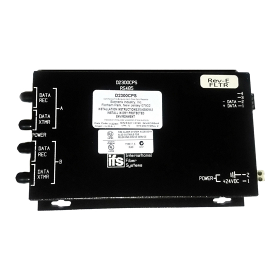
The Model D2300CPS from Siemens Building Tech-
nologies, Inc. (See Figure 1) is a Fiber Optic interface
for the MXL's RS-485 network (MNET or XNET) or
the FireFinder XLS network (HNET or XNET). It uses
a two-fiber (duplex) pair between each device. The
D2300CPS can function as either a repeater or an
end point unit.
DATA
REC
A
DATA
XTMR
POWER
DATA
REC
B
DATA
XTMR
WARNING: This module is NOT backwards
compatible with the existing 2300CP. This unit
uses +24VDC. Make sure to read the front of the
module and connect to the correct voltage.
Otherwise, serious damage to the unit will result.
Figure 1
D2300CPS Module
The D2300CPS can operate in either a daisy chain
(See Figure 2) or star configuration (See Figure 3).
This allows for network configurations that are not
possible with the RS-485 network alone.
WARNING:
The D2300CPS module is not listed for use by
Factory Mutual. Applications requiring fiber con-
nectivity of voice modules/systems are therefore
not Factory Mutual listed.
WARNING:
Do not use the D2300CPS with CXL Systems.
Siemens Building Technologies, Inc.
8 Fernwood Road
Florham Park, New Jersey 07932
P/N 315-050018-0
D2300CPS
(DO NOT USE) -4
RS485
(DO NOT USE) -3
- DATA -2
+ DATA -1
-2
POWER
-1
+24 VDC
MOUNTING
The D2300CPS has four keyhole slots for #6 screws.
Mount the device in the locations listed below using
the four #6 screws provided.
A bracket (P/N 500-692880) is available for mounting
the D2300CPS in any MXL enclosure that will accept
a MOM-4 (See Figure 4). This bracket has the same
footprint as the MOM-4 and accommodates two
D2300CPS modules. An assembly kit is included with
the bracket that contains four nuts and eight screws.
Mount the bracket in the enclosure with the four nuts
at the positions labeled X (See Figure 4). Start four of
the 6-32 screws and slip the keyhole slots in the
D2300CPS over them. Tighten the four screws.
System 3 style rails that mount on an MBR-2 or MME-3
backbox (P/N MSR-1) are also available and can be
used for mounting the D2300CPS with the System 3
MPFO Bracket. Up to three brackets can be installed on
a single rail.
A bracket, Model D2300-MP, is available for mounting
two D2300CPS modules in any FireFinder XLS CAB
enclosure. The D2300-MP fits in the same footprint as
a CC-5 and mounts to the CAB-MP. A hardware kit is
provided for attaching the D2300-MP to the CAB-MP
and mounting two D2300CPS modules onto the
D2300-MP. Mount the D2300CPS modules prior to
installing the D2300-MP onto the CAB-MP. Note that
when using two D2300CPS modules, the center two
mounting holes on each D2300CPS share the two
center studs on the D2300-MP (See Figure 5).
ELECTRICAL CONNECTIONS
POWER INPUT
The D2300CPS uses filtered or unfiltered 24 VDC.
The D2300CPS can only be powered from the
sources listed in Table 1 on page 6.
Siemens Building Technologies, Ltd.
2 Kenview Boulevard
Brampton, Ontario L6T 5E4 CN
Fire Safety
Advertisement

Related Manuals for Siemens D2300CPS


Summary of Contents for Siemens D2300CPS
- Page 1 INTRODUCTION MOUNTING The Model D2300CPS from Siemens Building Tech- The D2300CPS has four keyhole slots for #6 screws. nologies, Inc. (See Figure 1) is a Fiber Optic interface Mount the device in the locations listed below using for the MXL’s RS-485 network (MNET or XNET) or the four #6 screws provided.
- Page 2 -13 dB 62.5/125 FIBER -13 dB 62.5/125 FIBER - 9 dB 50/125 FIBER - 9 dB 50/125 FIBER SUPERVISED SUPERVISED CONNECTION CONNECTION D2300CPS D2300CPS D2300CPS EOLR EOLR EOLR 120 OHMS, 1/4W 120 OHMS, 1/4W 120 OHMS, 1/4W P/N 140-820150 P/N 140-820150...
- Page 3 DUPLEX OPTICAL FIBER POWER BUDGET - MAX LOSS -13 dB 62.5/125 FIBER SUPERVISED - 9 dB 50/125 FIBER TO ADDITIONAL D2300CPS MODULES CONNECTION CONNECTION CONNECTION D2300CPS D2300CPS D2300CPS RS-485 32 NODES MAX SUPERVISED PSR-1 EOLR USE THE 120 ¼ W, 5%...
- Page 4 P/N 500-692880 OMM-1 D2300CPS WARNING DISCONNECT POWER PRIOR TO REMOVING TERMINAL BLOCK PROTECTION Figure 4 Mounting the D2300CPS in an MBR-2 or MME-3 Backbox POWER LIMITED HNET/XNET FIBER OPTIC CABLE ROUTE AS SHOWN D2300-MP NIC-C RESET RESET POWER POWER PSC-12...
- Page 5 END POINT DATA N.C. DATA FACP N.C. XTMR Figure 6 Wiring the D2300CPS as both a Repeater and End Point Unit RS-485 RATINGS: USE THE 120 ¼ W, 5% 8V P-P EOL RESISTOR ASSEMBLY, AS APPLICABLE: 150mA MAX P/N 140-820150 (MMB-1/-2)
- Page 6 The following modules all draw current from the 24 VDC supply. Add the value for each module that is installed in the enclosure where the D2300CPS is to be installed. Be sure to include the D2300CPS in this calculation. c r i...
-
Page 7: Fiber Connections
D2300CPS is transmitting data on that FIBER CONNECTIONS channel. The yellow LED lights when data is received. The D2300CPS can function as both a repeater and an end point unit. When used as an end point, connect ELECTRICAL RATINGS to the fiber connectors labeled A. - Page 8 EOLR 120 OHMS, 1/4W (DO NOT USE) P/N 140-820150 (DO NOT USE) -DATA +DATA D2300CPS DO NOT USE SUPERVISED RS-485 RATINGS: 8V P-P 150mA MAX 80 OHMS MAX 18 AWG MIN NO EOLR REQUIRED AT THE NIC-C DO NOT USE...
-
Page 9: Technical Support
Contacting us For help installing, operating, maintaining, and troubleshooting this product, refer to this document and any other documentation provided. If you still have questions, contact us during business hours (Monday through Friday, excluding holidays, between 5 a.m. and 5 p.m. Pacific Time). Table 3. - Page 10 Copyright © 2011 UTC Fire & Security. All rights reserved. Trademarks and Interlogix and IFS names and logos are trademarks of patents UTC Fire & Security. Other trade names used in this document may be trademarks or registered trademarks of the manufacturers or vendors of the respective products.