Advertisement
Quick Links
Installation Instructions
Model D2300CPS
Multi Mode (850nm) Fiber Optic Interface
INTRODUCTION
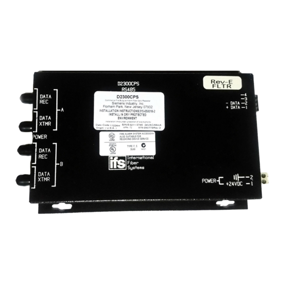
The Model D2300CPS from Siemens Industry, Inc. (See
Figure 1) is a Fiber Optic interface for the MXL's RS-485
network (MNET or XNET), FireFinder XLS/Desigo Fire
Safety Modular/Cerberus PRO Modular network
(HNET or XNET) or HUB-4 FSI. It uses a two-fiber
(duplex) pair between each device. The D2300CPS can
function as either a repeater or an end point unit.
D2300CPS
DATA
REC
A
DATA
XTMR
POWER
DATA
REC
B
DATA
XTMR
WARNING: This module is NOT backwards
compatible with the original 5V D2300CP. This
unit uses +24VDC. Make sure to read the front of
the module and connect to the correct voltage.
Otherwise, serious damage to the unit will result.
Figure 1
D2300CPS Module
The D2300CPS can operate in either a daisy chain
(See Figure 2) or star configuration (See Figure 3).
This allows for network configurations that are not
possible with the RS-485 network alone.
WARNING:
The D2300CPS module is not listed for use by
Factory Mutual. Applications requiring fiber con-
nectivity of voice modules/systems are therefore
not Factory Mutual listed.
WARNING:
Do not use the D2300CPS with CXL Systems.
Siemens Industry, Inc.
Building Technologies Division
Florham Park, NJ
P/N 315-050018-6
RS485
(DO NOT USE) -4
(DO NOT USE) -3
- DATA -2
+ DATA -1
-2
POWER
+24 VDC
-1
MOUNTING
The D2300CPS has four keyhole slots for #6 screws.
Mount the device in the locations listed below using
the four #6 screws provided.
A bracket (P/N 500-692880) is available for mounting
the D2300CPS in any MXL enclosure that will accept
a MOM-4 (See Figure 4). This bracket has the same
footprint as the MOM-4 and accommodates two
D2300CPS modules. An assembly kit is included with
the bracket that contains four nuts and eight screws.
Mount the bracket in the enclosure with the four nuts
at the positions labeled X (See Figure 4). Start four of
the 6-32 screws and slip the keyhole slots in the
D2300CPS over them. Tighten the four screws.
System 3 style rails that mount on an MBR-2 or MME-3
backbox (P/N MSR-1) are also available and can be
used for mounting the D2300CPS with the System 3
MPFO Bracket. Up to three brackets can be installed on
a single rail.
A bracket, Model D2300-MP, is available for mounting
two D2300CPS modules in any FireFinder XLS/
Desigo Fire Safety Modular/Cerberus PRO Modular
CAB enclosure. The D2300-MP fits in the same
footprint as a CC-5 and mounts to the CAB-MP. A
hardware kit is provided for attaching the D2300-MP to
the CAB-MP and mounting two D2300CPS modules
onto the D2300-MP. Mount the D2300CPS modules
prior to installing the D2300-MP onto the CAB-MP.
Note that when using two D2300CPS modules, the
center two mounting holes on each D2300CPS share
the two center studs on the D2300-MP (See Figure 5).
ELECTRICAL CONNECTIONS
POWER INPUT
The D2300CPS uses filtered or unfiltered 24 VDC.
The D2300CPS can only be powered from the
sources listed in Table 1 on page 6.
Siemens Canada, Ltd.
1577 North Service Road East
Oakville, Ontario
L6H 0H6 Canada
Advertisement

Related Manuals for Siemens D2300CPS


Summary of Contents for Siemens D2300CPS
-
Page 1: Installation Instructions
INTRODUCTION MOUNTING The Model D2300CPS from Siemens Industry, Inc. (See The D2300CPS has four keyhole slots for #6 screws. Figure 1) is a Fiber Optic interface for the MXL’s RS-485 Mount the device in the locations listed below using network (MNET or XNET), FireFinder XLS/Desigo Fire the four #6 screws provided. - Page 2 POWER BUDGET - MAX LOSS -8 dB 62.5/125 FIBER -8 dB 62.5/125 FIBER -6 dB 50/125 FIBER -6 dB 50/125 FIBER SUPERVISED SUPERVISED CONNECTION CONNECTION D2300CPS D2300CPS D2300CPS EOLR EOLR EOLR 120 OHMS, 1/4W 120 OHMS, 1/4W 120 OHMS, 1/4W P/N 140-820150 P/N 140-820150...
- Page 3 MULTI MODE DUPLEX OPTICAL FIBER POWER BUDGET - MAX LOSS -8 dB 62.5/125 FIBER SUPERVISED -6 dB 50/125 FIBER TO ADDITIONAL D2300CPS MODULES CONNECTION CONNECTION CONNECTION D2300CPS D2300CPS D2300CPS RS-485 32 NODES MAX SUPERVISED PSR-1 EOLR USE THE 120 ¼ W, 5%...
-
Page 4: Fiber Optic Cable
P/N 500-692880 OMM-1 D2300CPS WARNING DISCONNECT POWER PRIOR TO REMOVING TERMINAL BLOCK PROTECTION Figure 4 Mounting the D2300CPS in an MBR-2 or MME-3 Backbox POWER LIMITED HNET/XNET FIBER OPTIC CABLE ROUTE AS SHOWN D2300-MP NIC-C RESET RESET POWER POWER PSC-12... - Page 5 END POINT DATA N.C. DATA FACP N.C. XTMR Figure 6 Wiring the D2300CPS as both a Repeater and End Point Unit RS-485 RATINGS: USE THE 120 ¼ W, 5% 8V P-P EOL RESISTOR ASSEMBLY, 150mA MAX AS APPLICABLE: P/N 140-820150 (MMB-1/-2)
- Page 6 The following modules all draw current from the 24 VDC supply. Add the value for each module that is installed in the enclosure where the D2300CPS is to be installed. Be sure to include the D2300CPS in this calculation. t i u...
-
Page 7: Fiber Connections
The RS-485 MNET, XNET and HNET networks connect one D2300CPS and the receive data line (DATA to the D2300CPS on the terminal block with the mark- REC) on the other D2300CPS. ings +DATA (1) and -DATA(2). Terminals 3 and 4 are not used. - Page 8 EOLR 120 OHMS, 1/4W (DO NOT USE) P/N 140-820150 (DO NOT USE) -DATA +DATA D2300CPS DO NOT USE SUPERVISED RS-485 RATINGS: 8V P-P 150mA MAX 80 OHMS MAX 18 AWG MIN NO EOLR REQUIRED AT THE NIC-C DO NOT USE...
- Page 9 INTERFACE (DO NOT USE) P/N 140-820150 Port #2 x (DO NOT USE) -DATA +DATA PORT 1 PORT 2 SUPERVISED D2300CPS 20 FT IN CONDUIT RS-485 RATINGS: 8V P-P 150mA MAX 80 OHMS MAX 18 AWG MIN RS-485 MODEM OR RS-485...
- Page 10 Cyber security disclaimer Siemens products and solutions provide security functions to ensure the secure operation of building comfort, fire safety, security management and physical security systems. The security functions on these products and solutions are impor- tant components of a comprehensive security concept.