
Related Manuals for ABB HVC-R 107 V2


Summary of Contents for ABB HVC-R 107 V2
- Page 1 — EV CHARGING INFRASTRUCTURE User Manual (EU version) HVC-R 107/160 V2 E-Bus Charger Depot Box GEN2...
- Page 2 This document contains information about one or more ABB products and may include a description of or a reference to one or more standards that may be generally relevant to the ABB products. The presence of any such description of a standard or reference to a standard is not a representation that all the ABB products referenced in this document support all the features of the described or refer- enced standard.
-
Page 3: Table Of Contents
H V C - R 1 0 7 / 1 6 0 V 2 E -B U S C H A R G E R - U S E R M A N U A L Table of Contents Glossary ................................ 4 1 Introduction ............................. -
Page 4: Glossary
H V C - R 1 0 7 / 1 6 0 V 2 E -B U S C H A R G E R - U S E R M A N U A L Glossary Combined Charging System. A universal AC and DC charging system, also referred to as ‘Combo’. -
Page 5: Introduction
Introduction Preface The HVC-R product line is the new ABB solution for Overnight Charging of Heavy Vehicles. The prod- uct line allows 107kW and 160kW charging with up to 3 charging outlets per one charger. The charg- ing of the vehicles is done sequentially following the first come, first serve principle. -
Page 6: Owner Responsibilities
ABB’s warranty. Neither ABB nor its affiliates shall be liable to the purchaser of this product or third parties for dam- ages, losses, costs or expenses incurred by purchaser or third parties as a result of: an accident, mis- use or abuse of this product, or unauthorized modifications, repairs or alterations to this product, or failure to strictly comply ABB operating and maintenance instructions. -
Page 7: Safety Regulations
2. Contact the owner / site operator. 3. It is not permitted to operate the whole system if at least one of the Depot Charge Box Boxes GEN2 shows severe malfunction. Please contact ABB Service department for more information of error condition WARNING If there is an emergency 1. -
Page 8: Description Of The Product
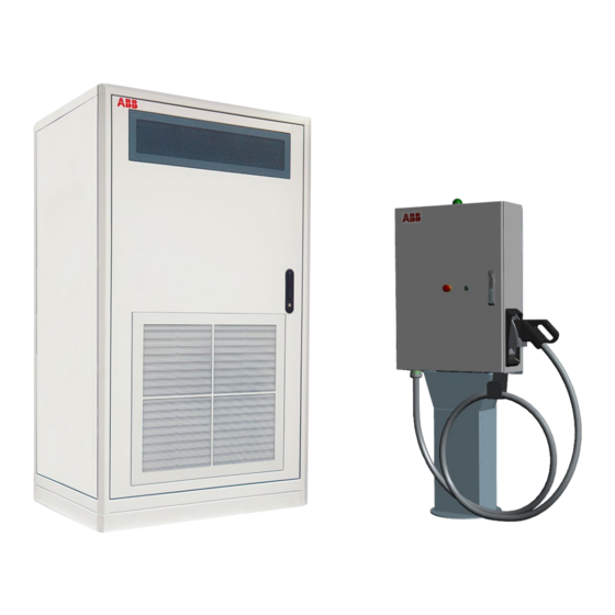
H V C - R 1 0 7 / 1 6 0 V 2 E -B U S C H A R G E R - U S E R M A N U A L Description of the product Overview of the system A. -
Page 9: Depot Charge Box Gen2
H V C - R 1 0 7 / 1 6 0 V 2 E -B U S C H A R G E R - U S E R M A N U A L Depot Charge Box GEN2 The user operated components are indicated on below: A. -
Page 10: Charger Configurations
H V C - R 1 0 7 / 1 6 0 V 2 E -B U S C H A R G E R - U S E R M A N U A L Charger configurations The charger is built up with a modular architecture. Supported charging standards in a charger configuration are described by a letter: Product Description... -
Page 11: Charging With 2, 3 Or 4 Depot Charge Boxes Gen2
H V C - R 1 0 7 / 1 6 0 V 2 E -B U S C H A R G E R - U S E R M A N U A L 4. The charger will automatically start to charge the vehicle after the preparation phase, and will indicate the progress by the LED state (see in figure 3). -
Page 12: Emergency Stop
H V C - R 1 0 7 / 1 6 0 V 2 E -B U S C H A R G E R - U S E R M A N U A L NOTICE Stop by emergency button The charger stops the charge session when the emergency stop is pushed. -
Page 13: Operator Instructions
The following points must be checked regularly: Internal RCDs and RCBOs need to be tested on correct functioning on a regular basis. During • the yearly maintenance round that is advised to be executed by a certified ABB technician, this will be checked. •... -
Page 14: Emergency Stop Inspection
In special cases the site operator with knowledge of the charger can be asked by ABB support to report about the status of some internal components of the charger. Therefore a brief description of the position and function of these components is described on the next pages. -
Page 15: Overview Of The Depot Charge Box Gen2
H V C - R 1 0 7 / 1 6 0 V 2 E -B U S C H A R G E R - U S E R M A N U A L 4.3.2 Overview of the Depot Charge Box GEN2 Front door Depot Charge Box GEN2 Door handle / lock (per Depot Charge Box GEN2 Unique system key) -
Page 16: Component Overview Depot Charge Box Gen2
H V C - R 1 0 7 / 1 6 0 V 2 E -B U S C H A R G E R - U S E R M A N U A L 4.3.4 Component overview Depot Charge Box GEN2 The main components as can be seen with an open front door: SPD (F4) AC Power Supply MCB (F5) AC Power Supply... -
Page 17: Switch The Depot Charge Box Gen2
H V C - R 1 0 7 / 1 6 0 V 2 E -B U S C H A R G E R - U S E R M A N U A L 2. Locate the main switch (A). 3. -
Page 18: Contact Information
Contact information NOTICE In case of problems Contact the site operator. ABB in your country Please contact ABB in your country for delivery and service information. ABB EV Infrastructure global ABB EV Infrastructure Address Heertjeslaan 6 2629 JG Delft The Netherlands... - Page 19 H V C - R 1 0 7 / 1 6 0 V 2 E -B U S C H A R G E R - U S E R M A N U A L Appendix: A. WEEE disposal – 2012-19/EU D O C U M E N T N O.
- Page 20 H V C - R 1 0 7 / 1 6 0 V 2 E -B U S C H A R G E R - U S E R M A N U A L NOTES D O C U M E N T N O. : 9 A K K 10 8 4 67 A 6 6 3 5 - E N V 0. 3 | D AT E : 2 0/ 1 2 / 2 0 2 2 PA G E 2 0 O F 2 0...