
Related Manuals for ABB HVC-R 100/150 V2


Summary of Contents for ABB HVC-R 100/150 V2
- Page 1 — INSTALL ATION GUIDE HVC-R 100/150 V2 E-Bus Charger Installation Guide for EU products Version 0.1...
- Page 2 In no event shall ABB be liable for direct, indirect, special, incidental or consequential damages of any nature or kind arising from the use of this document, nor shall ABB be liable for incidental or consequential damages arising from use of any software or hardware described in this document.
-
Page 3: Table Of Contents
HVC-R 100/150 V2 E-Bus Charger Installation Guide Table of Contents Introduction 1.1. Preface 1.2. Intended document users 1.3. Signs 1.4. Safety regulations 1.4.1. Owner responsibilities 1.4.2. Tilting and handling 1.4.3. Electric hazards 1.4.4. Installation safety 1.5. Environment and disposal of waste 1.6. - Page 4 HVC-R 100/150 V2 E-Bus Charger Installation Guide 4.2.2. Concrete foundation 4.2.3. Metal frame foundation 4.2.4. Mounting Power Cabinet directly on a floor 4.3. Mounting of the Dual Depot Charge Box 4.3.1. Available options 4.3.2. Concrete foundation for the pedestal 4.3.3.
- Page 5 HVC-R 100/150 V2 E-Bus Charger Installation Guide 5.12.1. Connecting the Pedestal to the Foundation 5.12.2. Mounting the Dual Depot Charge Box onto the Pedestal 5.13. Mounting the Dual Depot Charge Box onto a wall 5.13.1. Using the wall-mounting brackets 5.14. Cable connections of the Dual Depot Charge Box 5.14.1.
- Page 6 HVC-R 100/150 V2 E-Bus Charger Installation Guide Glossary Alternating Current. A computer network that interconnects computers systems within a limited area. Customer Acceptance Form. ABB Network Operating Centre; remotely CCS (Combo) checks the correct functioning of the Combined Charging System (also called charger.
-
Page 7: Introduction
This guide describes the planning and physical installation of the HVC-R 100/150 V2 E-Bus Charger at its location. The HVC-R 100/150 V2 E-Bus Charger is a DC fast charger system for hybrid or electrical buses that can be used for overnight charging which is based on the CCS Charging standard. -
Page 8: Safety Regulations
HVC-R 100/150 V2 E-Bus Charger Installation Guide WARNING Pinch Hazard Identifies a hazard that could result in injuries including the cases in which some body parts may be pinched or crushed. WARNING Fall Hazard Identifies a hazard that could result in injury due to unsafe work at height. -
Page 9: Tilting And Handling
Owner’s authority to operate the equipment and ABB’s warranty policy. Neither ABB nor its affiliates shall be liable to the purchaser of this product or third parties for damages, losses, costs or expenses borne by the Purchaser or third parties... -
Page 10: Electric Hazards
5. The installation and maintenance personnel must be supplied with their own lighting equipment, since the HVC-R 100/150 V2 E-Bus Charger has no lights inside the cabinet. 6. Always connect the Protective Earth (PE) first, before connecting the neutral (N) and Phase (P) wiring. -
Page 11: Environment And Disposal Of Waste
ABB Ltd and its affiliates are not liable for damages and/or losses related to such security breaches, any unauthorized access, interference, intrusion, leakage and/or theft of data or information. -
Page 12: Contact Information
HVC-R 100/150 V2 E-Bus Charger Installation Guide 1.7. Contact information ABB in your country Please contact ABB in your country for delivery and service information. ABB EV Infrastructure global ABB EV Infrastructure Address Heertjeslaan 6 2629 JG Delft The Netherlands... -
Page 13: Description Of The Product
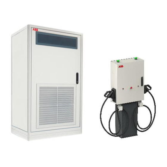
Electric hybrid and/or full electric Bus Parking space designated for Bus charging The HVC-R 100/150 V2 E-Bus Charger consists of multiple components and it may require additional elements depending on the project’s circumstances and location of installation which dictates whether these elements are needed. -
Page 14: Standard Hvc-R 100 V2 E-Bus Charger With One Dual Depot Charge Box
HVC-R 100/150 V2 E-Bus Charger Installation Guide 2.1.1. Standard HVC-R 100 V2 E-Bus Charger with one Dual Depot Charge Box The following parts are provided for this system configuration: 1x HVC-R 100 V2 Power Cabinet (ABB6AGC102603/ABB6AGC103332/ABB6AGC103337/ ABB6AGC103341) 1x Dual Depot Charge Box (ABB6AGC102131) 2.1.2. -
Page 15: Hvc Power Cabinet
HVC-R 100/150 V2 E-Bus Charger Installation Guide 2.1.5. HVC Power Cabinet Outside view of the HVC 100 /150 V2 Power Cabinet Overview of the closed Power Cabinet Base cover 3G Antenna Air outlet Air inlets (also on the left and back side) -
Page 16: Dual Depot Charge Box
HVC-R 100/150 V2 E-Bus Charger Installation Guide 2.1.6. Dual Depot Charge Box Outside view of the Dual Depot Charge Box Charge state indicator light 1 (beacon) Hanging bracket for charge cable 2 Door CCS DC plug and cable 2 Stop button 1... - Page 17 HVC-R 100/150 V2 E-Bus Charger Installation Guide Inside view of the Dual Depot Charge Box Communication connection Connection block Protection cover for DC contactors Document: v0.1 / Document No.: TBA | Date: XX-08-2021 Page 17 of 133...
-
Page 18: Accessories
HVC-R 100/150 V2 E-Bus Charger Installation Guide 2.2. Accessories The following parts can be ordered at the time of the initial order or afterwards. Contact ABB Sales department (see Contact information on Page 12 for contact details). 2.2.1. Foundation of Power Cabinet Concrete foundation The concrete foundation can be used to install the Power Cabinet on soil. -
Page 19: Pedestal Of The Dual Depot Charge Box
HVC-R 100/150 V2 E-Bus Charger Installation Guide 2.2.2. Pedestal of the Dual Depot Charge Box The pedestal can be used to attach the Dual Depot Charge Box in the open when it is not being mounted on a wall. Overview of Dual Depot Charge Box’s pedestal... -
Page 20: Foundation Of The Pedestal
HVC-R 100/150 V2 E-Bus Charger Installation Guide 2.2.3. Foundation of the pedestal The concrete foundation must be used to install the pedestal on soil. Overview of pedestal’s concrete foundation Cable conduit outputs Cable conduit inputs Amount Part number Description HVC-R concrete foundation Dual Depot Charge Box ABB6AGC103612 Document: v0.1 / Document No.: TBA | Date: XX-08-2021... -
Page 21: Wall-Mounting Brackets For Dual Depot Charge Box Safe Wall Fixing
The CAN/Ethernet communication between the Power Cabinet and Dual Depot Charge Boxes is achieved via an Ethernet cable. If the cable is not supplied by ABB, then gland dimensions listed in section Gland layout of the Dual Depot Charge Box on Page 91 must be followed. Please note that special precautions should be taken, so that pre-fabricated the cable could pass through the gland (for example order cable with M25 gland assembled on it). -
Page 22: Preparation
Diagram of the project’s phases A. Preparation The Owner / Site Operator has ordered an HVC-R 100/150 V2 E-Bus Charger. In this phase all preparation work must be completed before the Contractor can perform the civil and electrical works. See About preparation on Page 23. -
Page 23: About Preparation
The Contractor is responsible for all construction documentation of the site, i.a.: drawings, calculations, certifications, licenses and test reports. The location of the HVC-R 100/150 V2 E-Bus Charger must be selected. See section Location on Page 27 and section Geometry of infrastructure on Page 28. -
Page 24: Required Permits
Make sure the plan includes the possible occurrence of resulting delays. 3.3. Required permits The installation of an HVC-R 100/150 V2 E-Bus Charger will require a number of permits, depending on national and local laws. This section lists a number of points of attention. 3.3.1. Power connection The HVC Power Cabinet requires high current (400 V AC 238 A for 150 kW) connections. -
Page 25: Internet Access
Wireless, which requires coverage of a 3G network at the location. This is the preferred connection. A 3G modem with active SIM card is included with the HVC-R 100/150 V2 E-Bus Charger (a customer SIM card is not required). -
Page 26: Adapting The Grid
HVC-R 100/150 V2 E-Bus Charger Installation Guide 3.4. Adapting the grid The HVC 100 or 150 V2 Power Cabinet can be connected directly to the electrical grid or to an existing customer low voltage power distribution cabinet. In both cases a 170 A (for the... -
Page 27: Location
Do not install or use the HVC-R 100/150 V2 E-Bus Charger in areas where there is an explosion hazard. You must provide information about the HVC-R 100/150 V2 E-Bus Charger to the fire brigade. -
Page 28: Geometry Of Infrastructure
HVC-R 100/150 V2 E-Bus Charger Installation Guide 3.6. Geometry of infrastructure 3.6.1. Space required for the Power Cabinet A single HVC 100/150 V2 Power Cabinet requires a minimum space of 1170 x 2070 mm (W x D) or 1370 x 1970 mm (W x D). This space is calculated as follows: ... -
Page 29: Placement Of Multiple Power Cabinets
Maximum allowed pressure drop = 300 Pa. If the pressure drop of the room is higher than 300 Pa an extra fan should be placed. Contact ABB Sales department (see Contact information on Page 12 for contact details). 3.6.2. Placement of multiple Power Cabinets... -
Page 30: Space Required For The Dual Depot Charge Box
HVC-R 100/150 V2 E-Bus Charger Installation Guide 3.6.3. Space required for the Dual Depot Charge Box The Dual Depot Charge Box requires a minimum space of 1600 x 1150 mm (W x D). This space is calculated as follows: ... -
Page 31: Parking Space Arrangement
HVC-R 100/150 V2 E-Bus Charger Installation Guide 3.7. Parking space arrangement A site for EV charging can be designed in many different setups. This section is intended to give some useful information about the placement of a charger with respect to parking spaces and the different vehicle inlets for the charging cable. -
Page 32: Various Alignment Possibilities
HVC-R 100/150 V2 E-Bus Charger Installation Guide 3.7.2. Various alignment possibilities The charge inlets on a bus can be located on various positions. The most common buses have their inlets located at the front or the back of the vehicle, either on one of the sides or centrally (as indicated below). -
Page 33: Electrical Installation
HVC-R 100/150 V2 E-Bus Charger Installation Guide 3.8. Electrical installation The electrical installation must be completed according to the local safety and electrical regulations, and laws. See section Adapting the grid on Page 26 for the requirements of the electrical connection. A one-line diagram for the electrical connection for the Power Cabinet is shown in the figure below. - Page 34 HVC-R 100/150 V2 E-Bus Charger Installation Guide There are two additional options of connecting the AC auxiliary power supply for the Dual Depot Charge Boxes to the electrical grid. First option is an individual electrical connection for the Dual Depot Charge Box(es). The one line diagram is shown below.
-
Page 35: Civil Installation
Power Cabinet and the Dual Depot Charge Box are located below the ground. Depending on the location - e.g. If the HVC-R 100/150 V2 E-Bus Charger is located indoors, the cables can be led above the ground level. In this case the presence of cables trays is required to protect the cables. - Page 36 HVC-R 100/150 V2 E-Bus Charger Installation Guide Example of civil installation when the Dual Depot Charge Box is mounted on a wall Foundation of the Power Cabinet Wall on which the Dual Depot Charge Box will be mounted Flexible conduit for DC power cables...
-
Page 37: Lightning Protection
HVC-R 100/150 V2 E-Bus Charger Installation Guide 3.10. Lightning protection One electrode (ground rod) of maximum 10 Ω must be placed in to the earth near the foundation of the Power Cabinet. In some cases, additional grounding is required at the Dual Depot Charge Box’s side. -
Page 38: Construction
4. Construction 4.1. About construction The construction phase includes all works required to prepare the location and make it ready for the placement and connection of the HVC-R 100/150 V2 E-Bus Charger. The construction phase can start when: All engineering work is done. -
Page 39: Providing Foundation For The Power Cabinet
HVC-R 100/150 V2 E-Bus Charger Installation Guide 4.2. Providing foundation for the Power Cabinet 4.2.1. Available options Use the appropriate foundation for the type of surface that the Power Cabinet will be installed Soil Use a concrete foundation to get a firm fixation on soil. -
Page 40: Concrete Foundation
HVC-R 100/150 V2 E-Bus Charger Installation Guide 4.2.2. Concrete foundation WARNING Make sure that personnel cannot be crushed or become trapped while moving the foundation. Be aware that the weight of the concrete foundation is about 1300 kg. CAUTION Before you lower the foundation, remove sharp edges of the cable holes (B) in the foundation to protect the cables. - Page 41 HVC-R 100/150 V2 E-Bus Charger Installation Guide NOTICE This extra cable length is required to connect the AC power cable with the connectors in the Power Cabinet without problems. 11. Place both cover plates in the designated locations of the foundation.
-
Page 42: Metal Frame Foundation
HVC-R 100/150 V2 E-Bus Charger Installation Guide 4.2.3. Metal frame foundation Place the frame (A) in the desired position and mark the position of the holes for drilling. NOTICE The hole distance of 655mm on either side of the metal frame foundation is not equal to the hole distance (680 mm) from the HVC 150(S) cabinet. -
Page 43: Mounting Power Cabinet Directly On A Floor
HVC-R 100/150 V2 E-Bus Charger Installation Guide 4.2.4. Mounting Power Cabinet directly on a floor Drill and tap holes in the floor at the indicated locations (A). The holes must be suitable for bolts size M16. Make rectangular holes on the indicated locations (B) and (C). For detailed drawings of the bottom view of the Power Cabinet see Appendix A Dimensions of the Power Cabinet. -
Page 44: Mounting Of The Dual Depot Charge Box
HVC-R 100/150 V2 E-Bus Charger Installation Guide 4.3. Mounting of the Dual Depot Charge Box 4.3.1. Available options There are two options to install the Dual Depot Charge Box: Soil Use the concrete foundation to get a firm fixation on soil in combination with the pedestal. - Page 45 HVC-R 100/150 V2 E-Bus Charger Installation Guide 6. IMPORTANT: Place the foundation (A) in the correct position. Mind the desired location of the Dual Depot Charge Box’s door. 7. Make sure that the front top surface of the foundation is at least 15 mm above ground level (see figure above).
-
Page 46: Wall Mounting
HVC-R 100/150 V2 E-Bus Charger Installation Guide 4.3.3. Wall mounting Prerequisites: Tools: mark tools, level tool, drilling machine, drill bit (Ø10 mm or Ø7.5 mm), 4x wall plugs (Ø10 mm, L = 50 mm) NOTICE The Dual Depot Charge Box must be mounted levelly in order to work properly. -
Page 47: Cable Routing
HVC-R 100/150 V2 E-Bus Charger Installation Guide In case of a concrete or stone wall, insert wall-plugs (4x) into the holes. NOTICE The activities regarding the installation of cable ducts, that are to contain the cables connecting the Dual Depot Charge Box, are entirely dependent on the installation location and may differ between specific locations. - Page 48 HVC-R 100/150 V2 E-Bus Charger Installation Guide Overview of electrical connections of a charge system with two Dual Depot Charge Boxes supplied with AC power from Power Cabinet Overview of electrical connections of a charge system with two Dual Depot Charge Boxes supplied with AC power from distribution board Document: v0.1 / Document No.: TBA | Date: XX-08-2021...
-
Page 49: Ac Power Cable
HVC-R 100/150 V2 E-Bus Charger Installation Guide 4.4.2. AC power cable For the Power Cabinet: Cable type: 3P+PE (optional shielded). The cable shielding (if present) must be attached to the PE Rail at both ends of the cable. -
Page 50: Grounding Of The Dual Depot Charge Box
HVC-R 100/150 V2 E-Bus Charger Installation Guide 4.4.5. Grounding of the Dual Depot Charge Box PE must be connected to each of the Dual Depot Charge Boxes by 35 mm cable as described in the IEC 61851-23. Grounding scheme is dependent on the layout of the specific installation site and contracted electrical company should define detailed design of grounding installation. -
Page 51: Optional External Interface Cables
HVC-R 100/150 V2 E-Bus Charger Installation Guide 4.4.6. Optional external interface cables There is a possibility to connect an external Beacon light, stop button and/or Emergency stop button (EMO) to the Dual Depot Charge Box. Optional external interface Requirements Beacon light... -
Page 52: Cable Specification List
HVC-R 100/150 V2 E-Bus Charger Installation Guide 4.4.7. Cable specification list Tables below provide general specifications of the required cables. Use these tables to select cables, taking into account local installation environment, cable length, cable temperature rating, losses and local regulations. -
Page 53: Internet Connection
In most cases the integrated 3G modem is used for wireless internet access. A customer SIM card is not required. If there is no 3G signal available, a standard wired internet connection is required. For this option, contact ABB Sales department (see Contact information on Page 12 for contact details). -
Page 54: Placement And Connection
HVC-R 100/150 V2 E-Bus Charger Installation Guide 5. Placement and Connection 5.1. About placement and connection When the construction phase is finished, the HVC-R 100/150 E-Bus Charger can be placed and connected. The planning steps for the placement and connection phase are shown in the figure below. -
Page 55: Routing The Cables
HVC-R 100/150 V2 E-Bus Charger Installation Guide 5.2. Routing the cables Unpack the cables. See Cable routing on Page 47 for details on which cables are needed. Removing the foundation’s cover plates Remove the top cover plate (B) and the front cover plate (C) from the foundation (A) by loosening the bolts (D). -
Page 56: Unpacking Power Cabinet
HVC-R 100/150 V2 E-Bus Charger Installation Guide 5.3. Unpacking Power Cabinet 5.3.1. Before unpacking NOTICE Unloading Power Cabinet The delivery truck only unloads the pallet carrying the Power Cabinet. The delivery truck will not move the Power Cabinet to its final location. -
Page 57: Remove Packaging
HVC-R 100/150 V2 E-Bus Charger Installation Guide 5.3.2. Remove packaging Prerequisites Tools: spanner (size 24). Unpacking of the Power Cabinet Remove the packaging material from the Power Cabinet. Remove the bag which contains the keys, cover caps and mounting material that are attached with tape on one of the lifting eyebolts at the top of the cabinet. -
Page 58: Moving The Power Cabinet
HVC-R 100/150 V2 E-Bus Charger Installation Guide 5.4. Moving the Power Cabinet There are two options to move the Power Cabinet from the delivery truck to the location. Use a hoist to lift the cabinet from the top. See Moving the Power Cabinet with a hoist on Page 59. -
Page 59: Moving The Power Cabinet With A Hoist
HVC-R 100/150 V2 E-Bus Charger Installation Guide 5.4.1. Moving the Power Cabinet with a hoist Moving Power Cabinet with a hoist Swivel eye bolts (standard delivered with the cabinet) Lifting loops Hoisting equipment Prerequisites: A minimum of two qualified workers are required: one person to operate the hoisting equipment, the other to guide the Power Cabinet to its location. -
Page 60: Moving The Power Cabinet With A Forklift Truck
HVC-R 100/150 V2 E-Bus Charger Installation Guide 5.4.2. Moving the Power Cabinet with a forklift truck Moving Power Cabinet with a forklift Prerequisites: A minimum of two qualified workers are required: one person to operate the forklift truck, the other to guide the Power Cabinet to its location. -
Page 61: Installing The Power Cabinet Onto A Foundation
HVC-R 100/150 V2 E-Bus Charger Installation Guide 5.5. Installing the Power Cabinet onto a foundation 5.5.1. Connecting Power Cabinet to a foundation Prerequisites: Tools: spanner (size 24). Cover caps (4x) that were removed from the Power Cabinet (bag with parts). - Page 62 HVC-R 100/150 V2 E-Bus Charger Installation Guide Placing the Power Cabinet on metal frame foundation Foundation Power Cabinet Cables Tapped holes Carefully lower the Power Cabinet (B) onto the foundation (A). Make sure that you do not trap the cables (C).
-
Page 63: Opening The Door Of The Power Cabinet
HVC-R 100/150 V2 E-Bus Charger Installation Guide Tighten the bolts with a tightening torque of 200 Nm. Removing swivel eye bolts Remove the swivel eye bolts or lifting loops (A). Place the cover caps (B) in the holes (4x). 5.5.2. Opening the door of the Power Cabinet Prerequisites: ... -
Page 64: Loosening The Sliding Plate Of The Guidance Plates
HVC-R 100/150 V2 E-Bus Charger Installation Guide 5.5.3. Loosening the sliding plate of the guidance plates Prerequisites: Tools: spanner (size 13). Loosen the bolts (A). Move the sliding plate (B) of the 2 guidance plates. 5.5.4. Routing cables through the guidance plates The method of routing cables through the Power Cabinet’s floor... -
Page 65: Tightening Sliding Plates Of The Guidance Plates
HVC-R 100/150 V2 E-Bus Charger Installation Guide NOTICE A minimum length of 3000 mm is required, as the cable connectors are located in the middle of the Power Cabinet. 5.5.5. Tightening sliding plates of the guidance plates Prerequisites: Tools: spanner (size 13). -
Page 66: Installing Border Covers Of The Power Cabinet
HVC-R 100/150 V2 E-Bus Charger Installation Guide 5.5.6. Installing border covers of the Power Cabinet NOTICE Only applicable when the Power Cabinet is placed on a concrete foundation. Prerequisites: Tools: torx screwdriver (size 2163TX-T30). M5 bolts (8x) previously removed from the Power Cabinet (bag containing parts). -
Page 67: Installing Border Covers Of The Metal Frame Foundation
HVC-R 100/150 V2 E-Bus Charger Installation Guide 5.5.7. Installing border covers of the metal frame foundation NOTICE Only applicable when the Power Cabinet is placed on a metal frame foundation. The supplied front and rear cover on the Power Cabinet are not to be used in this case. -
Page 68: Installing Front Cover Plate On The Foundation
HVC-R 100/150 V2 E-Bus Charger Installation Guide 5.5.8. Installing front cover plate on the foundation NOTICE Only applicable when the Power Cabinet is placed on a concrete foundation. Prerequisites: Tools: spanner (size 19) Attaching cover plate to the concrete foundation Place the front cover plate (B) on the foundation (A). -
Page 69: Connecting Ac Power Cables And Pe Wires To The Power Cabinet
HVC-R 100/150 V2 E-Bus Charger Installation Guide 5.6. Connecting AC power cables and PE wires to the Power Cabinet 5.6.1. Removing the protection covers Prerequisites: Tools: cross-head screwdriver Removing the protection plate Remove the protection plate (A) by loosening the screws (B). -
Page 70: Connecting The Pe Wire Of The Ac Power Cables
HVC-R 100/150 V2 E-Bus Charger Installation Guide 5.6.2. Connecting the PE wire of the AC power cables Prerequisites: Tools: wire cutter, wire stripper pliers, wire-end ring, spanner (size 19), torque wrench (size 19). DANGER Make sure that the main switch of the power supply group for the product is set to the OFF position. -
Page 71: Connecting The Ac Power Cables
HVC-R 100/150 V2 E-Bus Charger Installation Guide 5.6.3. Connecting the AC power cables Prerequisites: Tools: wire cutter, wire stripper pliers, spanner (size 19), torque wrench (size 19). DANGER Make sure that the main switch of the power supply group for the product is set to the OFF position. -
Page 72: Installing The Protection Covers
HVC-R 100/150 V2 E-Bus Charger Installation Guide 5.6.4. Installing the protection covers Prerequisites: Tools: cross-head screwdriver Attaching protection covers to the connector block Take the 3 protection covers (previously removed in Removing the protection covers on Page 69). Place the protection covers (D) back on the connector blocks (C). -
Page 73: Installing Lightning Protection (Optional)
Leave the main switch OFF. The Power Cabinet is not ready to use yet. If there is no appointment for commissioning yet, contact the ABB Delivery department to make an appointment for commissioning. See Contact information on Page 12 for contact details. -
Page 74: Attaching Pe Wire Connecting The Dual Depot Charge Box
HVC-R 100/150 V2 E-Bus Charger Installation Guide 5.6.6. Attaching PE wire connecting the Dual Depot Charge Box Prerequisites: Tools: wire cutter, wire stripper pliers, wire-end ring, spanner (size 19), torque wrench (size 19). Method of connecting the PE wire connecting the Dual Depot Charge Box Cut the PE wire of the power cable to the proper length to reach the PE rail. -
Page 75: Connecting The Power Cabinet's Dc Power Cables
HVC-R 100/150 V2 E-Bus Charger Installation Guide 5.7. Connecting the Power Cabinet’s DC power cables Prerequisites: Tools: wire cutter, wire stripper pliers, cable lugs (6x), spanner (size 19), torque wrench (size 19), cross-head screwdriver. DANGER Make sure that the main switch of the power supply group for the product is set to the OFF position. -
Page 76: Connecting The Dc Power Cables
HVC-R 100/150 V2 E-Bus Charger Installation Guide 5.7.2. Connecting the DC power cables Method of connecting the DC power cables Cut the wires of the DC power cable to the proper lengths to reach the connectors. Do not make the wire routing neither too tight nor too loose. -
Page 77: Installing The Protection Cover
HVC-R 100/150 V2 E-Bus Charger Installation Guide 5.7.3. Installing the protection cover Attaching the protection cover Take the protection plate (previously removed in Removing the protection cover on Page 75). Place the protection plate (A) back over the DC connector blocks and secure the plate by the screws (B) (4x). -
Page 78: Connecting Interlock Cable To The Power Cabinet
HVC-R 100/150 V2 E-Bus Charger Installation Guide 5.8. Connecting Interlock cable to the Power Cabinet Prerequisites: Tools: wire cutter, wire stripper pliers, screwdriver, ferrules, crimp pliers. DANGER Make sure that the main switch of the power supply group for the product is set to the OFF position. - Page 79 HVC-R 100/150 V2 E-Bus Charger Installation Guide Location of required terminal blocks Terminal block Interlock cable Move the cable towards the terminal block (A). Strip 11 mm of the insulation from the ends of the White and Brown wires only! Crimp a ferrule onto the ends of the White and Brown wires.
-
Page 80: Connecting The Communication Cable To The Power Cabinet
HVC-R 100/150 V2 E-Bus Charger Installation Guide 5.9. Connecting the communication cable to the Power Cabinet Prerequisites: Tools: ty-raps 5.9.1. Routing the cable to the terminal blocks Preferred cable route Route the communication fiber cable to module D1 (B) and D2 (A). Refer to the figure for the preferred cable route inside the cabinet. -
Page 81: Connecting The Ethernet Cable To The Power Cabinet
HVC-R 100/150 V2 E-Bus Charger Installation Guide 5.9.2. Connecting the Ethernet cable to the Power Cabinet Location of the CAN2ETH board 1. Route the Ethernet communication cable (A) to the CAN2ETH board (B). 2. Connect the RJ45 plug to the terminal J1 (C). -
Page 82: Closing The Door Of The Power Cabinet
HVC-R 100/150 V2 E-Bus Charger Installation Guide 5.10. Closing the door of the Power Cabinet Closing the Power Cabinet’s door Prerequisites: The key previously removed from the Power Cabinet Close the door (A). Lock the handle (B). Document: v0.1 / Document No.: TBA | Date: XX-08-2021... -
Page 83: Unpacking The Dual Depot Charge Box
HVC-R 100/150 V2 E-Bus Charger Installation Guide 5.11. Unpacking the Dual Depot Charge Box 5.11.1. Before unpacking CAUTION Do not pollute the environment with plastic and cardboard packaging. Dispose of the packaging elements according the regionally applicable regulations regarding the environment. -
Page 84: Installing The Dual Depot Charge Box Onto A Pedestal
To prevent damage to the paint layer of the pedestal, always place the pedestal on a secure surface that provides sufficient protection against scratches and other damage. ABB is not responsible for any damage caused to the pedestal during its unpacking. 10. Remove all protective foam from the pedestal. - Page 85 HVC-R 100/150 V2 E-Bus Charger Installation Guide Removing the pedestal’s rear cover plate. 5. Carefully position the Pedestal (B) next to the foundation (D). 6. Pull the cables (E) through the opening (F). Indication of the way the pedestal should be place on the foundation.
- Page 86 HVC-R 100/150 V2 E-Bus Charger Installation Guide 7. Erect the Pedestal (B). NOTICE This must be carried out by two people, one of whom will tilt the pedestal on one of the sides. Method of connecting the pedestal to the concrete foundation 8.
-
Page 87: Mounting The Dual Depot Charge Box Onto The Pedestal
HVC-R 100/150 V2 E-Bus Charger Installation Guide 5.12.2. Mounting the Dual Depot Charge Box onto the Pedestal Prerequisites: All packaging material is removed from the Pedestal. A minimum of two people is required. Tools: torx screwdriver (size TT20). -
Page 88: Mounting The Dual Depot Charge Box Onto A Wall
HVC-R 100/150 V2 E-Bus Charger Installation Guide 5.13. Mounting the Dual Depot Charge Box onto a wall Prerequisites: All packaging material is removed from the Dual Depot Charge Box. A minimum of two people is required. Tools: spanner (size 13). -
Page 89: Using The Wall-Mounting Brackets
HVC-R 100/150 V2 E-Bus Charger Installation Guide 5.13.1. Using the wall-mounting brackets NOTICE Make sure that the wall, onto which the Dual Depot Charge Box is to be installed, will support the weight of the device. The Dual Depot Charge Box can be easily mounted by using the wall-mounting brackets, see Wall-mounting brackets for Dual Depot Charge Box safe wall fixing on Page 21. - Page 90 HVC-R 100/150 V2 E-Bus Charger Installation Guide Mounting the Dual Depot Charge Box onto a wall Document: v0.1 / Document No.: TBA | Date: XX-08-2021 Page 90 of 133...
-
Page 91: Cable Connections Of The Dual Depot Charge Box
HVC-R 100/150 V2 E-Bus Charger Installation Guide 5.14. Cable connections of the Dual Depot Charge Box DANGER Make sure that the main switch of the power supply group for the product is set to the OFF position. Do a voltage check to make sure that the electrical power is disconnected from the system. -
Page 92: Opening The Door Of The Dual Depot Charge Box
HVC-R 100/150 V2 E-Bus Charger Installation Guide 5.14.2. Opening the door of the Dual Depot Charge Box Prerequisites The key previously removed from the Dual Depot Charge Box. Opening the door of the Dual Depot charge Box Unlock the handle (B). - Page 93 HVC-R 100/150 V2 E-Bus Charger Installation Guide 2. Mind the cables connected to the fans. They must be unplugged before moving the cover plate. 3. Put the protection plate (A), the screws and the washers (B) in a safe location as it will be installed back later on.
-
Page 94: Connect The External Pe Wire
HVC-R 100/150 V2 E-Bus Charger Installation Guide WARNING In case the Pedestal is used, the PE wire from the Power Cabinet must be connected first to the GND point of the Pedestal. See Install lighting protection (optional) on Page 95. -
Page 95: Install Lighting Protection (Optional)
HVC-R 100/150 V2 E-Bus Charger Installation Guide 5.14.5. Install lighting protection (optional) NOTICE When using this option, the PE wire between the Power Cabinet and the Dual Depot Charge Box doesn’t have to be installed. For more details see section Cables connecting the Dual Depot Charge Boxes ... -
Page 96: Connecting The Pe Or Lighting Protection Wire Onto The Pedestal
HVC-R 100/150 V2 E-Bus Charger Installation Guide 5.14.6. Connecting the PE or lighting protection wire onto the pedestal Prerequisites: Tools: wire cutter, wire stripper pliers, cable lugs (2x), spanner (size 13), torque wrench (size 13). Instructions on connecting PE or lightning protection wire to the pedestal. - Page 97 HVC-R 100/150 V2 E-Bus Charger Installation Guide 1. Make a loop on the PE wire that is coming from the Power Cabinet or ground electrode (F). 2. Cut the PE wire from the Power Cabinet or ground electrode to the correct length - allowing to reach the GND point on the pedestal (I).
-
Page 98: Connecting The Dc Power In- And Output Cables
HVC-R 100/150 V2 E-Bus Charger Installation Guide 5.14.7. Connecting the DC power in- and output cables Prerequisites: Tools: wire cutter, wire stripper pliers, cable lugs, spanner (size 17), torque wrench (size 17). WARNING It is not allowed to remove the connector plates (I - in the picture below), nor to loosen their mountings. - Page 99 HVC-R 100/150 V2 E-Bus Charger Installation Guide Connection of the DC inputs: 1. Loosen and remove the cable gland’s (#05 and #07) nuts for the DC power input cables. 2. Slide the cable gland’s nuts over the DC power cables.
- Page 100 HVC-R 100/150 V2 E-Bus Charger Installation Guide NOTICE The connections presented below should be executed by leading the required cables through the conduit (A) located behind the connections bars (B). Utilize tie wraps to attach the cables to the holders (C).
-
Page 101: Connecting The Ac Auxiliary Power Cable
HVC-R 100/150 V2 E-Bus Charger Installation Guide 5.14.8. Connecting the AC auxiliary power cable Prerequisites: Tools: wire cutter, wire stripper pliers, ferrule, crimp pliers, screwdriver Instructions on preparing the wires and location of required terminal blocks. Location of terminal blocks X4 and the preferred cable route. -
Page 102: Connecting The Interlock Cable From The Power Cabinet Or The Dual Depot Charge Box
HVC-R 100/150 V2 E-Bus Charger Installation Guide 5.14.9. Connecting the InterLock cable from the Power Cabinet or the Dual Depot Charge Box Prerequisites: Tools: wire cutter, wire stripper pliers, screwdriver, ferrules, crimp pliers Location of terminal blocks X3 and the preferred cable route. -
Page 103: Connecting The Interlock Cable To The Next Dual Depot Charge Box
HVC-R 100/150 V2 E-Bus Charger Installation Guide Functional description Connector Wire color Interlock In (*) X3-2 White Interlock Out (**) X3-3 Brown DC Guard A X3-6 Green DC Guard A GND X3-7 Yellow Interlock GND X3-1 Shield (*) Interlock Out in Power Cabinet. -
Page 104: Connecting The Communication Ethernet Cable (Input)
HVC-R 100/150 V2 E-Bus Charger Installation Guide 4. Shorten the InterLock cable to the correct length – allowing to reach the terminal block X4. Do not make the cable routing too tight, or too loose. 5. Tighten the nut of the gland to secure the InterLock cable. -
Page 105: Connecting The Communication Ethernet Cable (Output)
HVC-R 100/150 V2 E-Bus Charger Installation Guide 5.14.12. Connecting the communication Ethernet cable (output) Information in this chapter refers to the communication cables connecting the Dual Depot Charge Box to the next Dual Depot Charge Box. 1. Loosen and remove the cable gland’s (#16) nut for the communication Ethernet cable. -
Page 106: Connecting External Emo, Beacon And Stop Button Cables (Optional)
HVC-R 100/150 V2 E-Bus Charger Installation Guide 5.14.13. Connecting external EMO, Beacon and Stop button cables (optional) NOTICE There is a possibility to connect an external Beacon light, Stop button and/or Emergency Stop Button(s) (EMO) to the Dual Depot Charge Box,... - Page 107 HVC-R 100/150 V2 E-Bus Charger Installation Guide The cable connections for external devices mentioned in this chapter should be led through glands #09 and/or #10. It is recommended leading all the necessary external device cables through the glands simultaneously, as up to three cables may pass through a gland.
- Page 108 HVC-R 100/150 V2 E-Bus Charger Installation Guide External Stop Button: It is possible to connect an external stop button for each of the charge lines. 1. Loosen and remove the cable gland’s (#09 or #10) nut for the Ext. Beacon cable.
-
Page 109: Installing The Protection Cover
HVC-R 100/150 V2 E-Bus Charger Installation Guide 5.14.14. Installing the protection cover Prerequisites: Tools: cross-head screwdriver Mounting the protection cover Attaching the protection cover with screws 1. Take the protection cover, the screws and the washers that were previously removed in Removing the protection cover on Page 75. -
Page 110: Closing The Door Of The Dual Depot Charge Box
HVC-R 100/150 V2 E-Bus Charger Installation Guide 5.14.15. Closing the door of the Dual Depot Charge Box Prerequisites The key previously removed from the Dual Depot Charge Box Closing the door of the Dual Depot Charge Box Close the door (A). -
Page 111: Reattaching Rear Cover Plate Of The Pedestal
HVC-R 100/150 V2 E-Bus Charger Installation Guide 5.14.16. Reattaching rear cover plate of the Pedestal Prerequisites: Tools: torx screwdriver (size T30), wire cutter, wire stripper pliers, cable lugs (2x), spanner (size 10), torque wrench (size 10). Reattaching the pedestal’s rear cover plate Overview of the pedestal after reattaching the rear cover plate Document: v0.1 / Document No.: TBA | Date: XX-08-2021... - Page 112 HVC-R 100/150 V2 E-Bus Charger Installation Guide Instructions on preparing and connecting the PE wire 1. Place the front cover plate (B) against the back side of the Pedestal (A). 2. Insert the M6 bolts (C) into the holes (6x) and tighten them.
-
Page 113: Reattaching Front Cover Plate Of The Pedestal
HVC-R 100/150 V2 E-Bus Charger Installation Guide 5.14.17. Reattaching front cover plate of the Pedestal Prerequisites: Tools: torx screwdriver (size T30), wire cutter, wire stripper pliers, cable lugs (2x), spanner (size 10), torque wrench (size 10). Reattaching the pedestal’s front cover plate Overview of the front cover plate’s connection from inside the pedestal... - Page 114 HVC-R 100/150 V2 E-Bus Charger Installation Guide Instructions on preparing and connecting the PE wire 1. It is necessary to connect the cover plate and the pedestal with a PE wire. Prepare a wire of appropriate length – no longer than allowing to open the rear cover plate.
-
Page 115: Commissioning
Commissioning The commissioning of the HVC-R 100/150 E-Bus Charger needs to be performed by a service engineer from the ABB Delivery department and/or a certified local ABB service engineer. Both will need the support from the local Contractor. Before the service engineer can begin, the following conditions must be met: ... -
Page 116: Customer Acceptance Form (Caf)
A list of remaining items. Once the CAF is signed, the customer support will be handled by the ABB Service department. If there are any remaining items, they can be listed on the CAF document, together with the agreed solution and the expected date of completion. -
Page 117: Service And Maintenance
HVC-R 100/150 V2 E-Bus Charger Installation Guide 7. Service and Maintenance 7.1. About Service and Maintenance Indication of Service and Maintenance phase on the planning diagram Service and Maintenance Maintenance is done according to the maintenance schedule, which is outside of the scope of this document. - Page 118 HVC-R 100/150 V2 E-Bus Charger Installation Guide NOTICE If the HVC-R 100/150 E-Bus Charger is exposed to rain, it is sufficient to clean it twice a year. CAUTION Do not use high-pressure water jets. Water may leak into the Power Cabinet.
-
Page 119: Technical Specification
HVC-R 100/150 V2 E-Bus Charger Installation Guide 8. Technical specification 8.1. Electrical specification od a complete 107 kW system AC Input Power Cabinet Supply voltage 3-phase, 400 V AC: PE, L1, L2, L3 Input voltage range 400 V AC ± 10% Input frequency range 50 Hz ±... -
Page 120: Electrical Specification Of A Complete 160 Kw System
HVC-R 100/150 V2 E-Bus Charger Installation Guide 8.2. Electrical specification of a complete 160 kW system AC Input Power Cabinet Supply voltage 3-phase, 400 V AC: PE, L1, L2, L3 Input voltage range 400 V AC ± 10% Input frequency range 50 Hz ±... -
Page 121: Environment
HVC-R 100/150 V2 E-Bus Charger Installation Guide 8.4. Environment Environment specification Power Cabinet Ingression protection IP54 Temperature range – Operation -35 ºC to +45 ⁰C Temperature range – Storage -10 ºC to +70 ⁰C Humidity 5 % to 95 %, RH – non-condensing... -
Page 122: Appendices
HVC-R 100/150 V2 E-Bus Charger Installation Guide 9. Appendices Dimensions of the Power Cabinet Dimensions of the Dual Depot Charge Box Dimensions of the Power Cabinet’s Concrete Foundation Dimensions of the Power Cabinet’s Metal Foundation Power Cabinet – Outline with the Foundation... -
Page 123: A Dimensions Of The Power Cabinet
HVC-R 100/150 V2 E-Bus Charger Installation Guide A. Dimensions of the Power Cabinet Document: v0.1 / Document No.: TBA | Date: XX-08-2021 Page 123 of 133... - Page 124 HVC-R 100/150 V2 E-Bus Charger Installation Guide Document: v0.1 / Document No.: TBA | Date: XX-08-2021 Page 124 of 133...
-
Page 125: B Dimensions Of The Dual Depot Charge Box
HVC-R 100/150 V2 E-Bus Charger Installation Guide B. Dimensions of the Dual Depot Charge Box Document: v0.1 / Document No.: TBA | Date: XX-08-2021 Page 125 of 133... -
Page 126: C Dimensions Of The Power Cabinet's Concrete Foundation
HVC-R 100/150 V2 E-Bus Charger Installation Guide C. Dimensions of the Power Cabinet’s Concrete Foundation Document: v0.1 / Document No.: TBA | Date: XX-08-2021 Page 126 of 133... - Page 127 HVC-R 100/150 V2 E-Bus Charger Installation Guide Document: v0.1 / Document No.: TBA | Date: XX-08-2021 Page 127 of 133...
-
Page 128: D Dimensions Of The Power Cabinet's Metal Foundation
HVC-R 100/150 V2 E-Bus Charger Installation Guide D. Dimensions of the Power Cabinet’s Metal Foundation Document: v0.1 / Document No.: TBA | Date: XX-08-2021 Page 128 of 133... -
Page 129: E Power Cabinet - Outline With The Foundation
HVC-R 100/150 V2 E-Bus Charger Installation Guide E. Power Cabinet – Outline with the Foundation Document: v0.1 / Document No.: TBA | Date: XX-08-2021 Page 129 of 133... -
Page 130: F Signal Connection Diagram
HVC-R 100/150 V2 E-Bus Charger Installation Guide F. Signal connection diagram Document: v0.1 / Document No.: TBA | Date: XX-08-2021 Page 130 of 133... -
Page 131: G Ground Overview Of The System
HVC-R 100/150 V2 E-Bus Charger Installation Guide G. Ground overview of the system Document: v0.1 / Document No.: TBA | Date: XX-08-2021 Page 131 of 133... -
Page 132: Hweee Disposal - 2012-19/Eu
HVC-R 100/150 V2 E-Bus Charger Installation Guide H. WEEE disposal – 2012-19/EU Document: v0.1 / Document No.: TBA | Date: XX-08-2021 Page 132 of 133... - Page 133 HVC-R 100/150 V2 E-Bus Charger Installation Guide NOTES Document: v0.1 / Document No.: TBA | Date: XX-08-2021 Page 133 of 133...