Hitachi C 10FSH Instruction Manual
Slide compound miter saw
Hide thumbs
Also See for C 10FSH:
- Safety instructions and instruction manual (96 pages) ,
- Handling instructions manual (64 pages) ,
- Technical data and service manual (97 pages)
Table of Contents

Related Manuals for Hitachi C 10FSH


Summary of Contents for Hitachi C 10FSH
- Page 1 Slide Compound Miter Saw Ingletadora telescopica C 10FSH C 10FSB • Read through carefully and understand these instructions before use. Leer cuidadosamente y comprender estas instrucciones antes del uso. Handling instructions Instrucciones de manejo...
-
Page 2: Table Of Contents
CONTENTS English PAGE PAGE IMPORTANT SAFETY INFORMATION ..... 3 APPLICATIONS ............10 MEANINGS OF SIGNAL WORDS ......3 PREPARATION BEFORE OPERATION ....11 SAFETY ................3 BEFORE USING ............12 IMPORTANT SAFETY INSTRUCTIONS FOR BEFORE CUTTING ............. 13 USING ALL POWER TOOLS ........3 PRACTICAL APPLICATIONS ........ -
Page 3: Important Safety Information
Hazards that must be avoided to prevent bodily injury or machine damage are identified by WARNINGS on the power tool and in this Instruction Manual. NEVER use this power tool in a manner that has not been specifically recommended by HITACHI. MEANINGS OF SIGNAL WORDS... - Page 4 English 9. ALWAYS USE EYE PROTECTION WHEN WORKING WITH THE TOOL TO PREVENT EYE INJURY. Ordinary eyeglasses do not provide adequate protection because the lenses are not made of safety glass. Also, use a face mask for additional safety and wear a dust mask if the cutting operation produces dust.
- Page 5 English Always wear snug-fitting clothing, non-skid footwear (preferably with steel toes) and eye protection when operating the POWER TOOL. Always handle the POWER TOOL carefully. If the POWER TOOL falls or strikes against a hard object, it might become deformed or cracked or sustain other damage. Always cease operating the saw at once, if you notice any abnormality whatsoever.
-
Page 6: Replacement Parts
No load speed is 3,800/min. To reduce the risk of injury, return carriage to the full rear position after each crosscut operation. REPLACEMENT PARTS When servicing use only identical replacement parts. Repairs should be conducted only by a Hitachi authorized service center. -
Page 7: Use Proper Extension Cord
DOUBLE INSULATION FOR SAFER OPERATION To ensure safer operation of this power tool, HITACHI has adopted a double insulation design. “Double insulation” means that two physically separated insulation systems have been used to insulate the electrically conductive materials connected to the power supply from the outer frame handled by the operator. -
Page 8: Operation And Maintenance
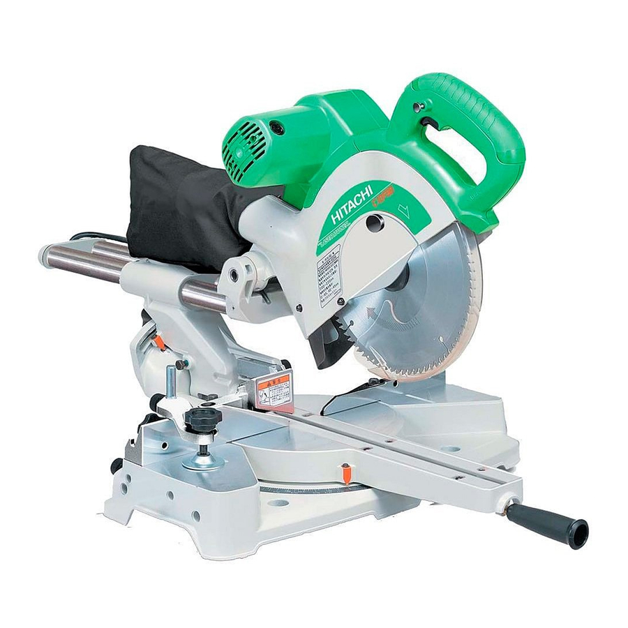
English OPERATION AND MAINTENANCE NOTE: The information contained in this Instruction Manual is designed to assist you in the safe operation and maintenance of the power tool. Some illustrations in this Instruction Manual may show details or attachments that differ from those on your own power tool. NAME OF PARTS MODEL C10FSH/MODEL C10FSB Gear Case... -
Page 9: Specifications
English SPECIFICATIONS Model C 10FSH / C 10FSB Motor Type Series commutator motor Power source Single-phase AC 60Hz Voltage (Volts) Full-load current (Amp) 11.4 Laser Marker Maximum output <1mW CLASS II Laser Product (Only Model Wave length 400~700 nm C10FSH) -
Page 10: Accessories
4 Crown molding Vise Ass’y (Code No. 321434) (Include Crown molding Stopper (L)) 5 Crown molding Stopper (L) (Code No. 321374) 6 Crown molding Stopper (R) (Code No. 321373) NOTE: Accessories are subject to change without any obligation on the part of the HITACHI. APPLICATIONS Wood and aluminum sash. -
Page 11: Preparation Before Operation
English PREPARATION BEFORE OPERATION Make the following preparations before operating the power tool: 1. Installation Base 5/16" (8mm) Bolt 5-29/32"(150mm) 11/32" (9mm) 3 Holes 11-13/16" (300mm) Work Bench 5/16" (8mm) Nut Fig. 4 Attach the power tool to a level, horizontal work bench in accordance with Fig. 4. Select 5/16"... -
Page 12: Before Using
English BEFORE USING 1. Make sure the power source is appropriate for the tool. WARNING: Never connect the power tool unless the available AC power source is of the same voltage as that specified on the nameplate of the tool. Never connect this power tool to a DC power source. -
Page 13: Before Cutting
English BEFORE CUTTING 1. Positioning the table insert Machine Machine Workpiece Workpiece Workpiece Machine Screw Screw Screw Saw Blade Saw Blade Saw Blade Table insert Table insert Table insert [Right angle cutting] [Left bevel angle cutting] [Right bevel angle cutting] Fig. - Page 14 English (4) Turn the 8mm hexagon socket set screw to the right (clockwise) as viewed from behind of the tool, and let it softly contact the tip of the 8mm depth adjustment bolt. 8mm Hexagon Socket 8mm Depth Set Screw Adjustment Bolt Loosen Turn...
- Page 15 English 5. Oblique angle Before the power tool is shipped from the factory, it is adjusted for 0°, right angle, left 45° bevel cutting angle and right 45° bevel cutting angle with the 8mm bolt (A), 8mm bolt (B) and the 8mm bolt (C). When changing the adjustment, change the height of the 8mm bolt (A), 8mm bolt (B) or the 8mm bolt (C) by turning them.
- Page 16 English 9. Confirmation for use of sub fence (A)…(Optional accessory) WARNING: In the case of right bevel cutting, remove the sub fence (A). Supposing it is not able to remove it, Sub Fence It will contact the blade or some part of the tool, causing in serious injury to operator.
- Page 17 English Ink lining can be easily made on this tool to the laser marker. A switch lights up the laser marker. (Fig. 18) Depending upon your cutting choice, the laser line can be aligned Switch with the left side of the cutting width (saw blade) or the ink line on the right side.
-
Page 18: Practical Applications
English PRACTICAL APPLICATIONS WARNING: * To avoid personal injury, never remove or place a workpiece on the table while the tool is being operated. * Never place your limbs inside of the line next to warning sign while the tool is being operated. - Page 19 English In case of compound cutting of left bevel angle and left miter angle, a workpiece of up to 2-3/16" (55mm) can be fixed with a vise assembly mounted on the left side. In case the workpiece height exceeds 2-3/16" (55mm), mount the vise assembly on the opposite side of the inclination of the motor head.
- Page 20 English 5. Cutting large workpieces There may be case when a complete cutting cannot be done Auxiliary depending on the height of workpiece. In this case, mount an 6mm Flad Hd. Board Screw auxiliary board with the 6mm flat head screws and the 6mm nuts using the 7mm holes on the fence surface (two holes on each side).