Hitachi C 10FSB Technical Data And Service Manual
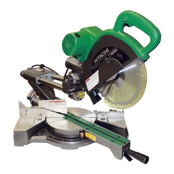
Slide compound saw
Hide thumbs
Also See for C 10FSB:
- Handling instructions manual (45 pages) ,
- Safety & instruction manual (96 pages) ,
- Safety instructions and instruction manual (96 pages)

Related Manuals for Hitachi C 10FSB


Summary of Contents for Hitachi C 10FSB
- Page 1 MODELS C 10FSH C 10FSB Hitachi Power Tools TECHNICAL DATA SLIDE COMPOUND SAW C 10FSH SERVICE MANUAL C 10FSB LIST Nos. C 10FSH: E934 Revised Feb. 2004 C 10FSB: E933 SPECIFICATIONS AND PARTS ARE SUBJECT TO CHANGE FOR IMPROVEMENT...
- Page 2 REMARK: Throughout this TECHNICAL DATA AND SERVICE MANUAL, a symbol(s) is(are) used in the place of company name(s) and model name(s) of our competitor(s). The symbol(s) utilized here is(are) as follows: Competitors Symbols Utilized Company Name Model Name LS1013 MAKITA...
-
Page 3: Table Of Contents
CONTENTS Page 1. PRODUCT NAME ........................... 1 2. MARKETING OBJECTIVE ......................1 3. APPLICATIONS ..........................1 4. SELLING POINTS .......................... 1 4-1. Selling Point Descriptions ....................... 2 5. SPECIFICATIONS .......................... 9 6. COMPARISONS WITH SIMILAR PRODUCTS ................11 7. PRECAUTIONS IN SALES PROMOTION ................... 13 7-1. - Page 4 11-10. Adjustment of Laser Marker Accuracy (Model C 10FSH Only) ............59 11-11. Cutting Accuracy ..........................62 12. REPAIR GUIDE ..........................65 13. STANDARD REPAIR TIME (UNIT) SCHEDULES ................71 Assembly Diagram for C 10FSH Assembly Diagram for C 10FSB...
-
Page 5: Product Name
2. MARKETING OBJECTIVE The new Models C 10FSH and C 10FSB slide compound saws are equipped with not only a fence that is higher than that of the current Model C 10FS but also a sub fence that is higher than the fence to support the workpiece widely for stable cutting. -
Page 6: Selling Point Descriptions
"8-4. Position Adjustment of Laser Line" on page 19. (2) Positive angle stoppers The Models C 10FSH and C 10FSB have positive angle Laser line stoppers in the turn table at the right and the left of the 0˚... - Page 7 (3) High sub fence The Models C 10FSH and C 10FSB have a high sub fence (optional accessory). Use the sub fence for miter cutting, right bevel cutting or crown molding cutting. The sub fence supports the workpiece widely for stable cutting.
- Page 8 Table 3 Unit: mm (inch) Maker HITACHI HITACHI Model Max. C 10FSH C 10FS cutting C 10FSB dimension Width (W) 85 x 312 (3-11/32" x 12-9/32") 85 x 312 Height (H) 90 x 280 (3-11/32" x 12-9/32") 91 x 305 Height x Width (3-9/16"...
- Page 9 HITACHI Model HITACHI C 10FSH Max. C 10FS cutting C 10FSB dimension 85 x 218 (3-11/32" x 8-19/32") Right and left 45˚ 91 x 216 85 x 220 (3-11/32" x 8-15/32") Height x Width 90 x 190 (3-9/16" x 5-25/32") (3-19/32"...
- Page 10 Fig. 11 Saw blade Figures 10 and 11 show the right and left bevel cutting by the Models C 10FSH and C 10FSB. More accurate miter cutting is performed because the same reference plane (surface of the workpiece which contacts the fence) is used in both the left...
- Page 11 By turning the turn table to the left or right and inclining the saw blade section (head) to the left or right, the Models C 10FSH and C 10FSB are capable of compound cutting (bevel and miter, see Figs. 13, 14 and 15) of workpieces with the maximum dimensions shown in Table 7.
- Page 12 *For Europe, the Models C 10FSH and C 10FSB are equipped with a fixed splinter guard to comply with the safety standard.
-
Page 13: Specifications
5. SPECIFICATIONS USA/CAN AUS/NZL 85 mm (3-11/32") x 312 mm (12-9/32"), 88 mm (3-15/32") x 312 mm (12-9/32"), 0˚ (Right angle) 91 mm (3-19/32") x 300 mm (11-13/16") 90 mm (3-9/16") x 280 mm (11") (with aux. board 15 mm (19/32")) 88 mm (3-15/32") x 218 mm (8-19/32"), 85 mm (3-11/32") x 218 mm (8-19/32"), Miter left/right 45˚... - Page 14 USA/CAN EUROPE AUS/NZL Safety (lock-off) switch Provided Not provided Not provided Saw cover lock Not provided Provided Not provided EUROPE USA/CAN/AUS/NZL Laser Maximum output < 1 mW (CLASS ) Po < 3 mW (CLASS ) marker 400 nm to 700 nm (lambda) = 654 nm Wave length (Only Model...
-
Page 15: Comparisons With Similar Products
6. COMPARISONS WITH SIMILAR PRODUCTS Maker/Model HITACHI HITACHI C 10FSH/C 10FSB C 10FS Item 85 x 312 (3-11/32" x 12-9/32") 85 x 312 (3-11/32" x 12-9/32") 91 x 305 (3-19/32" x 12") 0˚ (Right angle) 90 x 280 (3-9/16" x 11") 90 x 295 (3-9/16"... - Page 16 Maker/Model HITACHI HITACHI C 10FSH/C 10FSB C 10FS Item Saw blade drive system Poly V belt + gear Poly V belt + gear Gear On top of workpiece On top of workpiece Under workpiece Slide drive system Slide pipes x 2...
-
Page 17: Precautions In Sales Promotion
7. PRECAUTIONS IN SALES PROMOTION In the interest of promoting the safest and most efficient use of the Models C 10FSH and C 10FSB Slide Compound Saws by all of our customers, it is very important that at the time of sale the salesperson carefully... - Page 18 (2) Warning Label (G) (USA/CAN) Fig. 17 The Warning Label (G) specified by the UL is affixed on the upper right-hand portion of the gear case. Please instruct users to strictly observe the contents 1 to 10 in the Warning Label (G) shown above. (3) Warning Label (H) (at the front of the sub fence) Fig.
- Page 19 (5) Warning Label (M) (at the side of the gear case) Caution label (M) (at the side of the gear case) (USA/CAN) (AUS/NZL) Fig. 20-2 Fig. 20-1 (6) Caution Label (A) (at the top of holder (A)) Fig. 21 --- 15 ---...
- Page 20 (7) Caution Label (J) (at the front of the hinge) and Caution Label (K) (at the side of the turn table) (only Model C 10FSH) Do not stare into laser beam. If your eye is exposed directly to the laser beam, it can be hurt. Caution Labels (J), (P) and Caution Labels (K), (L), (N) are adhered to each machine to comply with the standards for the safe use of laser equipment.
-
Page 21: Relative Standards
7-3. Relative Standards Standards, regulations and guidelines for the safe use of laser equipment [USA] FDA CDRH 21 CFR [AUS/NZL] AS/NZS 2211.1:2001 [EUROPE] EN 60825-1: 2001-11 7-4. Laser Marker (Only Model C 10FSH) The Model C 10FSH is equipped with the laser marker that complies with the Class II requirements of the standard specified in "7-3. -
Page 22: Ambient Illuminance And Visibility Of Laser Line (Only Model C 10Fsh)
7-6. Precautions Concerning Brake (For USA/CAN) The Models C 10FSH and C 10FSB are equipped with a "brake" that stops running when the switch is turned off. Normally the operation is stopped in 5 - 6 seconds when the switch is turned off. If it takes 10 seconds or more to stop, absolutely avoid further use of this machine. -
Page 23: Adjustment And Operational Precautions
8. ADJUSTMENT AND OPERATIONAL PRECAUTIONS 8-1. Confirmation of Saw Blade Lower Limit Position The lower limit of the saw blade cutting depth is factory-adjusted so that when the saw blade is fully lowered, its cutting edge is 9 to 11 mm (13/32" to 7/16") below the upper surface of the turn table in order to cut workpieces completely without cutting the bottom of the turn table groove. -
Page 24: How To Use Guard
* For Europe, the Models C 10FSH and C 10FSB are equipped with a fixed guard. [CAUTION] As the guard may be damaged or broken if the groove is cut too quickly, the customer should be advised to perform this operation slowly and smoothly. - Page 25 (2) Positioning of cutting lines (Adjustment of guard) (For USA/CAN/AUS/NZL) Instruct the customers as follows: Right angle cutting or bevel cutting Saw blade groove Loosen the 6-mm knob bolt, press the guard lightly Guard against the workpiece, and secure it in position. Align the ink line on the workpiece with the groove of 6-mm knob bolt the guard, and cut the workpiece.
-
Page 26: Position Adjustment Of Laser Line (Only Model C 10Fsh)
8-4. Position Adjustment of Laser Line (Only Model C 10FSH) Saw blade The laser line is adjusted to the width of the saw blade at the Workpiece time of factory shipment. Depending upon the cutting choice, align the laser line with the left side of the cutting width (saw Ink line blade) or the right side according to the following procedure. -
Page 27: How To Use The Vise Assembly
CAUTION: Laser radiation - Do not stare into beam. Laser radiation on work table. Do not stare into beam. If your eye is exposed directly to the laser beam, it can be hurt. Do not dismantle it. Do not give strong impact to the laser marker (main body of tool); otherwise, the position of a laser line can go out of order, resulting in the damage of the laser marker as well as a shortened service life. -
Page 28: Adjustment Of Table Insert Position
8-6. Adjustment of Table Insert Position Table inserts are installed on the turn table. When the machine is shipped from the factory, the table inserts are positioned so that there is no chance that the saw blade will come in contact with either side of the saw blade slot even if the machine is used for 45˚... -
Page 29: Cutting Operation
(3) Press cutting ( in Fig. 36) The Models C 10FSH/C 10FSB can be used for press cutting of workpieces up to 85 mm square in a single operation by simply pushing the saw blade section downward in the same manner as the Model C 10FS. - Page 30 Instruct the customer to always slide the saw blade section toward the fence while cutting, as shown by arrow in Fig. 36. On completion of the cutting operation, turn the switch off and wait for the saw blade to come to a complete stop before raising the handle to its original position.
- Page 31 Models C 10FSH/C 10FSB. In the cutting examples illustrated in Fig. 37, the cut surfaces on the sides marked...
- Page 32 For miter cut setting If the turn table has been set to either of the angles described, move the turn table adjusting side handle a little to the right and left to stabilize the position and to properly align the miter scale and the tip of the indicator before the operation starts.
- Page 33 (2) Setting to cut crown moldings at positions in Fig. 39 (See Fig. 42, tilt the head to the left.): Turn the turn table to the left and set the miter angle as follows: For 45˚ type crown moldings: 35.3˚ ( mark) For 38˚...
- Page 34 (3) Setting to cut crown moldings at positions in Fig. 39 (See Fig. 45, tilt the head to the right.): Turn the turn table to the right and set the miter angle as follows: For 45˚ type crown moldings: 35.3˚ ( mark) For 38˚...
- Page 35 Cutting method of crown molding without tilting the saw blade Crown molding vise ass'y Crown molding stopper (R) (1) Crown molding stopper (L) and (R) (optional (optional accessories) (Optional accessories) 6 mm knob accessories) allow easier cuts of crown molding without bolt tilting the saw blade.
-
Page 36: Precautions Concerning Electronic Control
(control element of power supply voltage waveforms). Accordingly, customers should be advised not to operate the Models C 10FSH and C 10FSB in the immediate vicinity of other machines that generate extremely strong magnetic fields or excessive electrical noise. -
Page 37: Adjustment Of Components
9. ADJUSTMENT OF COMPONENTS 9-1. Bevel Angle Adjustment Before shipping from the factory, the height of 8-mm bolts (A), (B) and (C) is adjusted so that the saw blade section (head) will Fixing pin stop at 0˚ (right angle), 45˚ to the left, and 45˚ to the right. To change the head stop positions, instruct the customer to adjust Right bevel the height of 8-mm bolts (A), (B) and (C) by turning them. -
Page 38: Ball Bushing (Linear Bearing)
8-mm hexagon socket set screw (4) Finally, check the perpendicularity of the saw blade with relation to the upper surface 8-mm lock nut of the base [tolerance: 0.15/100 mm]. If it is not within tolerance, adjust 8-mm bolt (A) (stopper for 0˚) as necessary. (Refer to Rear Front the Instruction Manual "Oblique angle".) -
Page 39: Packing
10. PACKING Dust bag (1) Preparation before packing Remove the dust bag from the main body. Turn the turn table 57˚ clockwise and secure the side handle. Push the guard back (Fig. 54). Turn the turn table 57˚ clockwise. Secure Push the guard back. - Page 40 (4) How to install packings (D) and (E) Carton box Packing (D) Put the main body mounted with packings (A), (B) and (C) in the carton box aligning Support with the base packing. Place packing (D) Handle contacting the top and the sides of the support and place packing (E) at the tip of the handle of the head.
-
Page 41: Precautions In Disassembly And Reassembly
[Bold] numbers in the descriptions below correspond to the item numbers in the parts list and exploded assembly diagram of the Model C 10FSH. For the Model C 10FSB, refer to the parts list separately. * Be sure to first disconnect the power plug when performing disassembly or replacement of the saw blade. - Page 42 Item Disassembly Disassembly procedure Necessary tools spots Turn table, base 1. Remove the Knob Bolt M6 x 22 [120] or the Flat Hd. Screw M6 x 25 Phillips screwdriver ass'y [133] and then remove Guard (A) [121]. 2. Hold the Nylon Nut M6 [35] with a 10-mm wrench and remove the 10 mm wrench Flat Hd.
- Page 43 Disassembly Item Disassembly procedure Necessary tools spots Safety cover, link (Lower cover) Fig. 60 10-mm box 1. Remove the Bolt (W/Washers) M6 x 12 (Black) [186] and the wrench Machine Screw (W/Washers) M5 x 12 (Black) [184] with the (standard accessory) 10-mm box wrench (standard accessory) to remove the Spindle Phillips...
- Page 44 Disassembly Item Disassembly procedure Necessary tools spots Spring, support, hinge ass'y, ball bushing, bushing, holder (A) Fig. 61 4-mm hex. bar 1. Remove the Seal Lock Hex. Socket Hd. Bolt M5 x 10 [195]. Note wrench that the Seal Lock Hex. Socket Hd. Bolt M5 x 10 [195] acts as the upper limit stopper of the Gear Case [196] (head) and the Gear Case [196] will move upward when the Seal Lock Hex.
- Page 45 Item Disassembly Disassembly procedure Necessary tools spots Phillips Spring, support, 3. Remove the Machine Screw M4 x 8 [73] to remove the Nylon Clip screwdriver hinge ass'y, ball [104] and Packing Cover [71]. Roll pin puller bushing, 4. Remove the two Roll Pins D6 x 40 [116] by hammering inward. Plastic hammer bushing, holder Then gently hammer the Support [105] outward and remove it from...
- Page 46 Disassembly Item Disassembly procedure Necessary tools spots Belt, pulley (B), spindle ass'y, stopper pin Fig. 62 13-mm wrench 1. Turn the Belt [169] by pulling it outward and remove it. Lock the spindle with the Stopper Pin [213] and pull out Pulley (B) [168] by removing the Nut M8 [164].
- Page 47 Disassembly Item Disassembly procedure Necessary tools spots Armature ass'y, stator ass'y, 142 143 153 154 155 158 159 160 223 224 156 157 144 143 145 146 231 224 housing ass'y, switch, pulley (A) Fig. 63 1. Remove the two Tapping Screws (W/Flange) D3 x 10 (Black) [227] Phillips screwdriver to remove Plate (C) [226].
- Page 48 (1) Loosen the Nut M8 [164] of the Armature Ass'y [177] that is removed in the above step 6 to remove Pulley (A) [161]. [NOTE] Reassemble the Controller [151] according to the wiring diagram in Fig. 70. (For the Model C 10FSB, see the wiring diagram in Fig. 71.) Vise ass'y 1.
- Page 49 Disassembly Item Disassembly procedure Necessary tools spots Laser marker Fig. 65 1. Remove the three Tapping Screws (W/Flange) D4 x 20 (Black) Phillips screwdriver [154] and two Machine Screws (W/Washers) M5 x 25 (Black) [155] to remove Handle (R) [153]. Phillips 2.
- Page 50 [NOTE] Do not lose the Spring [91] and the Clutch Spring [92] as they pop out when the Laser Marker [99] is removed. Reassemble the Switching Power Supply [144] according to the wiring diagram in Fig. 71. (For the Model C 10FSB, see the wiring diagram in Fig. 72.) --- 46 ---...
-
Page 51: Reassembly
5 M Ω. (2) When replacing the Spring [77], apply 3 grams of Hitachi Motor Grease to the inner circumference of the new spring prior to assembly. - Page 52 (5) When replacing the Laser Marker [99], screw the two Seal Lock Hex. Socket Set Screws M5 x 6 [95] into the Laser Marker [99]. To adjust the accuracy of the Laser Marker [99] easily, protrude the tips of the two Seal Lock Hex.
-
Page 53: Wiring Diagram
11-4. Wiring Diagram The Models C 10FSH and C 10FSB are equipped with an overload protection circuit. Carefully ensure that wiring is accomplished as illustrated below. As incorrect wiring will result in lack of rotation, reverse rotation or other malfunctions, close attention is absolutely necessary. - Page 54 C 10FSH EUROPE/AUS/NZL Fig. 69-2 --- 50 ---...
- Page 55 These numbers indicate the terminal numbers of the trigger switch. Black Input Blue AC 120 V White Armature White ass'y Black Brake coil Yellow Stator coil Gray Stator ass'y Controller ass'y Fig. 70-1 C 10FSB EUROPE/AUS/NZL Fig. 70-2 --- 51 ---...
- Page 56 Actual wiring diagram C 10FSH USA/CAN Cord (black) Internal wire (black) Secure the controller pickup portion Cord (A) ass'y (black) near the rib of handle (L) (armature fan side). Stator ass'y (yellow) Cord (A) ass'y (white) Stator ass'y (blue) Cord (A) ass'y (red) Insert each internal wire in the groove of handle (L).
- Page 57 C 10FSH EUROPE/AUS/NZL Cord (blue) Cord (brown) Secure the controller pickup portion near the rib of handle (L) (armature fan side). Internal wire (A) (blue) Connector (B) (white) Internal wire (A) (brown) Internal wire (black) Insert each internal wire in the groove of handle (L).
- Page 58 C 10FSB USA/CAN Cord (black) Secure the controller pickup Cord (A) ass'y (black) portion near the rib of handle (L) (armature fan side). Stator ass'y (yellow) Cord (A) ass'y (white) Stator ass'y (blue) Cord (A) ass'y (red) Insert each internal wire in the groove of handle (L).
- Page 59 C 10FSB EUROPE/AUS/NZL Cord (blue) Secure the controller pickup Cord (brown) portion near the rib of handle (L) (armature fan side). Internal wire (A) (blue) Internal wire (A) (brown) Insert each internal wire in the groove of handle (L). Stator ass'y (black)
-
Page 60: Checking Of Insulation Distance
11-5. Checking of Insulation Distance Do not remove too much of the insulation coating at the internal wire connection. Take care not to let the core of the internal wire stick out the Connector [158] or let the internal wires get caught in a joint between Handle (L) [148] and Handle (R) [153]. -
Page 61: Lubrication
(3) Reassembly of the ball bushing Incorrect The Ball Bushing [106] and Holder (A) [115] are Correct maintained at a smooth fit. When placing the Ball Bushing [106] into Holder (A) [115], gently hammer it with a plastic hammer so that the Ball Bushing [106] Ball bushing is seated into Holder (A) [115] in parallel. -
Page 62: Product Precision
11-9. Product Precision On completion of reassembly, confirm precision tolerances. Item Tolerance 0.2/245 Deflection of dummy disc Squareness between base and fence (A) and fence (B) 0.1/50 (Height of fence) Flatness of fence (A) and (B) Squareness between dummy disc and fence (A) and (B) 0.15/100 Squareness between fences (A) and (B) and slide pipes (Place a square against fences (see Fig. -
Page 63: Adjustment Of Laser Marker Accuracy (Model C 10Fsh Only)
11-10. Adjustment of Laser Marker Accuracy (Model C 10FSH Only) (1) Construction of laser marker and functions of each component The Adjuster [81] located at the side of Hinge (A) Ass'y [75] is a screw used for moving the Laser Marker [99] horizontally. - Page 64 Adjustment of squareness with the fence surface Adjustment of squareness with the base surface Seal Lock Hex. Socket Seal Lock Hex. Socket Set Screw M5 x 6 [95] Set Screw M5 x 6 [95] Holder (B) [98] Holder (B) [98] Laser Marker [99] Laser Marker [99] Laser beam...
- Page 65 Next, insert a 2.5-mm hex. bar wrench into the inlet and adjust the two Seal Lock Hex. Socket Set Screws M5 x 6 [95] so that laser beam is applied to the entire cutting Laser line Rear edge of surface. (Before adjustment of the Laser Marker [99] the cutting surface using a 2.5-mm hex.
-
Page 66: Cutting Accuracy
11-11. Cutting Accuracy Cut appropriate workpieces, measure the squareness with a square or other measuring devices and confirm that accuracy is within the standards listed below. [CAUTION] The test workpieces must be processed with a planer, and their rectangularity and surface flatness must be checked carefully prior to cutting tests. - Page 67 Cutting accuracy: [ A direction ] Square Angle gauge 45˚ δ [ B direction ] Square Fence mounting surface δ Fence mounting surface Square Cutting surface Wood test piece δ Wood test piece Fig. 83 Accuracy δ (mm) Angle 0˚ 0.06 45˚...
- Page 68 (3) Miter cutting Cutting conditions: Test piece: Yellow pine 30 mm (1-3/16") in height, 210 mm (8-1/4") in width All surfaces squarely planed. • • • • • • • • • Saw blade: 255 mm (10") TCT saw blade, number of teeth 40 (Code No. 310878A) Cutting time: 10 sec.
-
Page 69: Repair Guide
12. REPAIR GUIDE Factory Item Phenomenon Cause (s) Inspection, repair or adjustment standard a Inaccurate 0.15/100 • Readjust squareness with the Inaccurate cutting squareness between (Dummy disc) Nylock Bolt M8 x 25 [12]. Inaccurate • • • the turn table and the (Fig. - Page 70 Factory Item Phenomenon Inspection, repair or adjustment Cause (s) standard • Adjust the clearance between the Bushing [108] and slide Hinge (A) ass'y pipe (A) with the Hex. Socket Slide pipe (A) Set Screw M8 x 16 [110]. Ensure that slide pipe (A) slides smoothly with a slide load of 2 to 3 kgf without looseness.
- Page 71 Factory Item Phenomenon Inspection, repair or adjustment Cause (s) standard a Large deflection of • Same as Item 1-(b). Rough cut surface 0.2/245 saw blade. Parallelism = 0.03/44 (Dummy disc) (Causes rough cut surface.) Slide load should b Poor movement of •...
- Page 72 Excessive cutting force • Resharpen saw blade. ------ is applied due to dull saw blade. d Incorrect saw blade is • Use a suitable Hitachi-supplied ------ used. saw blade. • An increased number of teeth on the saw blade increases the cutting resistance.
- Page 73 Factory Item Phenomenon Inspection, repair or adjustment Cause (s) standard a Conroller (pickup) is • Check the position of the Saw blade runs too ------ out of position. Controller [151] referring to fast. Saw blade "11-4. Wiring Diagram". revolution exceeds 4,180 min or it is unstable.
- Page 74 Factory Item Phenomenon Inspection, repair or adjustment Cause (s) standard a Ink line is not right • Make a correct ink line again. Laser line does not ------ angle. match the ink line. (Only Model C 10FSH) Laser emitting aperture b Laser marker accuracy •...
-
Page 75: Standard Repair Time (Unit) Schedules
13. STANDARD REPAIR TIME (UNIT) SCHEDULES Variable MODEL 70 min. Fixed Work Flow C 10FSH Switch Handle (R) Switch Switch Handle (L) Spacer Spindle Ass'y Bearing Holder Link Ball Bearing (6003DD) Ball Bearing (606ZZ) Ball Bearing (608VV) x 2 Lower Guard or Safety Cover Dust Guide Guide Holder... - Page 76 Variable MODEL 70 min. Fixed Work Flow C 10FSB Switch Handle (R) Switch Switch Handle (L) Spacer Spindle Ass'y Bearing Holder Link Ball Bearing (6003DD) Ball Bearing (606ZZ) Ball Bearing (608VV) x 2 Lower Guard or Safety Cover Dust Guide...
- Page 77 Hitachi Power Tools LIST NO. E934 ELECTRIC TOOL PARTS LIST SLIDE COMPOUND SAW 2004 • • Model C 10FSH (E2)
- Page 78 C 10FSH --- 2 --- 2 -- 04...
- Page 79 C 10FSH 142 143 153 154 155 156 157 158 159 160 223 224 144 143 145 146 231 224 2 -- 04 --- 3 -- -...
- Page 80 PARTS C 10FSH ITEM CODE NO. DESCRIPTION REMARKS USED 305-180 CLUTCH SCREW 305-179 CLUTCH SPRING 312-488 CLAMP LEVER 307-725 BOLT (LEFT HAND) M10 315-195 SLEEVE 305-190 METAL SPRING (A) 965-077 SPECIAL WASHER 321-330 SET PIN (A) 949-429 BOLT WASHER M4 (10 PCS.) 949-215 MACHINE SCREW M4X8 (10 PCS.) 320-141...
- Page 81 PARTS C 10FSH ITEM CODE NO. DESCRIPTION REMARKS USED 321-340 SPRING (D) 321-345 FENCE (A) 322-197 BASE ASS’Y 1 INCLUD. 24, 25, 55, 56 321-372 BASE ASS’Y 1 INCLUD. 24, 25, 55, 56 FOR USA, CAN 312-672 BASE RUBBER 315-210 SCALE (A) 949-616 BOLT M6X25 (10 PCS.)
- Page 82 PARTS C 10FSH ITEM CODE NO. DESCRIPTION REMARKS USED 322-619 SUPPORT 321-352 SUPPORT FOR USA, CAN, AUS, NZL 321-347 BALL BUSHING 996-226 FELT 996-223 BUSHING 949-568 LOCK NUT M8 (10 PCS.) 974-500 HEX. SOCKET SET SCREW M8X16 302-459 WING BOLT M6X17 947-859 LOCK SPRING 963-174...
- Page 83 PARTS C 10FSH ITEM CODE NO. DESCRIPTION REMARKS USED 930-804 TERMINAL M4.0 (10 PCS.) 321-380 HANDLE (R) 301-653 TAPPING SCREW (W/FLANGE) D4X20 (BLACK) 880-734 MACHINE SCREW (W/WASHERS) M5X25 (BLACK) 319-503 SWITCH (W/COVER) 321-383 PULLEY COVER 959-141 CONNECTOR 50092 (10 PCS.) FOR USA, CAN, AUS, NZL 980-063 TERMINAL...
- Page 84 PARTS C 10FSH ITEM CODE NO. DESCRIPTION REMARKS USED 949-425 WASHER M6 (10 PCS.) HITACHI LABEL WARNING LABEL (G) 1 FOR USACAN 304-043 MACHINE SCREW (W/WASHERS) M4X10 (BLACK) 877-839 SEAL LOCK HEX. SOCKET HD. BOLT M5X10 321-384 GEAR CASE WARING LABEL (M) FOR USA, CAN...
- Page 85 PARTS C 10FSH ITEM CODE NO. DESCRIPTION REMARKS USED 320-104 CAUTION LABEL (A) EXCEPT FOR USA, CAN, AUS, NZL 2 -- 04 * ALTERNATIVE PARTS --- 9 -- -...
-
Page 86: Standard Accessories
STANDARD ACCESSORIES C 10FSH ITEM CODE NO. DESCRIPTION REMARKS USED 940-543 BOX WRENCH 10MM 998-845 DUST BAG 974-663Z COLLAR (A) FOR D30 HOLE FOR AUS OPTIONAL ACCESSORIES ITEM CODE NO. DESCRIPTION REMARKS USED 321-434 CROWN MOLDING VISE ASS’Y INCLUD. 602, 618 321-388 VISE (B) ASS’Y INCLUD. - Page 87 Hitachi Power Tools LIST NO. E933 ELECTRIC TOOL PARTS LIST SLIDE COMPOUND SAW 2004 • • Model C 10FSB (E2)
- Page 88 C 10FSB --- 2 --- 2 -- 04...
- Page 89 C 10FSB 122 123 129 130 131 132 133 134 135 200 201 208 201 2 -- 04 --- 3 -- -...
- Page 90 PARTS C 10FSB ITEM CODE NO. DESCRIPTION REMARKS USED 305-180 CLUTCH SCREW 305-179 CLUTCH SPRING 312-488 CLAMP LEVER 307-725 BOLT (LEFT HAND) M10 315-195 SLEEVE 305-190 METAL SPRING (A) 965-077 SPECIAL WASHER 321-330 SET PIN (A) 949-429 BOLT WASHER M4 (10 PCS.) 949-215 MACHINE SCREW M4X8 (10 PCS.)
- Page 91 PARTS C 10FSB ITEM CODE NO. DESCRIPTION REMARKS USED 321-345 FENCE (A) 322-197 BASE ASS’Y 1 INCLUD. 24, 25, 54, 55 321-372 BASE ASS’Y 1 INCLUD. 24, 25, 54, 55 FOR USA, CAN 312-672 BASE RUBBER 315-210 SCALE (A) 949-616 BOLT M6X25 (10 PCS.)
- Page 92 PARTS C 10FSB ITEM CODE NO. DESCRIPTION REMARKS USED 321-394 GUARD HOLDER 500-234Z CORD 500-241Z CORD FOR USA, CAN 500-435Z CORD FOR GBR (230V) 500-463Z CORD FOR GBR (110V) 500-447Z CORD FOR SUI 500-439Z CORD FOR AUS, NZL 960-092 WAVE WASHER...
- Page 93 PARTS C 10FSB ITEM CODE NO. DESCRIPTION REMARKS USED 340-555C STATOR ASS’Y 110V INCLUD. 148 340-539D STATOR ASS’Y 120V INCLUD. 148 340-555F STATOR ASS’Y 230V-240V INCLUD. 148 953-174 HEX. HD. TAPPING SCREW D5X55 321-399 BALL BEARING 608VVC2NS7L 360-588U ARMATURE ASS’Y 110V-120V INCLUD.
- Page 94 PARTS C 10FSB ITEM CODE NO. DESCRIPTION REMARKS USED * 188 949-555 NUT M5 (10 PCS.) 1 EXCEPT FOR NZL 988-821 LOCK SPRING 307-732 STOPPER PIN NAME PLATE * 192 322-454 DUST GUIDE * 192 321-364 DUST GUIDE 1 FOR USA, CAN...
- Page 95 STANDARD ACCESSORIES C 10FSB ITEM CODE NO. DESCRIPTION REMARKS USED 940-543 BOX WRENCH 10MM 998-845 DUST BAG * 503 974-663Z COLLAR (A) FOR D30 HOLE 1 FOR AUS OPTIONAL ACCESSORIES ITEM CODE NO. DESCRIPTION REMARKS USED 321-434 CROWN MOLDING VISE ASS’Y INCLUD.
- Page 96 C 10FSB ITEM CODE NO. DESCRIPTION REMARKS USED Printed in Japan --- 10 --- 2 -- 04 (040213N)