Fujitsu AIRSTAGE ARUL7TLAV Installation Manual
Hide thumbs
Also See for AIRSTAGE ARUL7TLAV:
- Service manual (247 pages) ,
- Design & technical manual (978 pages)
Table of Contents
Advertisement
Quick Links
ARUL7TLAV
ARUL9TLAV
ARUL12TLAV
ARUL14TLAV
ARUL18TLAV
TM
INSTALLATION MANUAL
MANUEL D'INSTALLATION
APPAREIL INTÉRIEUR (type conduit)
MANUAL DE INSTALACIÓN
Únicamente para personal de servicio autorizado.
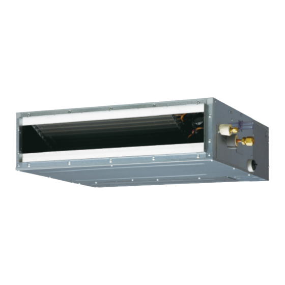
INDOOR UNIT (Duct type)
For authorized service personnel only.
Pour le personnel agréé uniquement.
UNIDAD INTERIOR (Tipo conducto)
PART NO. 9374342358-03
Advertisement
Table of Contents

Related Manuals for Fujitsu AIRSTAGE ARUL7TLAV


Summary of Contents for Fujitsu AIRSTAGE ARUL7TLAV
- Page 1 INSTALLATION MANUAL INDOOR UNIT (Duct type) For authorized service personnel only. MANUEL D’INSTALLATION APPAREIL INTÉRIEUR (type conduit) Pour le personnel agréé uniquement. MANUAL DE INSTALACIÓN UNIDAD INTERIOR (Tipo conducto) Únicamente para personal de servicio autorizado. ARUL7TLAV ARUL9TLAV ARUL12TLAV ARUL14TLAV ARUL18TLAV PART NO.
-
Page 2: Table Of Contents
INSTALLATION MANUAL • Hazard alerting symbols PART NO. 9374342358-03 VRF system indoor unit (Duct type) Electrical Contents SAFETY PRECAUTIONS ..................1 Safety/alert 1.1. IMPORTANT! Please read before starting ............1 1.2. SPECIAL PRECAUTIONS ................. 1 ABOUT THIS PRODUCT..................2 If Necessary, Get Help 2.1. -
Page 3: About This Product
Do not turn ON the power until all work has been completed. Name and Shape Q’ty Application Turning ON the power before the work is completed can cause serious accidents such as electric shock or fi re. Operating Manual If refrigerant leaks while work is being carried out, ventilate the area. If the refrigerant comes in contact with a fl... -
Page 4: Optional Parts
1 (20) or more 2.5. About unit of the length All Fujitsu General products are manufactured to metric units and tolerances. United States customary units are provided for reference only. In cases where exact dimensions and tolerances are required, always refer to metric units. -
Page 5: Installation The Unit (Ceiling Concealed Type)
screw Right side Cover (PIPE side) Duct Grille Left side Inlet air 6 (150) 6 (150) Fan guard or more or more Strong and durable fl oor Strong and 16 (400) 1 (20) 1 (20) 6 (150) durable fl oor or more or more or more... -
Page 6: Installation The Unit (Wall Mounted Type/Floor Standing Concealed Type)
Hanger bolt AR7/9/12/14 AR18 25-9/16 (650) 33-7/16 (850) Hanger Nut A P 7-7/8 (200) × 2 = 15-3/4 (400) P 7-7/8 (200) × 3 = 23-5/8 (600) (Field supply) Washer 3.3A.2. INSTALL THE FILTERS (Accessories) Unit • Install the fi lters to the unit. Nut B (Field supply) 13/16... - Page 7 3.3B.1. UNIT INSTALLATION EXAMPLE (Wall mounted type/Floor standing concealed type) Connect the locally purchased duct. Unit Filter (1) Inlet side • Connect the duct to the locally purchased inlet fl ange. • Connect the fl ange to the body with the locally purchased tapping screws. •...
-
Page 8: Pipe Installation
4.3.1. Flaring 4. PIPE INSTALLATION Use special fl are tool exclusive for R410A. Cut the connection pipe to the necessary length with a pipe cutter. CAUTION Hold the pipe downward so that cuttings will not enter the pipe and remove any burrs. -
Page 9: Installing Heat Insulation
Tighten with 2 wrenches. 5.1A. When drain pump is used Holding wrench • Use general hard polyvinyl chloride pipe ø 3/4 in. (19 mm) [I.D.], ø 1-1/16 in.(27 mm) [O.D.] . • Do not perform a rise, trap and air bleeding. Flare nut Torque wrench •... -
Page 10: Install The Drain Pipe
(1) Ceiling concealed type 5.2. Install the drain pipe Gap of 60 to 78 in. (1.5 to 2 m) (1) Be sure to use supplied Drain hose 1 and Hose band 2 GOOD Downward gradient 2 Hose band (Accessories) 0.10 to 0.19 in. (2.5 to 5.0 mm) 1 Drain hose (Accessories) Supporter... -
Page 11: Electrical Wiring
• STEP1 - STEP3 CAUTION Butt the insulation against the unit. Make sure the drain water is properly drained. Unit 6. ELECTRICAL WIRING Slit WARNING Electrical work must be performed in accordance with this Manual by a person certifi ed under the national or regional regulations. -
Page 12: Electrical Requirement
Breaker shall be located in sight from and readily accessible from all indoor units. 6.1. Electrical requirement *1: When connecting to the Heat Recovery System, refer to the installation manual of the RB unit. Voltage rating 208 / 230 V *2: When connecting the 2-wire type remote controller, Y3 is not used. -
Page 13: Connection Of Wiring
Strip 3/8 in. Ring terminal 6.4. Connection of wiring (10 mm) (1) Remove the cover. (2) Connect the connection cable. Sleeve Cover Screw with spe- Screw with cial washer special washer Cable Ring terminal Screw Ring terminal Terminal block Cable WARNING CAUTION Use ring terminals and tighten the terminal screws to the specifi... -
Page 14: External Input And External Output (Optional Parts)
6.5. External input and external output (Optional DC power supply P.C.B 12 to 24V parts) Load resistance CNA01 CAUTION Do not operate any switches other than prescribed, as it can cause the unit to operate P.C.B improperly or malfunction. Load resistance Use an insulated screwdriver to set the DIP switches. - Page 15 [In the case of “Pulse” input] ● When connecting with unit equipped with a power supply P.C.B Connector Input signal Command Connected OFF → ON Operation device 1 CNA01 or CNA02 OFF → ON Stop Connected device 2 * The last command has priority. Connected device 3 * The indoor units within the same remote controller group operates in the same mode.
-
Page 16: Remote Sensor (Optional Parts)
• Wiring arrangement 6.6. Remote sensor (Optional parts) Core Controller PCB Clamp Connection method • Connection terminals Controller PCB Remote sensor terminal (CN8) • Wiring arrangement Clamp • Use 7 pins for receiver unit cable. Controller PCB • At fi rst, connect the receiver unit cable to the controller PCB. •... -
Page 17: Optional Parts Cable Binding
(1) Indoor unit address 6.9. Optional parts cable binding Rotary switch (IU AD × 1)...Factory setting “0” Rotary switch (IU AD × 10)...Factory setting “0” When connecting multiple indoor units to 1 refrigerant system, set the address at IU AD SW as shown in the Table A. (2) Refrigerant circuit address Rotary switch (REF AD ×... -
Page 18: Custom Code Setting
7.2. Custom code setting 7.4. Switching of drainage function Selecting the custom code prevents the indoor unit mix-up. If contained drain pump is not used, set the drainage function to “Invalid” in the drainage (Up to 4 codes can be set.) function switching. -
Page 19: Function Setting
Function 7.6. Function setting Function Setting number Default Details number Auxiliary • FUNCTION SETTING can be performed with the wired or wireless remote controller. ○ heater (The remote controller is optional equipment) control 1 • Refer to the wired or wireless remote controller manual for detailed setting information. Auxiliary (Set IU AD, REF AD SW to 0) heater... -
Page 20: Check List
10. ERROR CODES 9. CHECK LIST If you use a wired type remote controller, error codes will appear on the remote control- Pay special attention to the check items below when installing the indoor unit(s). After ler display. If you use a wireless remote controller, the lamp on the photodetector unit installation is complete, be sure to check the following check items again.