Table of Contents
Advertisement
Quick Links
Advertisement
Table of Contents

Related Manuals for Toro GrandStand HDX 72514


Summary of Contents for Toro GrandStand HDX 72514
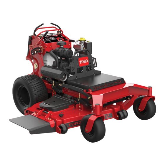
- Page 1 Form No. 3455-289 Rev A GrandStand ® HDX Mower With 60in or 72in TURBO FORCE ® Cutting Unit Model No. 72514—Serial No. 400000000 and Up Model No. 72517—Serial No. 400000000 and Up *3455-289* Register at www.Toro.com. Original Instructions (EN)
- Page 2 Section 4442 or 4443 to use or operate the engine on additional information, contact an Authorized Service any forest-covered, brush-covered, or grass-covered Dealer or Toro Customer Service and have the model land unless the engine is equipped with a spark and serial numbers of your product ready.
-
Page 3: Table Of Contents
Contents Replacing the Fuel Filter ........36 Electrical System Maintenance ......37 Electrical System Safety ........37 Safety ............... 4 Servicing the Battery......... 37 Safety-Alert Symbol..........4 Servicing the Fuses .......... 38 General Safety ........... 4 Drive System Maintenance ........39 Safety and Instructional Decals ...... -
Page 4: Safety
General Safety Safety This product is capable of amputating hands and This machine has been designed in accordance with feet and of throwing objects. Always follow all safety ANSI B71.4-2017. instructions to avoid serious personal injury. • Read and understand the contents of this Safety-Alert Symbol Operator’s Manual before starting the engine. -
Page 5: Safety And Instructional Decals
Safety and Instructional Decals Safety decals and instructions are easily visible to the operator and are located near any area of potential danger. Replace any decal that is damaged or missing. decal112-9028 112-9028 1. Warning—stay away from moving parts; keep all guards and shields in place. - Page 6 decal127-0326 127-0326 3. Remove the key and 1. Read the Operator's Manual. read the Operator's Manual before performing maintenance. 2. Height of cut decal131-3524 131-3524 1. Read the Operator's 3. Cold fluid level Manual. 2. Transmission fluid decal131-3521 131-3521 1. Height of cut decal131-3536 131-3536 1.
- Page 7 decal133-4604 133-4604 1. Thrown object 3. Severing hazard of hand hazard—keep bystanders or foot—keep away from away from the machine. moving parts. 2. Thrown object hazard, 4. Entanglement open deflector—only hazard—keep away operate the machine with from moving parts; keep a deflector or a grass all guards and shields in collector.
- Page 8 decal147-4766 147-4766 1. Read the Operator’s Manual. decal131-3526 131-3526 1. Power takeoff (PTO)—disengaged 5. Reverse 2. Fast 6. Traction drive 7. Engage the handles. 3. Slow 4. Neutral decal139-2878 139-2878 1. Warning—read the Operator’s Manual. 6. Thrown object hazard—keep bystanders away. 2.
- Page 9 decal147-4765 147-4765 1. Parking brake—Disengage 5. Off 2. Parking brake—Engage 6. Fast 3. Engine check 7. Eco mode 4. On 8. Slow...
-
Page 10: Product Overview
Controls Product Overview Become familiar with all the controls before you start the engine and operate the machine. Control Panel g402956 Figure 4 g402968 Figure 5 1. Anti-scalp roller 7. Hydraulic tank 1. Malfunction-indicator light 6. Key switch 2. Front caster wheel 8. -
Page 11: Specifications
The battery light turns on when you turn the key to the To ensure optimum performance and continued safety position and when the charge is below the correct certification of the machine, use only genuine Toro operating level (Figure replacement parts and accessories. Replacement... -
Page 12: Before Operation
Operation – If you spill fuel, do not attempt to start the engine. Avoid creating a source of ignition until the fuel vapors have dissipated. Before Operation – Store fuel in an approved container and keep it out of the reach of children. •... -
Page 13: Adding Fuel
Adding Fuel Recommended Fuel • For best results, use only clean, fresh (less than 30 days old), unleaded gasoline with an octane rating of 87 or higher ((R+M)/2 rating method). • Ethanol: Gasoline with up to 10% ethanol (gasohol) or 15% MTBE (methyl tertiary butyl ether) by volume is acceptable. -
Page 14: Using The Safety-Interlock System
Using the Safety-Interlock Testing the Safety-Interlock System System Service Interval: Before each use or daily DANGER Test the safety-interlock system before you use the machine each time. If safety-interlock switches are disconnected or damaged, the machine could operate Note: If the safety system does not operate as unexpectedly, which will result in serious described below, have an Authorized Service Dealer injury or death. -
Page 15: During Operation
Avoid mowing in • Use only accessories and attachments approved wet conditions. by The Toro® Company. • Before you start the engine, ensure that all drives are in neutral, the parking brake is engaged, and Slope Safety you are in the operating position. -
Page 16: Starting The Engine
Starting the Engine distance (twice the width of the machine) between the machine and any hazard. Use a walk-behind machine or a handheld tool to operate in these Important: Do not engage the starter for more areas. than 5 seconds at a time. If the engine fails to start, wait 15 seconds between attempts. -
Page 17: Shutting Off The Engine
Shutting Off the Engine Operating the Parking Brake CAUTION Always engage the parking brake when you shut off Children or bystanders may be injured if they the machine or leave it unattended. Before each use, move or attempt to operate the machine while check the parking brake for proper operation. -
Page 18: Operating The Mower-Blade-Control Switch (Pto)
Operating the Disengaging the Mower Blades (PTO) Mower-Blade-Control Figure 13 Figure 14 show 2 ways to disengage Switch (PTO) the mower blades. Use the blade-control switch (PTO) in conjunction with the motion-control levers to engage and disengage the mower blades. DANGER The rotating blades under the mower deck are dangerous. -
Page 19: Using The Platform
Using the Platform You can use the machine with the platform in the up or down position. It is your preference on which position to use. WARNING The operator platform is heavy and may cause injury when you raise or lower it. Carefully lower or raise the operator platform, as suddenly dropping it could injure you. -
Page 20: Driving The Machine
Driving the Machine Important: Back the machine over curbs, 1 wheel at a time; driving it forward over curbs could damage the machine. CAUTION Positioning one lever too far in front of the other causes the machine to spin very rapidly. As a result, you may lose control of the machine, causing personal injury to you and damage to the machine. -
Page 21: Side Discharging Or Mulching The Grass
Side Discharging or Adjusting the Height-of-Cut Mulching the Grass The height-of-cut can be adjusted from 38 to 127 mm (1-1/2 to 5 inches) in 6 mm (1/4 inch) increments. This machine has a hinged grass deflector that Note: Using a height-of-cut under 51 mm (2 inches) disperses clippings to the side and down toward the increases the wear on the mower-deck belt. -
Page 22: Adjusting The Anti-Scalp Rollers
Adjusting the Anti-Scalp Rollers Whenever you change the height-of-cut, adjust the height of the anti-scalp rollers. Disengage the blade-control switch (PTO), move the motion-control levers to the N EUTRAL LOCK position, and engage the parking brake. Shut off the engine, remove the key, and wait for all moving parts to stop before leaving the operating position. -
Page 23: Using Weights
Position B Using Weights Use this position when bagging (Figure 23). • Install weights to improve balance. You can add or remove weights to create optimized performance under different operating conditions and for your preference. • Add or remove weights 1 at a time until you achieve the desired handling and balance. -
Page 24: After Operation
Using the Fuel-Shutoff After Operation Valve After Operation Safety Close the fuel-shutoff valve for transport, maintenance, and storage (Figure 25). General Safety Ensure that the fuel-shutoff valve is open when starting the engine. • Always shut off the machine, remove the ignition key, wait for all moving parts to stop, and allow the machine to cool before adjusting, servicing, cleaning, or storing it. -
Page 25: Transporting The Machine
Transporting the Machine Move both bypass levers fully rearward. Use a heavy-duty trailer or truck to transport the machine. Use a full-width ramp. Ensure that the trailer or truck has all the necessary brakes, lighting, and marking as required by law. Please carefully read all the safety instructions. - Page 26 Selecting a Trailer Tie down the machine near the front caster wheels, or front frame holes, and the rear bumper holes with straps, chains, cable, or ropes (Figure 30). Refer to local regulations for tie-down requirements. g403250 g229507 Figure 30 Figure 28 1.
-
Page 27: Maintenance
To ensure optimum performance and continued the engine running. safety certification of the machine, use only • Carefully release pressure from components with genuine Toro replacement parts and accessories. stored energy. Replacement parts and accessories made by • Check the parking brake operation frequently. -
Page 28: Pre-Maintenance Procedures
Maintenance Service Maintenance Procedure Interval • Clean the primary air filter (more often in dirty or dusty conditions). Every 100 hours or yearly, • Replace or clean and gap the spark plug. whichever comes first • Check the valve clearance. Adjust if necessary. Every 250 hours •... -
Page 29: Opening The Engine Guard
Opening the Engine Guard Lubrication Rotate the engine guard forward as shown in Figure Greasing the Machine Grease with No. 2 lithium or molybdenum grease. Disengage the PTO and set the parking brake. Shut off the engine, remove the key, and wait for all moving parts to stop before leaving the operating position. -
Page 30: Lubricating The Motion Controls
Install the seal guards over the wheel hub and insert the wheel into the caster fork. Install the caster bolt and tighten the nut fully. Important: To prevent seal and bearing damage, check the bearing adjustment often by spinning the caster wheel. The wheel should not spin freely (more than 1 or 2 revolutions) or have any side play. -
Page 31: Engine Maintenance
Engine Maintenance Engine Safety • Shut off the engine before checking the oil or adding oil to the crankcase. • Keep your hands, feet, face, clothing, and other body parts away from the muffler and other hot surfaces. Servicing the Air Cleaner Service Interval: Every 100 hours or yearly, whichever comes first—Clean the primary air filter (more often in dirty... -
Page 32: Servicing The Engine Oil
Installing the Filters Checking the Engine-Oil Level Important: Note: To prevent engine damage, always Check the oil when the engine is cold. operate the engine with both air filters and the Important: If you overfill or underfill the cover installed. engine-oil tank with oil and run the engine, you If you are installing new filters, check each filter may damage the engine. - Page 33 Changing the Engine Oil and Filter Note: Dispose of the used oil at a recycling center. Start the engine and let it run for 5 minutes. Note: This warms the oil so that it drains better. Park the machine so that the drain side is slightly lower than the opposite side to ensure that the oil drains completely.
-
Page 34: Servicing The Spark Plug(S)
Removing the Spark Plug(s) Remove the engine-oil filter (Figure 41). Park the machine on a level surface, disengage the blade-control switch (PTO), and engage the parking brake. Shut off the engine, remove the key, and wait for all moving parts to stop before leaving the operating position. -
Page 35: Checking The Spark Arrester
Installing the Spark Plug(s) Fuel System Maintenance DANGER In certain conditions, fuel is extremely flammable and highly explosive. A fire or explosion from fuel can burn you and others and can damage property. Refer to Fuel Safety (page 12) for a complete list of fuel related precautions. -
Page 36: Removing The Fuel Tank
Replacing the Fuel Filter Service Interval: Every 400 hours/Yearly (whichever comes first) Do not install a dirty filter if it is removed from the fuel line. Note: Wipe up any spilled fuel. Park the machine on a level surface, disengage the PTO, and engage the parking brake. -
Page 37: Electrical System Maintenance
Electrical System Maintenance Electrical System Safety • Disconnect the battery or remove the spark-plug wire before making any repairs. Disconnect the negative terminal first and the positive terminal last. Connect the positive terminal first and negative last. • Charge the battery in an open, well-ventilated area, away from sparks and flames. -
Page 38: Servicing The Fuses
Servicing the Fuses The electrical system is protected by fuses. It requires no maintenance. If a fuse blows, check the component or circuit for a malfunction or short. Park the machine on a level surface, disengage the PTO, and engage the parking brake. Shut off the engine, remove the key, and wait for all moving parts to stop before leaving the operating position. -
Page 39: Drive System Maintenance
Drive System Maintenance Adjusting the Tracking If you push both motion-control levers forward the same distance and the machine pulls to 1 side, adjust the tracking as follows. Park the machine on a level surface, disengage the PTO, and engage the parking brake. Shut off the engine, remove the key, and wait for all moving parts to stop before leaving the operating position. -
Page 40: Checking The Tire Pressure
Checking the Tire Pressure Adjusting the Caster-Pivot Bearing Service Interval: Every 50 hours/Monthly (whichever comes first) Service Interval: Every 500 hours/Yearly (whichever Maintain the air pressure in the rear tires at 83 to 97 comes first) kPa (12 to 14 psi). Disengage the blade-control switch (PTO), move Important: the motion control levers to the N... -
Page 41: Removing The Clutch Shim
Removing the Clutch Shim Measure the gap between the rotor and armature. If the gap is greater than 1 mm (0.04 inch), proceed with the following steps: Service Interval: Every 100 hours—Check the clutch. Loosen both brake mounting bolts 1/2 to 1 When the clutch brake has worn to the point where full turn as shown in Figure... -
Page 42: Checking The Wheel-Lug Nuts
is sometimes difficult to measure the true Check and torque the wheel-lug nuts to 115 to 142 gap. N∙m (85 to 105 ft-lb). g302536 Figure 59 1. Feeler gauge g302535 Figure 60 1. Feeler gauge • If the gap is less than 0.010 inch, then install the shim. -
Page 43: Cooling System Maintenance
Brake Maintenance Cooling System Maintenance Testing the Parking Brake Cleaning the Air-Intake Service Interval: Before each use or daily Screen Before each use, test the parking brake on both a level surface and slope. Service Interval: Before each use or daily Always engage the parking brake when you stop the machine or leave it unattended. -
Page 44: Belt Maintenance
Belt Maintenance Route the new belt around the engine pulley and deck pulleys. Checking the Belts Service Interval: Every 100 hours—Check the mower-deck belt(s). Check belts for cracks, frayed edges, burn marks, wear, signs of overheating, or any other damage. The signs of a worn mower belt are squealing while the belt is rotating, blades slipping while you are cutting grass, frayed belt edges, burn marks, and... -
Page 45: Replacing The Transmission Belt
Replacing the Transmission Controls System Belt Maintenance Service Interval: Every 400 hours Adjusting the Every 1,000 hours—Replace the transmission belt. Motion-Control Levers Remove the fuel tank; refer to Removing the Fuel Tank (page 36). If the motion-control levers do not align horizontally, adjust the motion-control levers. -
Page 46: Hydraulic System Maintenance
Hydraulic System Important: Ensure that the flat portion of the cam does not go above a vertical position Specifications (right or left); otherwise you may damage the switch. Hydraulic Fluid Type: Toro ® HYPR-OIL ™ Repeat steps through for the left hydraulic fluid motion-control lever. -
Page 47: Replacing The Hydraulic Fluid And Filters
Remove the hydraulic-reservoir cap. Locate the drain plug in the bottom of each transmission and place a drain pan under the plugs (Figure 70). g301336 Figure 69 1. Hydraulic-tank cap 2. Cold fluid level Remove the cap from the filler neck (Figure 69). -
Page 48: Bleeding The Hydraulic System
Bleeding the Hydraulic System The traction system is self-bleeding, however, it may be necessary to bleed the system if fluid is changed or after work is performed on the system. Park the machine on a level surface, disengage the PTO, and engage the parking brake. Shut off the engine, remove the key, and wait for all moving parts to stop before leaving the g031544... -
Page 49: Mower Deck Maintenance
Mower Deck Maintenance Blade Safety A worn or damaged blade can break, and a piece of the blade could be thrown toward you or bystanders, resulting in serious personal injury or death. g006530 Figure 72 • Inspect the blades periodically for wear or damage. 1. - Page 50 3. Flat of the spindle shaft Operating a machine after incorrectly installing the blade assembly and/or not using genuine Toro blade and blade hardware could allow a blade or blade component to be thrown out from under the deck, resulting in serious injury or death.
-
Page 51: Leveling The Mower Deck
Park the machine on a level surface, disengage the PTO, and engage the parking brake. Shut off the engine, remove the key, and disconnect the spark-plug wires from the spark plugs. Check the tire pressure of both drive tires; refer Checking the Tire Pressure (page 40). - Page 52 Checking the Mower Deck Leveling the Mower Deck Front-to-Rear Pitch Loosen the jam nuts on the linkages you want to adjust. Adjust the tire pressure in the rear tires to the correct specifications. Position 1 blade front-to-rear. Measure at A and B locations from a level surface to the cutting edge of the blade tips (Figure...
-
Page 53: Adjusting The Deck-Lift Spring
Matching the Height-of-Cut Adjusting the Deck-Lift Check the rear tire pressure. Spring Set the height-of-cut to the 76 cm (3 inches) Note: Adjusting the compression spring alters how position; refer to Adjusting the Height-of-Cut much the deck floats and the amount of effort needed (page 21). -
Page 54: Replacing The Grass Deflector
Replacing the Grass Cleaning Deflector Cleaning under the Mower DANGER Deck An uncovered discharge opening allows objects to be thrown toward you or Service Interval: Before each use or daily bystanders. Also, contact with the blade Remove the grass buildup under the mower daily. could occur. -
Page 55: Storage
Storage Shut off the engine, allow it to cool, and drain the fuel tank; refer to Draining the Fuel Tank (page 35), or operate the engine Storage Safety until it shuts off. Start the engine and allow it to run until it •... -
Page 56: Troubleshooting
Troubleshooting Problem Possible Cause Corrective Action The engine does not start, starts hard, or 1. The fuel tank is empty or the shutoff 1. Fill the fuel tank with fuel and open the fails to keep running. valve is closed. valve 2. - Page 57 Problem Possible Cause Corrective Action The cutting height is uneven. 1. Blade(s) are not sharp. 1. Sharpen the blade(s). 2. Cutting blade(s) is/are bent. 2. Install new cutting blade(s). 3. The mower deck is not level. 3. Level the mower deck side-to-side position.
-
Page 58: Schematics
Schematics g425505 145-5225 (Rev. A) - Page 59 While the exposure from Toro products may be negligible or well within the “no significant risk” range, out of an abundance of caution, Toro has elected to provide the Prop 65 warnings. Moreover, if Toro does not provide these warnings, it could be sued by the State of California or by private parties seeking to enforce Prop 65 and subject to substantial penalties.