Table of Contents
Advertisement
Quick Links
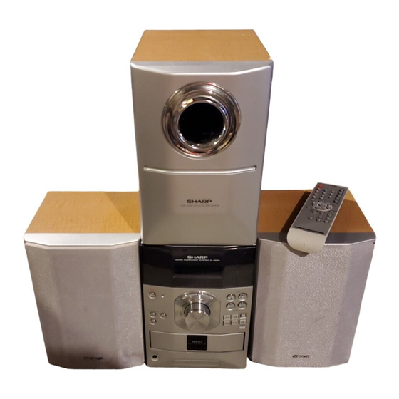
Illustration XL-ES50
[1]
U.S.A. ONLY) ......................................... . ....... 1-1
[2]
SPECIFICATIONS ................................. . ....... 1-1
[3]
NAMES OF PARTS................................ . ....... 1-2
[1]
ADJUSTMENT ....................................... . ....... 2-1
[2]
TEST MODE .......................................... . ....... 2-2
[1]
MAIN PARTS ......................................... . ....... 3-1
[2]
DISASSEMBLY ...................................... . ....... 3-2
[1]
BLOCK DIAGRAM ................................. . ....... 4-1
[1]
WAVEFORMS OF CD CIRCUIT ............ . ....... 5-1
[2]
VOLTAGE............................................... . ....... 5-2
SERVICE MANUAL
CONTENTS
SHARP CORPORATION
No. XXXXXXXXXXXXX
MICRO COMPONENT SYSTEM
MODEL
XL-ES5 Micro Component System consisting of XL-ES5
(main unit), CP-ES5F (front speakers) and CP-ES5SW(sub-
woofer).
MODEL
XL-ES50 Micro Component System consisting of XL-ES50
(main unit), CP-ES50F (front speakers) and CP-ES50SW(sub-
woofer).
• In the interests of user-safety the set should be restored to its origi-
nal condition and only parts identical to those specified be used.
CHAPTER 6. CIRCUIT SCHEMATICS AND PARTS
LAYOUT
[1]
NOTES ON SCHEMATIC DIAGRAM ............6-1
[2]
TYPES OF TRANSISTOR AND LED ............6-1
[3]
GRAM............................................................6-2
CHAPTER 7. FLOWCHART
[1]
TROUBLESHOOTING ..................................7-1
[1]
FUNCTION TABLE OF IC .............................8-1
[2]
FL DISPLAY ..................................................8-6
Parts Guide
This document has been published to be used
for after sales service only.
The contents are subject to change without notice.
XL-ES5/ES50
XL-ES5
XL-ES50
Advertisement
Table of Contents

Related Manuals for Sharp XL-ES5


Summary of Contents for Sharp XL-ES5
-
Page 1: Table Of Contents
XL-ES5/ES50 SERVICE MANUAL No. XXXXXXXXXXXXX MICRO COMPONENT SYSTEM XL-ES5 MODEL XL-ES5 Micro Component System consisting of XL-ES5 (main unit), CP-ES5F (front speakers) and CP-ES5SW(sub- woofer). XL-ES50 MODEL Illustration XL-ES50 XL-ES50 Micro Component System consisting of XL-ES50 (main unit), CP-ES50F (front speakers) and CP-ES50SW(sub- woofer). -
Page 2: Chapter 1. General Description
XL-ES5/ES50 Audio XL-ES5/ES50 Service Manual XLES5 Market CHAPTER 1. GENERAL DESCRIPTION FOR A COMPLETE DESCRIPTION OF THE OPERATION OF THIS UNIT, PLEASE REFER TO THE OPERATION MANUAL. [1] IMPORTANT SERVICE NOTES (FOR U.S.A. ONLY) BEFORE RETURNING THE AUDIO PRODUCT (Fire & Shock Hazard) -
Page 3: Names Of Parts
XL-ES5/ES50 [3] NAMES OF PARTS I Front panel 1. Equalizer Mode Select Button 2. Extra Bass/Demo Mode Button 3. Timer Indicator 4. Power On/Stand-by Button 5. CD Button 6. Tuner (Band) Button 7. Video/Auxiliary Button 8. Disc Compartment 9. Headphone Jack 10. - Page 4 XL-ES5/ES50 I Remote control 1. Remote Control Transmitter 2. Power On/Stand-by Button 3. Direct Track Search Buttons 4. CD Track Down or Fast Reverse, Tuner Preset Down, Time Down Button 5. CD Stop Button 6. Extra Bass Button 7. CD Play or Repeat Button 8.
-
Page 5: Chapter 2. Adjustments
XL-ES5/ES50 Audio XL-ES5/ES50 Service Manual XLES5 Market CHAPTER 2. ADJUSTMENTS TUNER PWB [1] ADJUSTMENT R311 TP-VT FM BAND COVERAGE fL 1. TUNER SECTION L307 fL: Low-range frequency fH: High-range frequency AM BAND COVERAGE fL • AM IF/RF Signal generator: 400 Hz, 30%, AM modulated... -
Page 6: Test Mode
XL-ES5/ES50 [2] TEST MODE "MEMORY/SET"....Shift to step 2 "STOP"......Invalid The test mode applied to this microcomputer has three modes, namely "VIDEO/AUX"....the ordinary test mode for adjustment or measurement, the aging test 2. Step 2 Mode mode, and the self-diagnosis test mode for self-judgment in case of final product inspection. - Page 7 XL-ES5/ES50 5. Step 5 Mode • The TUNER TEST 2 mode is obtained with >> + MEMORY/SET + POWER ON/STAND-BY. ->Turn off AC in the TEST 2 mode to When the CD initialization operation flow is completed, the mute is restore the initial state.
- Page 8 XL-ES5/ES50 5. Timer test Mode (TEST 4) 7. Button input diagnosis Test Mode (TEST 6) When this test mode is obtained, the following display lights for one When the test mode is obtained, the following is displayed. second. (STAND-BY AND DEMO OFF STATUS) Set the current time and timer time according to the following proce- dure to reproduce the timer.
- Page 9 XL-ES5/ES50 8. CD MECHANISM Aging Test Mode (TEST 8) OPEN/CLOSE & 3 DISC CHANGER aging test. DISPLAY: FUNCTION: Enter the TEST MODE 8, MCU control the 3 DISC CHANGER OPEN/ CLOSE. After open finished, tray rotate 1 circle (360 degree). Then close, After close finished, tray rotate 1 circle (360 degree) again.
-
Page 10: Chapter 3. Mechanical Description Removing And Reinstalling The Main Parts
XL-ES5/ES50 Audio XL-ES5/ES50 Service Manual XLES5 Market CHAPTER 3. MECHANICAL DESCRIPTION [1] REMOVING AND REINSTALLING THE MAIN PARTS 1. How to remove CD Disc manually (See Fig. 1,2) CD Changer Perform steps 1 to 7 of the disassembly method to remove the CD... -
Page 11: Disassembly
XL-ES5/ES50 [2] DISASSEMBLY Top Cabinet Caution on Disassembly Follow the below-mentioned notes when disassembling the unit and (A1) x2 reassembling it, to keep it safe and ensure excellent performance: ø3x8mm 1) Be sure to remove the power supply plug from the wall outlet before starting to disassemble the unit. - Page 12 XL-ES5/ES50 Front Panel Chassis (F1) x4 ø4x10mm (H1) x3 ø3x10mm Transformer (H1) x3 ø3x10mm CD Changer Unit Figure 6 (J3) x4 ø3x10mm (G1) x2 CD Servo PWB ø3x10mm (J1) x1 Display PWB (J2) x1 Bracket (G2) x1 (G3) x1 Bracket (J4) x1 ø3x10mm...
- Page 13 XL-ES5/ES50 MEMO — — 3 – 4...
-
Page 14: Chapter 4. Diagrams
XL-ES5/ES50 Audio XL-ES5/ES50 Service Manual XLES5 Market CHAPTER 4. DIAGRAMS [1] BLOCK DIAGRAM L_CH A_GND R_CH S/W_CH –B D_GND TO TUNER PWB CNP602 +12V Q101 Q102 CNS602 CNW602 Q103 M_GND +6.8V A GND Q413 TO CD SERVO PWB D_GND CNS407... - Page 15 XL-ES5/ES50 IC101 LM4733TA POWER AMP. 13 14 L-CH – –B R-CH –B – SUB WOOFER – RLY102 CNP103A/B L IN L OUT A_GND RLY101 R OUT R IN JK101 SUB_RLY IN HEADPHONES SUB_RLY OUT Q112 Q113 Q114 Q110 Q111 –B...
- Page 16 XL-ES5/ES50 AM BAND TO CD COVERAGE fL L306 D305 AM OSC CNP302 TP-VT +12V Q302 AM LOOP ANTENNA L302 Tracking AM ANT. L304 BAND PASS FM ANTENNA FILTER D308 BF301 X301 75KHz 36 35 34 33 32 31 10 11 12 13 14 15...
- Page 17 XL-ES5/ES50 TO CD DISPLAY PWB TO CD SERVO PWB CNS302 CNS406 CNP302 CNP406 TUN R D308 CD R IC602 NJM4558D BUFFER AUX R – – SO601 13 14 15 16 17 18 19 20 21 22 23 VIDEO/AUX AUX_R R-CH...
- Page 18 XL-ES5/ES50 CD CHANGER PWB ASS'Y TO TUNER PWB CNP406 TO MAIN PWB D_GND CNP407 CD_PH2 CNS407 CNS406 CD_PH3 CD_SOL1 MM– CD_SOL2 PHOTO INTERRUPTER MOTOR CONSTANT SOLENOID VOLTAGE Q412 CNP405A CD_CL CD_DI CD_DO CD_WRQ IC401 CD_DRF LC78646E CD_RES SERVO/SIGNAL CONTROL CD_CE...
- Page 19 XL-ES5/ES50 VFD701 FL DISPLAY CNS101 3.8V 3.8V LED701 –30V –B2 Q705 +5.6V TO MAIN PWB D_GND CNP101 +5.6V +5.6V M_GND REMOTE SENSOR RX701 +5.6V D_GND 64 SW1 SW709 71 SW8 POWER_KEY POWER ON/STAND-BY 73 CD_PH KEY2 SW710~SW717 74 MM+ 75 MM-...
-
Page 20: Chapter 5. Circuit Description
XL-ES5/ES50 Audio XL-ES5/ES50 Service Manual XLES5 Market CHAPTER 5. CIRCUIT DESCRIPTION [1] WAVEFORMS OF CD CIRCUIT Stopped 1999/04/07 09:51:15 CH1=200 mV CH2=500 mV 500 ms/div DC 10:1 DC 10:1 (500 ms/div) NORM:20 kS/s Stopped CH1=500 mV CH3=500 mV 500 ms/div... -
Page 21: Voltage
XL-ES5/ES50 [2] VOLTAGE IC101 Q205 IC701 Q506 IC601 IC401 IC301 NO. VOLTAGE NO. VOLTAGE NO. VOLTAGE NO. VOLTAGE NO. VOLTAGE NO. VOLTAGE NO. VOLTAGE NO. VOLTAGE 28 V 1.6 V 2.23 V -28 V -3.9 V 5.6 V 4.7 V 1.0 V... - Page 22 XL-ES5/ES50 MEMO — — 5 – 3...
-
Page 23: Notes On Schematic Diagram
XL-ES5/ES50 Audio XL-ES5/ES50 Service Manual XLES5 Market CHAPTER 6. CIRCUIT SCHEMATICS AND PARTS LAYOUT [1] NOTES ON SCHEMATIC DIAGRAM • Resistor: • The indicated voltage in each section is the one measured by Digi- tal Multimeter between such a section and the chassis with no sig- To differentiate the units of resistors, such symbol as K and M are nal given. -
Page 24: Wiring Side Of Pwb/Schematic Diagram
XL-ES5/ES50 [3] WIRING SIDE OF PWB/SCHEMATIC DIAGRAM MAIN PWB-A1 FM SIGNAL L_CH A_GND R_CH S/W_CH Q101 –B D_GND CNP602 KTC3199 GR R104 6-5 12 - F +12V TO TUNER PWB C134 33/16 Q102 KTC3199 GR R154 6.8K R105 CNS602 CNW602... - Page 25 XL-ES5/ES50 IC101 LM4733TA R143 POWER AMP. SPEAKER BOX ASS'Y L-CH C125 TWEETER C128 13 14 6 ohm WOOFER – C131 – 0.0047 –B – –B 6 ohm – WOOFER R124 C132 C126 R150 0.0047 C137 C138 C135 R110 R111 100/35 –...
- Page 26 XL-ES5/ES50 FROM DISPLA 6-6 2 - D CNS302 CNP302 TUNER PWB-A2 AM BAND D305 COVERAGE fL C311 SVC347S L306 560P AM OSC. TP-VT R304 C310 100K C305 12P(UJ) C308 0.018 JR304 C348 R311 R315 0.022 4.7K +12V C349 R335 R305...
- Page 27 XL-ES5/ES50 FROM DISPLAY PWB FROM CD SERVO PWB 6-6 2 - D 6-9 12 - B CNS302 CNS406 CNP302 CNP406 AM SIGNAL FM SIGNAL CD SIGNAL AUX SIGNAL R603 R602 R601 R622 100K AUX R R621 3.3K C625 10/16 R619 4.7K...
- Page 28 XL-ES5/ES50 DISPLAY PWB-A4 SWITCH PWB ASS'Y(133) CD CHANGER PWB ASS'Y(132) –B CNP501 D_GND D_GND R504A R503A R505A R506A R502A R501A R507A CD_PH2 CD_PH2 R516 CD_PH3 CD_PH3 CD_SOL1 CD_SOL1 MM– MM– CD_SOL2 CD_SOL2 R508A FC501 R787 PHOTO INTERRUPTER CHANGER MOTOR DRIVER...
- Page 29 XL-ES5/ES50 VFD701 FL DISPLAY –B R752A R752B R752C R752D R752E R752F R752G R752H R752I R752J R752K R753A R753B R753C R753D R753E R753F R753G R753H R753I R753J R753K R753L R753M R753N R753O R753P R753Q R753R R753S R753T 74 73 72 71 70 69 68 67 66 65 64 63 62 61 60 59 58 57 56 55 54 53 52 51...
- Page 30 XL-ES5/ES50 CD SERVO PWB-A3 CD SIGNAL CD MECHANISM UNIT (220) C426 C421 C423 100/10 L401 R424 0.82µH R415 1.2K ZD403 FO– DZH05C2+ FO– FO– TR– R428 TR– TR– R417 C406 C414 0.047 47/25 R419 80 79 78 77 76 7...
- Page 31 XL-ES5/ES50 C452 220P CD_CL R440 CD_DI C431 100P R439 CD_DO R438 C430 100P CD_WRQ R437 CNW405 CD_DRF C428 100P R435 6-6 2 - E FROM DISPLAY PWB C429 100P CD_RES C432 100P CD_CE R441 CNP405A C433 0.022 C427 1/50 C426...
- Page 32 XL-ES5/ES50 COLOR TABLE BROWN RD( R) ORANGE M201(218-4) YELLOW FAN MOTOR GREEN CNS602 BLUE VIOLET GRAY TUNER PWB WH( W) WHITE 6-15 11 - B BLACK CNP602 RD-LINE PINK FROM FROM CD SERVO PWB DISPLAY PWB 6-14 2 - C...
- Page 33 XL-ES5/ES50 JACK PWB-A5 M201(218-4) L103 FAN MOTOR R147 FROM CNW203 JK101 DISPLAY PWB HEADPHONES 6-12 2 - A CNS102 CNP203 3 2 1 RD-LINE D219 D217 D218 R433 R220 Q206 C212 7 6 5 4 3 2 1 CNP102 R155...
- Page 34 XL-ES5/ES50 MAIN PWB 6-11 8 - C CNS101 CNP102 RD-LINE MAIN PWB 6-10 12 - E CNS102 CNP101 5 4 3 2 1 DISPLAY PWB-A4 CNW101 R501A R502A R503A R504A VFD701 RX701 R505A R506A FL DISPLAY REMOTE R507A R508A SENSOR...
- Page 35 XL-ES5/ES50 TUNER PWB 6-15 10 - B SWITCH PWB ASS'Y(133) CNP302 CNS302 1 2 3 4 5 6 Q705 R710 R757 C705 TIMER LED701 R773 PHOTO INTERRUPTER SW709 POWER SOLENOID STAND-BY (124) R744 CD SERVO PWB 6-14 2 - G...
- Page 36 XL-ES5/ES50 CD MECHANISM UNIT(220) CD PICKUP UNIT SPINDLE MOTOR CD MOTOR PWB PICKUP IN SLED MOTOR CNW402 4 3 2 1 RD-LINE CNP407 RD-LINE MAIN PWB CNS407 CNS406 6-10 5 - C CNW407 CNW406 C448 FROM Q411 FM/AM LO C449...
- Page 37 XL-ES5/ES50 FROM FROM DISPLAY PWB MAIN PWB 6-13 9 - A 6-10 6 - B TUNER PWB-A2 CNS602 CNS302 CNP302 CNP602 R338 TP-VT R311 1 2 3 4 5 6 R337 R101 C318 L307 FM BAND COVERAGE fL R630 R335...
-
Page 38: Troubleshooting
XL-ES5/ES50 Audio XL-ES5/ES50 Service Manual XLES5 Market CHAPTER 7. FLOWCHART [1] TROUBLESHOOTING 1. When the CD does not function The CD section may not operate when the objective lens of the optical pickup is dirty. Clean the objective lens, and check the playback operation. - Page 39 XL-ES5/ES50 Stopped (1) Focus-HF system check. CH1=500 mV CH3=500 mV 500 ms/div DC 10:1 DC 10:1 (500 ms/div) NORM:20 kS/s Although a CD is inserted and the cover is closed, "NO DISC" is displayed. Press the OPEN/CLOSE switch (SW717) without inserting a disc, and try starting the playback operation.
- Page 40 XL-ES5/ES50 (2) Focus-HF system check. Check the TE waveform at pin 15 on IC 401. If the waveform shown in Figure 4 appears and soon after NO The tracking servo is not activated. DISC appears? Check the peripheral circuits at pins 14, 15 and 20 on IC401, and FC401.
- Page 41 XL-ES5/ES50 (4) PLL system check. Stopped 1999/04/05 17:33:17 CH1=500 mV CH3=1 V CH4=1 V 500 ms/div DC 10:1 DC 10:1 DC 10:1 (500 ms/div) NORM:20 kS/s When a disc is loaded, start play operation. PDO1 The HF waveform is normal, but the TOC data cannot be read.
-
Page 42: Function Table Of Ic
XL-ES5/ES50 Audio XL-ES5/ES50 Service Manual XLES5 Market CHAPTER 8. OTHERS [1] FUNCTION TABLE OF IC IC401 VHiLC78646E-1: Servo/Signal Control (LC78646E) (1/2) Pin No. Terminal Name Input/Output Setting in Reset Function SLCO Output — Control output. For slice level SLCIST Input —... - Page 43 XL-ES5/ES50 IC401 VHiLC78646E-1: Servo/Signal Control (LC78646E) (2/2) Pin No. Terminal Name Input/Output Setting in Reset Function RVSS — — GND for Right channel. Must be connected to 0 V. Right channel RCHO Output LVDD/2 Right channel output. D/A converter RVDD Input —...
- Page 44 XL-ES5/ES50 IC401 VHiLC78646E-1: Servo/Signal Control (LC78646E) 75 74 72 71 69 68 66 65 63 62 SLCO DATA SLCIST DATACK EFMIN LRSY ASDFIN RFVDD ASDACK RFVSS ASLRCK FIN1 16MOUT FIN2 EFLG TIN1 TIN2 XVSS LC78646E VREF FSX/16MIN REF1 XOUT XVDD...
- Page 45 XL-ES5/ES50 IC701 RH-iXA008SJZZ: System Microcomputer (IXA008SJ) (1/2) IC701 RH-iX0058SJZZ: System Microcomputer (IX0058SJ) (1/2) Pin No. Port Name Terminal Name Input/Output Function P16/T1PWML TIMER LED Output LED DRIVER (H LED ON). P17/T1PWMH/BUZ P MUTE Output MUTE (03.11.4). PWM2/IN4/T1IN PROG1 — PROGRAM USE.
- Page 46 XL-ES5/ES50 IC701 RH-iXA008SJZZ: System Microcomputer (IXA008SJ) (2/2) IC701 RH-iX0058SJZZ: System Microcomputer (IX0058SJ) (2/2) Pin No. Port Name Terminal Name Input/Output Function S22/PC6 — VFD SEGMENT. S23/PC7 — VFD SEGMENT. S24/PD0 — VFD SEGMENT. S25/PD1 — VFD SEGMENT. S26/PD2 — VFD SEGMENT.
-
Page 47: Fl Display
XL-ES5/ES50 [2] FL DISPLAY VFD701 VVK251116//-1 GRID ASSIGNMENT ANODE CONNECTION OUTER DRAWING PIN CONNECTION 8 – 6... - Page 48 XL-ES5/ES50 MEMO — — 8 – 7...
- Page 49 XL-ES5/ES50 PARTS GUIDE MICRO COMPONENT SYSTEM XL-ES5 MODEL XL-ES5 Micro Component System consisting of XL-ES5 (main unit), CP-ES5F (front speakers) and CP-ES5SW (subwoofer). XL-ES50 MODEL XL-ES50 Micro Component System consisting of XL-ES50 (main unit), CP-ES50F (front speakers) and CP-ES50SW (subwoofer).
- Page 50 XL-ES5/ES50 PRICE PRICE DESCRIPTION PARTS CODE DESCRIPTION PARTS CODE RANK RANK INTEGRATED CIRCUITS FILTERS IC101 VHILM4733TA-1 AY Power Amp.,LM4733TA BF301 RFILR0008AWZZ AE Band Pass Filter IC201 VHIKIA7805API AF Voltage Regulator,KIA7805API CF301 RFILFA001SJZZ AE FM IF IC202 VHIKIA7812API AE Voltage Regulator,KIA7812API...
- Page 51 XL-ES5/ES50 PRICE PRICE DESCRIPTION PARTS CODE PARTS CODE DESCRIPTION RANK RANK AB 10 µF,16V,Electrolytic C307 VCCUPA1HJ100D AA 10 pF (UJ),50V C601~603 RC-GZA106AF1C AB 0.018 µF,25V AB 47 µF,16V,Electrolytic C308 VCKYCY1EB183K C604 RC-GZA476AF1C AA 0.001 µF,50V AB 10 µF,16V,Electrolytic C309 VCKYPA1HB102J...
- Page 52 XL-ES5/ES50 PRICE PRICE DESCRIPTION PARTS CODE PARTS CODE DESCRIPTION RANK RANK R214 VRD-RT2HD470J AA 47 ohms,1/2W R509 VRS-CY1JB391J AA 390 ohms,1/16W R215 VRS-CY1JB332J AA 3.3 kohms,1/16W R510 VRD-ST2CD471J AA 470 ohms,1/6W R216 VRS-CY1JB273J AA 27 kohms,1/16W R511 VRD-ST2CD223J AA 22 kohms,1/6W...
- Page 53 XL-ES5/ES50 PRICE PRICE DESCRIPTION PARTS CODE PARTS CODE DESCRIPTION RANK RANK R753H VRS-CY1JB823J AA 82 kohms,1/16W RLY102 RRLYDA001SJZZ AH Relay R753I VRS-CY1JB823J AA 82 kohms,1/16W RX701 VHLGP1UD261-1 AK Remote Sensor,GP1UD261 R753J VRS-CY1JB823J AA 82 kohms,1/16W SO101 QTANAA001SJZZ AF Terminal,Speaker 1 SO202...
- Page 54 PCUSG0017SJSA AB Cushion,Leg B3CPES5F Speaker Box Ass’y,L-CH/R-CH GCABCA004SJSA Top Cabinet [XL-ES5] [XL-ES5] GCABCA004SJSB AK Top Cabinet [XL-ES50] B3CPES5SW Sub Woofer Box Ass’y [XL-ES5] GCABDA005SJSA Chassis,Main [XL-ES5] B3CPES50F Speaker Box Ass’y,L-CH/R-CH GCABDA005SJSB AK Chassis,Main [XL-ES50] [XL-ES50] GCOVAA005SJ01 Changer Cover Ass’y [XL-ES5] B3CPES50SW Sub Woofer Box Ass’y...
- Page 55 XL-ES5/ES50 161x2 164x2 164x2 161x2 164x2 162x2 164x2 166x3 163x2 Figure 6 CD CHANGER MECHANISM EXPLODED VIEW – 6 –...
- Page 56 XL-ES5/ES50 614x2 PWB-A2 607x4 617x4 614x2 608x2 Silicon 606x2 613x2 614x2 Grease IC101 218-4 602x4 (M201) 605x2 218-3 612x3 616x2 218-1 IC201 218-2 T201 IC203 Silicon IC202 Grease PWB-A1 606x2 606x2 612x3 Silicon Grease D201 PWB-A3 236x2 614x2 236x2 237x6...
- Page 57 XL-ES5/ES50 PACKING METHOD (FOR U.S.A. ONLY) Setting position of switches and knobs CD Lid CLOSE Polyethylene Bag,Unit SSAKHA006SJZZ Packing Add.,Unit,Left SPAKAA012SJZZ Cushion Bag SSAKHA014SJZZ Label,Pop Label,UL TLABZA024SJZZ TLABSA003SJZZ Packing Add.,Unit,Right SPAKAA013SJZZ Remote Control SUB WOOFER ASS'Y Polyethylene Bag,Accessories B3CPES5SW(ES5) SSAKA0014SJZZ...
- Page 58 XL-ES5/ES50 — M E M O — – 9 –...
- Page 59 XL-ES5/ES50 — M E M O — – 10 –...
- Page 60 XL-ES5/ES50 © COPYRIGHT 2004 BY SHARP CORPORATION ALL RIGHTS RESERVED. No part of this publication may be reproduced, stored in a retrieval system, or transmitted in any form or by any means, electronic, mechanical, photocopying, recording, or otherwise, without prior written permission of the publisher.