Table of Contents
Advertisement
Quick Links
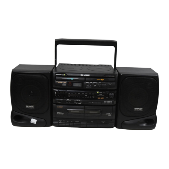
Illustration: GX-CH170Z
SPECIFICATIONS ............................................................................................................................................................. 2
VOLTAGE SELECTION (GX-CH170Z ONLY) ................................................................................................................... 2
NAMES OF PARTS ........................................................................................................................................................... 3
REMOTE CONTROL ......................................................................................................................................................... 4
DISASSEMBLY .................................................................................................................................................................. 5
REMOVING AND REINSTALLING THE MAIN PARTS ..................................................................................................... 7
FITTING OF DIAL POINTER ............................................................................................................................................. 8
ADJUSTMENT ................................................................................................................................................................... 9
TROUBLESHOOTING (CHANGER/CD SECTION) ........................................................................................................ 11
NOTES ON SCHEMATIC DIAGRAM .............................................................................................................................. 16
TYPES OF TRANSISTOR AND LED ............................................................................................................................... 16
BLOCK DIAGRAM ........................................................................................................................................................... 17
SCHEMATIC DIAGRAM / WIRING SIDE OF P.W.BOARD ............................................................................................. 20
WAVEFORMS OF CD CIRCUIT ...................................................................................................................................... 35
FUNCTION TABLE OF IC ................................................................................................................................................ 36
LCD SEGMENT ............................................................................................................................................................... 37
PARTS GUIDE/EXPLODED VIEW
DIFFERENCE BETWEEN GX-CH170X AND GX-CH170Z
TUNER
FINE TUNING
FM STEREO INDICATOR
POWER SOURCE
SERVICE MANUAL
• In the interests of user-safety the set should be restored to its
CONTENTS
GX-CH170X
2 BAND
AC 220-240 V,50 Hz
SHARP CORPORATION
GX-CH170X
GX-CH170Z
original condition and only parts identical to those specified
should be used.
GX-CH170Z
4 BAND
AC 110-127/220-240 V,
50/60 Hz
GX-CH170X/CH170Z
No. S6631GXCH170Z
Page
Advertisement
Table of Contents

Related Manuals for Sharp GX-CH170X


Summary of Contents for Sharp GX-CH170X
-
Page 1: Table Of Contents
SCHEMATIC DIAGRAM / WIRING SIDE OF P.W.BOARD ..................... 20 WAVEFORMS OF CD CIRCUIT ............................35 FUNCTION TABLE OF IC ..............................36 LCD SEGMENT ................................37 PARTS GUIDE/EXPLODED VIEW DIFFERENCE BETWEEN GX-CH170X AND GX-CH170Z GX-CH170X GX-CH170Z TUNER 2 BAND 4 BAND... -
Page 2: Specifications
GX-CH170X/CH170Z FOR A COMPLETE DESCRIPTION OF THE OPERATION OF THIS UNIT, PLEASE REFER TO THE OPERATION MANUAL. SPECIFICATIONS General Radio Power source: AC 220-240 V, 50 Hz (GX-CH170X) DC 12 V [ "D" size (UM/SUM-1, Frequency range: FM; 87.6 - 108 MHz... -
Page 3: Names Of Parts
40. (TAPE 1) Stop/Eject Button: 41. (TAPE 2) Play Button: 42. (TAPE 2) Stop/Eject Button: 43. (TAPE2) Cassette Compartment Rear panel 44. FM Telescopic Rod Aerial (GX-CH170X) 44. FM/SW Telescopic Rod Aerial (GX-CH170Z) 45. Headphone Socket 46. Speaker Terminals 47. Battery Compartment 48. -
Page 4: Remote Control
12. Track Up/Cue Button: 13. Stop Button: 14. Programme Button 15. Volume Up/Down Buttons: REMOTE CONTROL (Illustration: GX-CH170X) Notes concerning use: Replace the batteries if control distance decreases or oper- ation becomes erratic. Periodically clean the transmitter LED on the remote control and the sensor on the main unit with a soft cloth. -
Page 5: Disassembly
GX-CH170X/CH170Z DISASSEMBLY Caution on Disassembly Follow the below-mentioned notes when disassembling the unit and reassembling it, to keep it safe and ensure excellent ( A1 ) x2 Front performance: ø3 x6mm Cabinet 1. Take cassette tape and compact disc out of the unit. - Page 6 GX-CH170X/CH170Z ( K1 ) x2 ø2.6 x8mm ( K1 ) x3 ( F2 ) x1 Front ø2.6 x10mm ( F1 ) x5 Cabinet ø3 x10mm ( K1 ) x1 ø2.6 x8mm ( G1 ) x3 Display ø3 x10mm ( G2 ) x2...
-
Page 7: Removing And Reinstalling The Main Parts
GX-CH170X/CH170Z REMOVING AND REINSTALLING THE MAIN PARTS TAPE MECHANISM SECTION TAPE 1 Record/Playback Perform steps 1, 2, 3, 4, 5, 7 and 8 of the disassembly method Erase Head Head to remove the tape mechanism. How to remove the record/playback and erase heads (TAPE 1) (See Fig. -
Page 8: Fitting Of Dial Pointer
FITTING OF DIAL POINTER 1. Remove the three screws, and remove the tuner PWB from the tuner frame. (See Fig. 8-2) [GX-CH170X] 1. Remove the four screws, and remove the tuner PWB from the tuner frame. (See Fig. 8-2) [GX-CH170Z] 2. -
Page 9: Adjustment
GX-CH170X/CH170Z ADJUSTMENT MECHANISM SECTION TUNER SECTION • Driving Force Check fL: Low-range frequency fH: High-range frequency Torque Meter Specified Value • FM IF/RF PLAY: TW-2412 Tape 1: Over 50 g Tape 2: Over 100 g Specified Instrument Test Stage Value/Adjusting Point Connection •... - Page 10 GX-CH170X/CH170Z CD SECTION Since this CD system incorporates the following automatic adjustment function, when the pickup is replaced, it is necessary to reajust it. Since this CD unit does not need adjustment, the combination of PWB and laser pickup unit is not restricted.
-
Page 11: Troubleshooting (Changer/Cd Section)
GX-CH170X/CH170Z TROUBLESHOOTING (CHANGER CONTROL SECTION) When the changer mechanism fails to operate normally. Operation failure may be caused by blocking of disc at the changer mechanism tray. Therefore, it is necessary to check at first to see whether there is any disc blocking. - Page 12 GX-CH170X/CH170Z • The disc tray cannot be opened and closed. Check the +7.5V power line. Is +7.4V applied to the pin 6 of IC761? Does the LCD "?" indication rotate when the main unit Check the main unit button or remote control.
- Page 13 GX-CH170X/CH170Z TROUBLESHOOTING (CD SECTION) When the CD does not function When the CD section does not operate When the objective lens of the optical pickup is dirty,this section may not operate.Clean the objective lens,and check the playback operation.When this section does not operate even after the above step is taken,check the following items.
- Page 14 GX-CH170X/CH170Z • Playback can only be performed when a disc is loaded. Check the laser diode driver. Is the Focus servo active? (Can you hear it working?) Check the area around IC801(16) - (21) (focus servo circuit). Does the DRF signal change from "L" to "H"?
- Page 15 GX-CH170X/CH170Z • Checking the spin system. Play operation is performed without disc. The spin driver circuit is normal. The turntable rotates a little. Check the periphery of IC801 pins 23 to 27, pin 39 and pin 40, The turntable fails to rotate or rotates at high speed.
-
Page 16: Notes On Schematic Diagram
DUBBING SPEED/BEAT CANCEL NORMAL A— SW706 CD-REVIEW ON—OFF NORMAL B— SW707 CD-DISC 1-2 ON—OFF HIGH C/A—B—C SW708 CD-RANDOM ON—OFF SW253 BAND [GX-CH170X] FM—AM SW709 VOLUME UP ON—OFF SW253 TAPE SELECTOR/FM MODE NORMAL—CrO2/ SW710 VOLUME DOWN ON—OFF [GX-CH170Z] FM STEREO— FM MONO... -
Page 17: Block Diagram
GX-CH170X/CH170Z Figure 17 BLOCK DIAGRAM (1/3) – 17 –... - Page 18 GX-CH170X/CH170Z Figure 18 BLOCK DIAGRAM (2/3) – 18 –...
- Page 19 GX-CH170X/CH170Z Figure 19 BLOCK DIAGRAM (3/3) – 19 –...
-
Page 20: Schematic Diagram / Wiring Side Of P.w.board
GX-CH170X/CH170Z M701 SPIN MOTOR CD MOTOR PWB-E PICKUP UNIT SW702 PICKUP IN M702 SLIDE MOTOR CNP803 CNS801 2 3 4 5 6 7 8 12 10 CD SERVO PWB-D CNS802 Q805 C807 C848 CNS803 R812 R805 R806 R810 C813 R842... - Page 21 GX-CH170X/CH170Z GX-CH170X (211) TUNER PWB-B CNW2 P24 5 - C TO MAIN PWB ROD ANNTENA (210) GX-CH170Z CNS2 AM BAR ANTENNA CNS3 VR500 FINE BI500 TUNING LED500 FINE TUNING PWB-A9 TUNER PWB-B (211) CNP3 CNW2 P26 5 - C 1 2 3...
- Page 22 GX-CH170X/CH170Z CD SERVO PWB-D LASER DRIVER Q805 KTA1266 GR R842 C849 0.022 C848 1/50 C838 0.01 R871 C850 4.7K C845 4.7/50 – FIN2 – – FIN1 FEBAL – – – FOSTA C803 – 0.1/50 TOSTA R803 DGND – 2FREQ R802 TE–...
- Page 23 GX-CH170X/CH170Z PICKUP UNIT 1/16 R801 C802 C801 47/10 0.01 LT0H30M1 2200P 2200P TR– TR– C847 R860 FO– FO– FO– 0.01 TR– ACTUATOR CNS801 SERVO/SIGNAL 64 63 62 57 56 55 35 52 51 50 49 IC802 61 60 59 58...
- Page 24 GX-CH170X/CH170Z GX-CH170X COLOR R D ( R ) W H ( W ) TABLE BROWN ORANGE YELLOW GREEN BLUE VIOLET GRAY WHITE BLACK PINK CNP1 P21 9 - B TO TUNER PWB FW652 CNS651 F651 T2.5A SO651 L 250V D652...
- Page 25 GX-CH170X/CH170Z DUBBING SPEED HIGH NORMAL BAND FM AUTO BEAT CANCEL SW651 FUNCTION SW253 SW251 TUNER TAPE P31 11 - H CNP602 TO DECK PWB R672 Q660 R500 P31 11 - H FW602 FW603 CNP603 TO DECK PWB Q651 R651 C657...
- Page 26 GX-CH170X/CH170Z GX-CH170Z COLOR RD(R) WH(W) TABLE BROWN ORANGE YELLOW GREEN BLUE VIOLET GRAY WHITE BLACK PINK CNP1 P21 8 - F TO TUNER PWB FW652 CNS651 SO651 D652 AC INPUT AC110-127/220-240V SO651 C652 50/60Hz C651 FW652 D654 T651 F651 POWER TRANSFOMER T2.5A...
- Page 27 GX-CH170X/CH170Z TAPE SELECTOR DUBBING SPEED CrO2 NORMAL HIGH NORMAL STEREO MONO BEAT CANCEL FM MODE SW651 FUNCTION SW253 SW251 TUNER TAPE Q661 P31 11 - H CNP602 TO DECK PWB R672 Q660 R670 R500 L500 P31 11 - H FW602...
- Page 28 GX-CH170X/CH170Z TO MIC P33 8-E TO GRAPHIC EQALIZER CNS501 CNP501 TO TUNER PWB P34 5-H CNP1 R937 FOR Z 1 2 3 4 5 TO TUNER PWB P34 5-C CNP1 FM MODE SW253-A FM STEREO FM MONO L501 L500 R500 10µH...
- Page 29 Z ONLY RECORD SIGNAL +12V Q661 Q660 KRC102 M R671 2SB561 C R670 DUBBING NOR A X : GX-CH170X SWITCHING NOR B Z : GX-CH170Z HIGH C SW251-A BEAT CANCEL R672 (DUBBING) X ONLY Figure 29 SCHEMATIC DIAGRAM (4/7) – 29 –...
- Page 30 GX-CH170X/CH170Z Q701 Q702 Q703 D701 R746 C704 R745 D703 RX701 R753 R748 R752 Q704 R768 C707 P20 4 - H X701 R707 CNS852 R719 R718 TO CD SERVO PWB R743 R717 IC901 R742 R716 R741 R740 R714 SWITCH PWB-A7 R739...
- Page 31 GX-CH170X/CH170Z R907 Q901 R923 R935 R924 R908 R905 R915 R906 C901 C910 C902 R914 R903 R916 C906 R913 B C E R909 Q902 C903 R911 VR901 ~ VR904 R912 R921 C904 C920 R910 C907 R922 R917 C911 R919 R920 C921...
- Page 32 GX-CH170X/CH170Z DECK PWB-C R220 R219 SWITCH PWB-7 SWITCH PWB-8 R201 R222 6.8K R786 TAPE2 LED703 PLAYBACK HEAD 3N4GDN32 R202 R231 L-CH R787 TRAY2 OPEN/ CLOSE R211 SW713 FW505 SW714 TRAY1 6.8K OPEN/CLOSE R209 R207 R-CH 150K 6.8K SW201-D SW201-C R215 C217 6.8K...
- Page 33 FM SIGNAL D701 100K 1SS133 PLAYBACK SIGNAL C712 RECORD SIGNAL R768 Q704 KRC102 M BEAT CANCEL X : GX-CH170X Z : GX-CH170Z R738 ~ R743, R767 : 15K CD5V CD-GND PUIN SQOUT P22 1-G CNS852 SL– TO CD SERVO PWB...
- Page 34 GX-CH170X/CH170Z GX-CH170X B. P. F. ANTENNA FM FRONT END 330K 820K 0.022 LA1186N 1 2 3 RF AMP 1.2K 0.022 220/10 470P 6.8K 5 9 6 3.3/50 3.9K (CH) FM DET 3.3/50 0.001 10/16 STB AM RF +B FM DET...
-
Page 35: Waveforms Of Cd Circuit
GX-CH170X/CH170Z WAVEFORMS OF CD CIRCUIT STOP PLAY 50ms REVIEW 0.50 V 10.0 V IC801 20 F.E FOCUS SERCH 50ms 10.0 V 50ms 5.0 V 0.50 V IC801 54 DRF 50ms 1.00 V 0.5ms 10.0 V 0.5ms 0.5ms 1.00 V 10.0 V 0.5ms... -
Page 36: Function Table Of Ic
GX-CH170X/CH170Z FUNCTION TABLE OF IC IC901 RH-iX0146AWZZ (IX0146AW): System Control Microcomputer Terminal Pin No. Port Name Input/ Function Name Output MTCONT2 Output Changer mechanism motor control output No.2. POWER IN Input Power key input. POWER ON Output "L" when power is turned on. -
Page 37: Lcd Segment
GX-CH170X/CH170Z LCD801 RV-LX0020AWZZ SEGMENT VOLUME RANDOM PROGRAM COMMON VOLUME RANDOM PROGRAM Figure 37 LCD SEGMENT – 37 –... - Page 38 GX-CH170X/CH170Z — M E M O — – 38 –...
- Page 39 “HOW TO ORDER REPLACEMENT PARTS” To have your order filled promptly and correctly, please furnish the For U.S.A. only following information. Contact your nearest SHARP Parts Distributor to order. 1. MODEL NUMBER 2. REF. No. 3. PART NO. 4. DESCRIPTION For location of SHARP Parts Distributor, Please call Toll-Free;...
- Page 40 GX-CH170X/CH170Z PRICE PRICE PART CODE DESCRIPTION PARTS CODE DESCRIPTION RANK RANK INTEGRATED CIRCUITS FILTERS VHILA1186N/-1 AE FM Front End,LA1186N 92LFILT-F1342A AD FM IF VHILA1805//-1 AM FM/AM IF MPX.,LA1805 RFILA0006AWZZ AG AM IF [X] IC201 VHIAN7345K/-1 AM Playback and Record/ Playback...
- Page 41 GX-CH170X/CH170Z PRICE PRICE DESCRIPTION DESCRIPTION PART CODE PARTS CODE RANK RANK AA 0.022 µF,25V AB 100 µF,10V,Electrolytic C20,21 VCTYMN1EF223Z C609,610 RC-GZA107AF1A AA 0.0022 µF,16V [X] AC 0.1 µF,50V,Mylar VCTYMN1CX222K J C611,612 RC-QZA104AFYJ AA 0.0047 µF,16V [Z] AD 1000 µF,10V,Electrolytic C613,614...
- Page 42 GX-CH170X/CH170Z PRICE PRICE PART CODE DESCRIPTION PARTS CODE DESCRIPTION RANK RANK AA 0.0022 µF,16V C911,912 VCTYMN1CX222K J R503,504 VRD-MN2BD102J AA 1 kohm,1/8W AA 0.0027 µF,16V C913,914 VCTYMN1CX272K J R505,506 VRD-MN2BD472J AA 4.7 kohms,1/8W C915~918 VCKYMN1HB331K J AA 330 pF,50V R507,508 VRD-ST2EE122J AA 1.2 kohms,1/4W...
- Page 43 GX-CH170X/CH170Z PRICE PRICE DESCRIPTION DESCRIPTION PART CODE PARTS CODE RANK RANK R779 VRD-MN2BD182J AA 1.8 kohms,1/8W BI803/CNS803 QCNWN0747AWZZ J AK Connector Ass’y,6-6Pin R780 VRD-MN2BD272J AA 2.7 kohms,1/8W BI851/CNS851 QCNWN0673AWZZ J AN Connector Ass’y,6-6Pin R781 VRD-MN2BD392J AA 3.9 kohms,1/8W BI852/CNS852 QCNWN0678AWZZ J AT Connector Ass’y,12-12Pin...
- Page 44 GX-CH170X/CH170Z PRICE PRICE PART CODE DESCRIPTION PARTS CODE DESCRIPTION RANK RANK SW714 QSW-K0003AWZZ J AD Switch,Key Type 92L2R6S+6CZ AB Screw,ø2.6×6mm [CD-Tray 2 Open/Close] 92L2TTS+5BB AB Screw,ø2×5mm SW981 QSW-F0001AWZZ J AD Switch,Leaf/Skeleton Type 92L2S+3PZ AA Screw,ø2×3mm [Tray/Mechanism Up] 92L1R5WC3R8R25 J AA Washer,ø1.5×ø3.8×0.25mm...
- Page 45 GX-CH170X/CH170Z PRICE PRICE PART CODE DESCRIPTION PARTS CODE DESCRIPTION RANK RANK JKNBZ0196AWSA1 J AE Button,Stop [Tape 2] SPAKA0106AWZZ J AU Packing Add.,Speaker,Top/ JKNBZ0206AWSA AG Knob,Volume Bottom JKNBZ0207AWSA AF Knob,CD Control SPAKC0399AWZZ J AT Packing Case [X] LANGK0041AWZZ1 J AF Bracket,Cassette Button...
- Page 46 GX-CH170X/CH170Z 306-2 306-1 306-3 M701 M702 305x2 PWB-E Figure 7 CD MECHANISM EXPLODED VIEW – 7 –...
- Page 47 GX-CH170X/CH170Z TAPE 1 TAPE 2 SW603 SW601 SW602 52 504 501x2 BELT CONNECTION M601 ( TAPE 2 ) ( TAPE 1 ) Figure 8 TAPE MECHANISM EXPLODED VIEW – 8 –...
- Page 48 GX-CH170X/CH170Z 401x3 MECHANISM 404x3 402x3 PWB-D 403x2 405x2 405x2 SW982 SW983 M981 405x2 SW981 Figure 9 CD CHANGER EXPLODED VIEW – 9 –...
- Page 49 GX-CH170X/CH170Z GX-CH170X GX-CH170Z 619x3 603x4 GX-CH170Z 254x2 ONLY PWB-A2 619x3 603x2 254x2 PWB-A2 GX-CH170X PWB-A3 602x5 GX-CH170Z ONLY 217-2 602x3 LCD801 PWB-A5 608x2 217-1 PWB-A6 602x2 217-2 PWB-A4 602x2 PWB-A1 PWB-A8 602x2 PWB-A7 217-1 256x2 GX-CH170Z PWB-B Silicon GX-CH170Z Grease...
- Page 50 GX-CH170X/CH170Z SP603(L-CH) 701-1 SP604(R-CH) 702-1 WHITE LINE SP601(L-CH) SP602(R-CH) SP603 SP604 SP601 SP602 706x4 707x4 Figure 11 SPEAKER BOX VIEW – 11 –...
- Page 51 GX-CH170X/CH170Z — M E M O — – 12 –...
- Page 52 GX-CH170X/CH170Z A9606-2150NS•TI•M Printed in Japan EX • SA • SZ Writer and Editor: Quality & Reliability Control Center of Communication & Audio Systems Group, Sharp Corp.