Table of Contents
Advertisement
Quick Links
Advertisement
Chapters
Table of Contents

Related Manuals for Panasonic AG-VF5P


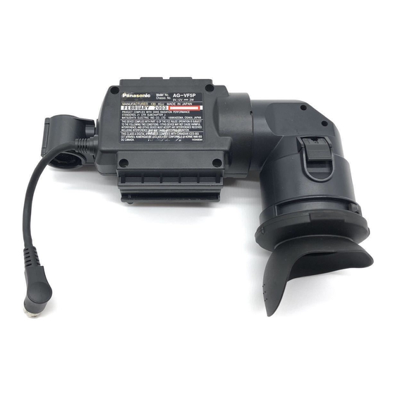
Summary of Contents for Panasonic AG-VF5P
- Page 1 ORDER NO. BSD0109M908 D20, D21 1.5"Electronic View Finder AG-VF5P/E/MC...
- Page 2 SAFETY PRECAUTIONS GENERAL GUIDELINES 1. When servicing, observe the original lead dress. If a short / circuit is found, replace all parts which have been over-heated or damaged by the short circuit. 2. After servicing, see to it that all the protective devices such as insulation barriers, insulation papers shields are properly installed.
- Page 3 The resistance value must be more than 5M Figure1 LEAKAGE CURRENT HOT CHECK (See Figure 1) 1. Plug the AC cord directly into the AC outlet. / Do not use an isolation transformer for this check. 2. Connect a 1.5k , 10W resistor, in parallel with a 0.15 capacitor, between each exposed metallic part on the set an a good earth ground such as a water pipe, as shown in Figure1.
- Page 4 1. Immediately before handling any semiconductor component or semiconductor-equipped assembly, drain off any electrostatic charge on your body by touching a known earth ground. / Alternatively, obtain and wear a commercially available discharging wrist trap device, which should be removed for potential shock reasons prior to applying power to the unit under test.
- Page 5 X-RADIATION WARNING 1. The potential source of X-radiation in EVF sets is the High Voltage section and the picture tube. 2. When using a picture tube test jig for service, ensure that jig is capable of handling 10kV without causing x-radiation. Note : It is important to use an accurate periodically calibrated high voltage meter.
- Page 6 NOTE BE SURE TO MAKE YOUR ORDERS OF REPLACEMENT PARTS ACCORDING TO PARTS LIST. CAUTION MARK INDICATES THE PRIMARY CIRCUIT TO DISTINGUISH THE PRIMARY FROM THE SECONDARY CIRCUIT. / PAY ATTENTION NOT TO RECEIVE AN ELECTRIC SHOCK DURING REPAIR SERVICE OF THE PRODUCTS. IMPORTANT SAFETY NOTICE: COMPONENTS IDENTIFIED WITH THE MARK HAVE THE SPECIAL CHARACTERISTICS FOR...
- Page 7 NOTE: 1. Be sure to make your orders of replacement parts according to this list. 2. Unless otherwise specified, all resistors are in OHMS, K=1,000 OHMS, all capacitors are in MICROFARADS F), P= 3. The P.C. Board untils marked with " "...
- Page 8 Components identified with the mark have the special characteristics for safety. When replacing any of these components, use only the same type. MECHANICAL COMPONENT ASSEMBLY Ref.No. Part No. Part Name & Description Remarks Ref.No. Part No. Part Name & Description Remarks M04KYS07WB ELY15V114G...
- Page 9 MECHANICAL COMPONENT ASSEMBLY PRT-2...
- Page 10 Ref . No. Part No. Part Name & Description Remarks Ref . No. Part No. Part Name & Description Remarks VQT9454 OPERATING INSTRUCTIONS 1 FOR AG-VF5P VQT9455 OPERATING INSTRUCTIONS 1 FOR AG-VF5E VQT9456 OPERATING INSTRUCTIONS 1 FOR AG-VF5MC VPN5665 VPF0210 POLYETHYLENE BAG...
- Page 11 ELECTRICAL REPLACEMENT PARTS LIST Ref.No. Part No. Part Name & Description Remarks Ref.No. Part No. Part Name & Description Remarks D9004 MA3047 DIODE VEP20869A CRT MASK C.B.A. 1 (RTL) IC9001 AN77L05M VEP20866A MAIN C.B.A. 1 (RTL) IC9002 TC7S04F 1 C0JBAB000169 IC9003 AN77L08M VEP20867A...
- Page 12 Ref.No. Part No. Part Name & Description Remarks Ref.No. Part No. Part Name & Description Remarks R9047 ERJ3GEY0R00 M.RESISTOR CH 1/16W R9217 ERJ6RED124 M.RESISTOR CH 1/10W 120K R9048-50 ERJ3RBD271 M.RESISTOR CH 1/16W 270 R9218 ERJ6RBD104 M.RESISTOR CH 1/10W 100K R9051 ERJ3GEYJ104 M.RESISTOR CH 1/16W 100K R9219...
- Page 13 Ref.No. Part No. Part Name & Description Remarks Ref.No. Part No. Part Name & Description Remarks R9424 ERJ6GEYF473 M.RESISTOR CH 1/10W 47K R9425,26 ERJ6GEYG105 M.RESISTOR CH 1/10W T9402 G4GXB0000001 FBT TG9401 EYF6CU TEST POINT TP9403-05 EYF6CU TEST POINT VR9401 VRV0113B200T V.RESISTOR VR9402 EVMLRGA00B16 V.RESISTOR VR9403...
- Page 14 ORDER NO. BSD0109M908 D20,D21 1.5” Electronic View Finder Sec. 1 Disassembly Procedures AG-VF5P/E/MC Sec. 2 Electrical Adjustments Sec. 3 Block Diagrams Sec. 4 Schematic Diagrams Sec. 5 Circuit Board Diagrams Sec. 6 Exploded Views & Replacement Parts List © 2001 Matsushita Electric Industrial Co., Ltd. All rights reserved.
- Page 15 Products powered by electricity should be serviced or repaired only by experienced professional technicans. Any attempt to service or repair the product or products deal with in this service manual by anyone else could result in serious injury or death. AG-VF5P AG-VF5E/MC...
- Page 16 SAFETY PRECAUTIONS GENERAL GUIDELINES ELECTROSTATICALLY SENSITIVE (ES) DEVICES 1. When servicing, observe the original lead dress. If a short Some semiconductor (solid state) devices can be damaged circuit is found, replace all parts which have been over- easily by static electricity. Such components commonly are heated or damaged by the short circuit.
-
Page 17: Table Of Contents
DISASSEMBLY PROCEDURES CONTENTS Removal of The Attachment Unit ..............DIS-1 Removal of The Mic Holder................DIS-1 Removal of The Eye Cap (rubber)..............DIS-1 Removal of The Eyepeace Ass’y (Eyepeace Holder)........DIS-1 Removal of The Top Case................. DIS-2 Removal of The CRT Ass’y ................DIS-2 <Caution when the installation of The CRT Ass’y>.......... -
Page 18: Removal Of The Attachment Unit
1. Removal of Attachment Unit 3. Removal of Eye Cap (rubber) 1. Loosen VF lock ring, and pull out VF lock ring to 1. Remove Eye Cap by turning over the portion (A). the direction of the arrow after loosening 1 screw Note: Be careful not to damage the rubber. -
Page 19: Removal Of The Top Case
Remove Lens Holder and Plate Spring from 5. Removal of Top Case Eyepiece Holder. 1. Loosen 4 screws (D), and then remove Top Case. Note: When installing, set Plate Spring into groove of Eyepiece Holder as shown in the figure, and 6. - Page 20 3. Loosen 4 screws (E), and then remove CRT case. Note: Remove CRT case so as not to drop the mirror installed in CRT case. Note: Be careful not to put any fingerprints on the mirror. 4. Remove anode cap from CRT. 5.
- Page 21 <Caution for the installation of the CRT Ass'y> Taping all lines in this place Green/Yellow line from CRT 25mm Red/ Blue line from CRT 35mm Gray line from CRT mask. The end of taping must be in this place. If there are lines that are too long, adjust by pulling toward the direction of the arrow.
- Page 22 <Lines binding completed figure at rotating eyepiece to downward> Tape this place. Tape at the root of anode cap (Coil 2 times). Fix red/blue lines from CRT by taping up the root of the lines. Then insert into connector of Rear C.B.A.
- Page 23 ELECTRICAL ADJUSTMENT CONTENTS 1. H HOLD Adjustment ........................EAD-1 2. V HOLD Adjustment ........................EAD-1 3. VIDEO +B Adjustment ....................... EAD-2 4. Sub Brightness Adjustment ....................EAD-2 5. Rotation Adjustment ......................... EAD-2 6. Centering Adjustment ....................... EAD-3 7. Picture Size Adjustment ......................
-
Page 24: H Hold Adjustment
Electrical Adjustment Procedures 1. H HOLD Adjustment <Recommended Measurement Equipment (M.EQ) & Servicing Fixtures> Board MAIN N o . N AM E M o d el R e m a r k EVF Screen D i g i t a l V o l t M e t e r Adjust VR9001 [H HOLD] F r e q u e n c y C o u n t e r... -
Page 25: Video +B Adjustment
3. VIDEO +B Adjustment 5. Rotation Adjustment Board FRONT, REAR Board ----- C9223 left side pin (FRONT board) EVF Screen Adjust VR9401 [VIDEO+B] (REAR board) Adjust Deflection Yoke Input Camera color bar Input Registration Chart M.EQ Digital Volt Meter M.EQ ----- Spec. -
Page 26: Centering Adjustment
6. Centering Adjustment 7. Picture Size Adjustment Board ----- Board MAIN EVF Screen EVF Screen Adjust Centering Magnet Adjust VR9004 [V SIZE] Input Registration Chart Input Registration Chart M.EQ ----- M.EQ ----- Spec. as shown in figure Spec. as shown in figure 1. -
Page 27: Balance Adjustment
9. Balance Adjustment 10. Focus Adjustment Board REAR Board MAIN EVF Screen EVF Screen Adjust Deflection Yoke Adjust VR9402 [FOCUS] Centering Magnet Input Registration Chart VR9003 [V LIN] M.EQ ----- VR9004 [V SIZE] Spec. Optimized resolution Input Registration Chart 1. Adjust VR9402 so that Resolution is optimized. M.EQ ----- Spec. - Page 28 BLOCK DIAGRAMS CONTENTS EVF BLOCK DIAGRAM ..................... BLK-1...
- Page 29 EVF BLOCK DIAGRAM BLK-1...
- Page 30 EVF BLOCK DIAGRAM BLK-1...
- Page 31 SCHEMATIC DIAGRAMS About indication of a circuit name Circuit Name COMPONENT Circuit Board No. F1:SERVO (CTL) NAME CIRCUIT BOARD NO. DRAWING NO. KR2D53 (1/17) VEP82230A-1 Drawing No. SCM001 Page No. NOTE: NOTE: BE SURE TO MAKE YOUR ORDERS OF REPLACEMENT PARTS ACCORDING TO PARTS LIST. DO NOT USE THE PART NUMBER SHOWN ON THIS DRAWING FOR ORDERING.
- Page 32 CONTENTS CRTMASK CRTMASK (1/1) ............ SCM1 MAIN MAIN (1/1)............. SCM2 FRONT FRONT (1/1) ............SCM3 REAR REAR (1/1)............SCM4 EVF INTERFACE EVF INTERFACE(1/1) .......... SCM5...
-
Page 33: Crtmask
COMPONENT CRTMASK 01/01 NAME CIRCUIT BOARD NO. DRAWING NO. KR0Q44 (1/1) VEP20869A SCM001... -
Page 34: Main (1/1)
COMPONENT MAIN 01/01 NAME CIRCUIT BOARD NO. DRAWING NO. IMPORTANT SAFETY NOTICE: COMPONENTS IDENTIFIED WITH THE MARK HAVE THE SPECIAL CHARACTERISTICS FOR SAFETY. WHEN REPLACING ANY OF THESE COMPONENTS, USE ONLY THE SAME TYPE. KR0Q41(1/1) VEP20866A SCM002... -
Page 35: Front
COMPONENT FRONT 01/01 NAME CIRCUIT BOARD NO. DRAWING NO. KR0Q42(1/1) VEP20867A SCM003... -
Page 36: Rear (1/1)
COMPONENT REAR 01/01 NAME IMPORTANT SAFETY NOTICE: DRAWING NO. COMPONENTS IDENTIFIED WITH THE MARK HAVE THE SPECIAL CHARACTERISTICS FOR SAFETY. CIRCUIT BOARD NO. WHEN REPLACING ANY OF THESE COMPONENTS, USE ONLY THE SAME TYPE. KR0Q43(1/1) VEP20868A SCM004... -
Page 37: Evf Interface
COMPONENT EVF INTERFACE 01/01 NAME IMPORTANT SAFETY NOTICE: CIRCUIT BOARD NO. DRAWING NO. COMPONENTS IDENTIFIED WITH THE MARK HAVE THE SPECIAL CHARACTERISTICS FOR SAFETY. WHEN REPLACING ANY OF THESE COMPONENTS, USE ONLY THE SAME TYPE. KR9K37(1/1) SCM005... - Page 38 CIRCUIT BOARD DIAGRAMS NOTE: NOTE: BE SURE TO MAKE YOUR ORDERS OF REPLACEMENT PARTS ACCORDING TO PARTS LIST. DO NOT USE THE PART NUMBER SHOWN ON THIS DRAWING FOR ORDERING. THE CORRECT PART NUMBER SHOWN IN THE PARTS LIST. AND MAY BE SLIGHTLY DIFERENT OR AMENDED SINCE THIS DRAWING WAS PREPARED. CAUTION MARK INDICATES THE PRIMARY CIRCUIT TO DISTINGUISH THE PRIMARY FROM THE SECONDARY CIRCUIT.
- Page 39 CRT MASK C.B.A. (VEP20869A) (FOIL SIDE) (COMPONENT SIDE) MAIN C.B.A. (VEP20866A) (FOIL SIDE) (COMPONENT SIDE) CBA-1...
- Page 40 FRONT C.B.A. (VEP20867A) (FOIL SIDE) (COMPONENT SIDE) REAR C.B.A. (VEP20868A) (FOIL SIDE) (COMPONENT SIDE) CBA-2...
- Page 41 EXPLODED VIEWS & REPLACEMENT PARTS LISTS Note: 1. *Be sure to make your orders of replacement parts according to this list. 2. Unless otherwise specified, all resistors are in OHMS, K=1,000 OHMS, all capacitors are in MICROFARADS (µF), P=µµF. 3. The P.C. Board untils marked with " " shown below the main assembled parts. 4.
- Page 42 Components identified with the mark have the special characteristics for safety. When replacing any of these components, use only the same type. MECHANICAL COMPONENT ASSEMBLY Ref.No. Part No. Part Name & Description Remarks Ref.No. Part No. Part Name & Description Remarks M04KYS07WB ELY15V114G...
- Page 43 MECHANICAL COMPONENT ASSEMBLY PRT-2...
- Page 44 Ref . No. Part No. Part Name & Description Remarks Ref . No. Part No. Part Name & Description Remarks VQT9454 OPERATING INSTRUCTIONS 1 FOR AG-VF5P VQT9455 OPERATING INSTRUCTIONS 1 FOR AG-VF5E VQT9456 OPERATING INSTRUCTIONS 1 FOR AG-VF5MC VPN5665 VPF0210 POLYETHYLENE BAG...
- Page 45 ELECTRICAL REPLACEMENT PARTS LIST Ref.No. Part No. Part Name & Description Remarks Ref.No. Part No. Part Name & Description Remarks D9004 MA3047 DIODE VEP20869A CRT MASK C.B.A. 1 (RTL) IC9001 AN77L05M VEP20866A MAIN C.B.A. 1 (RTL) IC9002 TC7S04F 1 C0JBAB000169 IC9003 AN77L08M VEP20867A...
- Page 46 Ref.No. Part No. Part Name & Description Remarks Ref.No. Part No. Part Name & Description Remarks R9047 ERJ3GEY0R00 M.RESISTOR CH 1/16W R9217 ERJ6RED124 M.RESISTOR CH 1/10W 120K R9048-50 ERJ3RBD271 M.RESISTOR CH 1/16W 270 R9218 ERJ6RBD104 M.RESISTOR CH 1/10W 100K R9051 ERJ3GEYJ104 M.RESISTOR CH 1/16W 100K R9219...
- Page 47 Ref.No. Part No. Part Name & Description Remarks Ref.No. Part No. Part Name & Description Remarks R9424 ERJ6GEYF473 M.RESISTOR CH 1/10W 47K R9425,26 ERJ6GEYG105 M.RESISTOR CH 1/10W T9402 G4GXB0000001 FBT TG9401 EYF6CU TEST POINT TP9403-05 EYF6CU TEST POINT VR9401 VRV0113B200T V.RESISTOR VR9402 EVMLRGA00B16 V.RESISTOR VR9403...
- Page 48 1. Removal of Attachment Unit 3. Removal of Eye Cap (rubber) 1. Loosen VF lock ring, and pull out VF lock ring to 1. Remove Eye Cap by turning over the portion (A). the direction of the arrow after loosening 1 screw Note: Be careful not to damage the rubber.
- Page 49 Remove Lens Holder and Plate Spring from 5. Removal of Top Case Eyepiece Holder. 1. Loosen 4 screws (D), and then remove Top Case. Note: When installing, set Plate Spring into groove of Eyepiece Holder as shown in the figure, and 6.
- Page 50 3. Loosen 4 screws (E), and then remove CRT case. Note: Remove CRT case so as not to drop the mirror installed in CRT case. Note: Be careful not to put any fingerprints on the mirror. 4. Remove anode cap from CRT. 5.
- Page 51 <Caution for the installation of the CRT Ass'y> Taping all lines in this place Green/Yellow line from CRT 25mm Red/ Blue line from CRT 35mm Gray line from CRT mask. The end of taping must be in this place. If there are lines that are too long, adjust by pulling toward the direction of the arrow.
- Page 52 <Lines binding completed figure at rotating eyepiece to downward> Tape this place. Tape at the root of anode cap (Coil 2 times). Fix red/blue lines from CRT by taping up the root of the lines. Then insert into connector of Rear C.B.A.
- Page 53 Electrical Adjustment Procedures 1. H HOLD Adjustment <Recommended Measurement Equipment (M.EQ) & Servicing Fixtures> Board MAIN N o . N AM E M o d el R e m a r k EVF Screen D i g i t a l V o l t M e t e r Adjust VR9001 [H HOLD] F r e q u e n c y C o u n t e r...
- Page 54 3. VIDEO +B Adjustment 5. Rotation Adjustment Board FRONT, REAR Board ----- C9223 left side pin (FRONT board) EVF Screen Adjust VR9401 [VIDEO+B] (REAR board) Adjust Deflection Yoke Input Camera color bar Input Registration Chart M.EQ Digital Volt Meter M.EQ ----- Spec.
- Page 55 6. Centering Adjustment 7. Picture Size Adjustment Board ----- Board MAIN EVF Screen EVF Screen Adjust Centering Magnet Adjust VR9004 [V SIZE] Input Registration Chart Input Registration Chart M.EQ ----- M.EQ ----- Spec. as shown in figure Spec. as shown in figure 1.
- Page 56 9. Balance Adjustment 10. Focus Adjustment Board REAR Board MAIN EVF Screen EVF Screen Adjust Deflection Yoke Adjust VR9402 [FOCUS] Centering Magnet Input Registration Chart VR9003 [V LIN] M.EQ ----- VR9004 [V SIZE] Spec. Optimized resolution Input Registration Chart 1. Adjust VR9402 so that Resolution is optimized. M.EQ ----- Spec.
- Page 57 EVF BLOCK DIAGRAM BLK-1...
- Page 58 COMPONENT CRTMASK 01/01 NAME CIRCUIT BOARD NO. DRAWING NO. KR0Q44 (1/1) VEP20869A SCM001...
- Page 59 COMPONENT MAIN 01/01 NAME CIRCUIT BOARD NO. DRAWING NO. IMPORTANT SAFETY NOTICE: COMPONENTS IDENTIFIED WITH THE MARK HAVE THE SPECIAL CHARACTERISTICS FOR SAFETY. WHEN REPLACING ANY OF THESE COMPONENTS, USE ONLY THE SAME TYPE. KR0Q41(1/1) VEP20866A SCM002...
- Page 60 COMPONENT FRONT 01/01 NAME CIRCUIT BOARD NO. DRAWING NO. KR0Q42(1/1) VEP20867A SCM003...
- Page 61 COMPONENT REAR 01/01 NAME IMPORTANT SAFETY NOTICE: DRAWING NO. COMPONENTS IDENTIFIED WITH THE MARK HAVE THE SPECIAL CHARACTERISTICS FOR SAFETY. CIRCUIT BOARD NO. WHEN REPLACING ANY OF THESE COMPONENTS, USE ONLY THE SAME TYPE. KR0Q43(1/1) VEP20868A SCM004...
- Page 62 COMPONENT EVF INTERFACE 01/01 NAME IMPORTANT SAFETY NOTICE: CIRCUIT BOARD NO. DRAWING NO. COMPONENTS IDENTIFIED WITH THE MARK HAVE THE SPECIAL CHARACTERISTICS FOR SAFETY. WHEN REPLACING ANY OF THESE COMPONENTS, USE ONLY THE SAME TYPE. KR9K37(1/1) SCM005...
- Page 63 CRT MASK C.B.A. (VEP20869A) (FOIL SIDE) (COMPONENT SIDE) MAIN C.B.A. (VEP20866A) (FOIL SIDE) (COMPONENT SIDE) CBA-1...
- Page 64 FRONT C.B.A. (VEP20867A) (FOIL SIDE) (COMPONENT SIDE) REAR C.B.A. (VEP20868A) (FOIL SIDE) (COMPONENT SIDE) CBA-2...