Table of Contents
Advertisement
Quick Links
Indoor Pan/Tilt Head
Pan/Tilt Control Panel
Cable Compensation Unit
Roll Unit
AW-PH400
AW-RC400
Before attempting to connect, operate or adjust this product,
Before attempting to connect, operate or adjust this product,
please read these instructions completely.
please read these instructions completely.
AW-PH400P
AW-RP400N
AW-RC400N
AW-RL400G
AW-RP400
AW-RL400
Advertisement
Table of Contents

Related Manuals for Panasonic AW-RC400N


Summary of Contents for Panasonic AW-RC400N
- Page 1 Cable Compensation Unit Roll Unit AW-PH400 AW-RC400 Before attempting to connect, operate or adjust this product, Before attempting to connect, operate or adjust this product, please read these instructions completely. please read these instructions completely. AW-PH400P AW-RP400N AW-RC400N AW-RL400G AW-RP400 AW-RL400...
-
Page 2: Safety Precautions
Safety precautions CAUTION RISK OF ELECTRIC SHOCK DO NOT OPEN CAUTION: TO REDUCE THE RISK OF ELECTRIC SHOCK, DO NOT REMOVE COVER (OR BACK). NO USER SERVICEABLE PARTS INSIDE. REFER SERVICING TO QUALIFIED SERVICE PERSONNEL. The lightning flash with arrowhead symbol, within an equilateral triangle, is intended to alert the user to the presence of uninsulated “dangerous voltage”... -
Page 3: Important Safety Instructions
Safety precautions IMPORTANT SAFETY INSTRUCTIONS Read these operating instructions carefully before using the unit. Follow the safety instructions on the unit and the applicable safety instructions listed below. Keep these operating instructions handy for future reference. 1) Read these instructions. 2) Keep these instructions. -
Page 4: Table Of Contents
Contents Safety precautions ... 2 Operating precautions ... 5 AW-PH400 Indoor Pan/Tilt Head... 6 Introduction ... 6 Accessories ... 6 Precautions for use ... 6 Installation precautions ... 7 Parts and their function ... 8 Installation ... 12 $ Assembling the pan/tilt head ... 12 $ Setting the mounting direction switch ... -
Page 5: Operating Precautions
Operating precautions ≥ Handle the units carefully. Dropping the units or subjecting them to strong impact may give rise to malfunctioning or accidents. ≥ Turn off the power before connecting or disconnecting the cables. Be absolutely sure to turn off the power before connecting or disconnecting the cables. ≥... -
Page 6: Aw-Ph400 Indoor Pan/Tilt Head
Indoor Pan/Tilt Head AW-PH400 Introduction ≥ The stand-alone indoor pan/tilt head can be rotated through 300 degrees in the vertical direction and 400 degrees in the horizontal direction. ≥ Operations can be performed at high speeds of up to 90 degrees per second. ≥... -
Page 7: Installation Precautions
Installation precautions ≥ Do not install the unit on any of its sides. ≥ Avoid using the unit in the kitchen and other locations with lots of steam and oily vapors. ≥ Mount the camera on the pan/tilt head only when you have finished installing it. ≥... -
Page 8: Parts And Their Function
Indoor Pan/Tilt Head AW-PH400 Parts and their function < >... - Page 9 Parts and their function Rotary head connector panel 1 Rotary head This rotates in the horizontal direction. 2 Pedestal 3 POWER ON/OFF switch When this is set to ON, the unit’s power is turned on; when it is set to OFF, it is turned off. 4 AC 120 inlet [AC IN] (AC 3-point inlet) Connect the accessory AC power cable to this inlet.
- Page 10 Indoor Pan/Tilt Head AW-PH400 Parts and their function = Guide pin Use this to determine the direction in which the camera is to be mounted. > Camera mounting screws (U1/4” 20UNC) These are used to secure the camera firmly after it has been mounted.
- Page 11 Parts and their function J Y connector [Y] This is the output connector for the camera’s video signals. It is connected to the Y/VIDEO connector on the AW-RC400 cable compensation unit or monitor, etc. Use a BNC coaxial cable for the connecting cable. The AW-PB302 RGB card must be installed if the AW-E300, AW-E300A, AW-E600, AW-E800 or AW-E800A convertible camera is to be used.
-
Page 12: Installation
Indoor Pan/Tilt Head AW-PH400 Installation (Be sure to ask your dealer to install the unit.) $ Assembling the pan/tilt head When assembling the pan/tilt head, use the Allen key (provided) and screwdriver, and secure the head by tightening the screws firmly. - Page 13 Installation (Be sure to ask your dealer to install the unit.) 3 Mounting the tally lamp Connect the cable connector which is taped to the top of the pan/tilt head to the tally lamp connector. Mount the tally lamp on the top of the pan/tilt head using the two screws provided. Mount the lamp while paying attention to the wire.
-
Page 14: Setting The Mounting Direction Switch
Indoor Pan/Tilt Head AW-PH400 Installation (Be sure to ask your dealer to install the unit.) $ Setting the mounting direction switch Set the switch as follows when the unit is to be installed on the ceiling. (This switch was set to the stand-alone installation position at the factory.) 1 Remove the four screws, and gently remove the pedestal connector panel. -
Page 15: Setting The Pcb Switches
Installation (Be sure to ask your dealer to install the unit.) $ Setting the PCB switches The switches on the CONNECTOR PCB will need to be set in accordance with the signals to be transmitted and the equipment to be connected to the pan/tilt head. (The switches are set to support analog/SDI at the factory.) ≥... -
Page 16: Installing The Pan/Tilt Head
Indoor Pan/Tilt Head AW-PH400 Installation (Be sure to ask your dealer to install the unit.) $ Installing the pan/tilt head When installing the pan/tilt head, follow the instructions below carefully. In order to prevent accidents resulting when the product becomes dislodged or falls down, be absolutely sure to proceed as instructed. -
Page 17: Mounting The Camera
Installation (Be sure to ask your dealer to install the unit.) $ Mounting the camera When mounting the camera on the pan/tilt head, be very careful to ensure that the camera does not fall off or fall down. 1 Mount the lens onto the convertible camera. (Before mounting a large lens, consult with your dealer.) 2 Insert the rubber piece between the camera and pan/tilt head, and mount the convertible camera after aligning it with the guide pins. -
Page 18: Attaching The Wire
Indoor Pan/Tilt Head AW-PH400 Installation (Be sure to ask your dealer to install the unit.) $ Attaching the wire The wire is not provided. Use one which is strong enough to bear the weight of the whole camera (camera + lens). When mounting the cameras with fan (AW-E655, AW-E750, AW-E800, AW-E800A) 1 Use the wire mounting screw (M4!8 mm with flat washer and spring washer) to attach one end of the wire to the pan/tilt head’s arm. -
Page 19: Replacing The Consumable Parts
Replacing the consumable parts $ Replacing the battery The battery has a service life of approximately 5 years. The unit stores the preset positions, limiters and other data in its memory. This data is retained even when the power is turned off, but if the internal battery has reached the end of its service life, the data will be lost when the power is turned off. -
Page 20: Specifications
Indoor Pan/Tilt Head AW-PH400 Specifications Supply voltage: AC 120 V, 60 Hz Power consumption: 145 W 1 indicates safety information. Genlock input: Prompter input (PROMPTER IN): Prompter output (PROMPTER OUT): Camera video output VIDEO: Pr/C: SDI: Camera, pan/tilt head control: RP/IP Functions/performance: Ambient operating temperature: 32°F to 113°F (0°C to +45°C) - Page 21 MEMO...
-
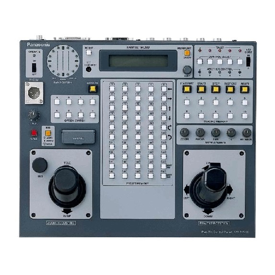
Page 22: Aw-Rp400 Pan/Tilt Control Panel
Pan/Tilt Control Panel AW-RP400 Introduction ≥ This pan/tilt control panel enables up to five AW-PH400 indoor pan/tilt heads to be controlled. ≥ By connecting the AW-CB400 remote operation panel or WV-CB700A remote control box to the control panel, the convertible cameras mounted on the pan/tilt heads can be controlled at the same time. -
Page 23: Parts And Their Function
Parts and their function $ Front panel < > 1 EXT CONT [M/S] switch This switch is normally kept at the [M] (master) position. When an additional AW-RP400 control panel has been installed, set the EXT CONT switch on the additional unit to [S] (slave). - Page 24 Pan/Tilt Control Panel AW-RP400 Parts and their function 7 IRIS [AUTO/MANU/LOCK] button Use this to select the method for adjusting the lens iris of the cameras in the currently selected pan/tilt head system. Each time it is pressed, the setting is switched in the sequence of AUTO, MANU and LOCK.
- Page 25 Parts and their function B MEMORY button When one of the (C) PRESET MEMORY selection buttons [1] to [50] is pressed while holding down the MEMORY button, the settings of the pan/tilt head system can be registered in that PRESET MEMORY selection button.
-
Page 26: Rear Panel
Pan/Tilt Control Panel AW-RP400 Parts and their function $ Rear panel M EXT CONT IN/OUT connectors When an additional AW-RP400 control panel is to be provided, connect these connectors on the two AW-RP400 control panels using a 10BASE-T (equivalent to UTP category 5) straight cable. Master control panel AW-RP400... - Page 27 Parts and their function P REMOTE connector Connect an external unit to this connector to control the pan/tilt head systems from a PC or other external unit. Connect the connector to the PC using the AW-CA50T9 RS-232C cable. Q DC 12V IN socket Connect the AW-PS505 AC adaptor (sold separately) to this socket.
-
Page 28: Menu Settings
Pan/Tilt Control Panel AW-RP400 Menu settings $ Operation method 1 The menu setting items are displayed when the MENU/LIMIT switch is held down for two or more seconds. 2 If nothing appears on the bottom line of the LCD display, turn the CONT dial to select a menu item. -
Page 29: List Of Menu Items And Settings
Menu settings $ List of menu items and settings Menu item PRIORITY DIRECTION TILT ZOOM FOCUS IRIS ROTATION TILT RANGE SPEED WITH ZOOM POS. MEMORY LENGTH PRESET SPEED IRIS CONTROL ROTATION SWITCH OPTION SWITCH CONTROL SELECT MODE BUZZER AUTO RUN START No. - Page 30 Pan/Tilt Control Panel AW-RP400 Menu settings DIRECTION settings (PAN, TILT, ZOOM, FOCUS, IRIS, ROTATION: NORMAL/REVERSE) When the lever or dial is operated, the DIRECTION menu item enables the operational direction of PAN, TILT, ZOOM, FOCUS, IRIS or ROTATION to be set as the user desires. PAN: When NORMAL is selected, the pan/tilt head moves toward the left when the PAN/TILT lever is tilted to the LEFT and toward the right when it is tilted to the RIGHT.
- Page 31 Menu settings OPTION SWITCH A to H settings (NOT USE / DEF / WIP / HEATER/FAN / LAMP / OPTION / ND / EXT / AF) The following functions can be allocated to OPTION buttons A to H. Different functions can be allocated for different pan/tilt heads.
- Page 32 Pan/Tilt Control Panel AW-RP400 Menu settings CONTROL SELECT MODE setting (INTERLOCK/UN-INTERLOCK) This menu item is for selecting the method used to select the pan/tilt head and camera when the AW-CB400 remote operation panel has been connected to the AW-RP400 control panel. INTERLOCK: When the pan/tilt head and camera system are selected by the AW-RP400 or AW-CB400, the same system is selected by the other unit as well.
-
Page 33: How To Mount The Aw-Rp400 In A Rack
How to mount the AW-RP400 in a rack <NOTE> ≥ The AW-RP400 is 320 mm wide. If it is to be installed in a full-size rack (which accommodates units totaling 420 mm in width), provide panels or other parts to supplement the AW-RP400’s width so that it will fill the rack width-wise. -
Page 34: How To Change The Position Of The Connector Panel
Pan/Tilt Control Panel AW-RP400 How to change the position of the connector panel The position of the connector panel can be changed from the rear panel to the bottom panel. Before changing the position, turn off the power. 1 Remove the five bottom panel screws, and remove the blank panel. -
Page 35: How To Replace The Zoom Switch
How to replace the zoom switch Before replacing the zoom switch, turn off the power. 1 Remove the four screws that secure the zoom lever. 2 Pull out the zoom lever, disconnect the two cables from the circuit board inside, and remove the zoom lever. 3 Plug the two cables extending from the zoom switch into the connectors on the circuit board inside. -
Page 36: Replacing The Consumable Parts
Pan/Tilt Control Panel AW-RP400 Replacing the consumable parts The joysticks and zoom switch are consumables. Replace them if they are not working properly. Ask your dealer to do the replacement work. -
Page 37: Specifications
Specifications Supply voltage: DC 12.0 V Power consumption: Approx. 13 W 1 indicates safety information. Input connectors DC 12V IN: XLR, 4 pins CONTROL IN FROM ROP: D-SUB 29-pin, cable supplied with AW-CB400 remote operation panel CONTROL IN FROM RCB: 10-pin round connector, cable supplied with WV-CB700A EXT CONT IN: RJ45, additional AW-RP400 control signal input;... -
Page 38: Aw-Rc400 Cable Compensation Unit
Cable Compensation Unit AW-RC400 Introduction ≥ The AW-RC400 is capable of providing cable compensation for analog composite, analog Y/C or analog component signals in five channels up to 500 meters (when the BELDEN 8281 connecting cable or its equivalent is used). ≥... -
Page 39: Parts And Their Function
Parts and their function 1 2 3 45 Front panel 1 Power LED This lights up green when the (2) POWER switch is set to ON while a DC 12V voltage is supplied to the (7) DC 12V IN socket. 2 POWER switch Set this to ON to turn on the cable compensation unit’s power. - Page 40 Cable Compensation Unit AW-RC400 Parts and their function ; MONITOR1, 2 connectors The video signals of the cameras selected by the AW-RP400 pan/tilt control panel or the AW-CB400 remote operation panel which is connected to the AW-RP400 are output from these connectors. The output signals are cable-compensated signals of the same type as the input signals.
-
Page 41: How To Mount The Aw-Rc400 In A Rack
How to mount the AW-RC400 in a rack Use the accessory rack-mounting adaptors and accessory mounting screws (M4!8 mm) to mount the unit in a rack. 1 Set the POWER switch at the OFF position to turn off the power. 2 Remove four feet on the bottom of the unit. -
Page 42: Specifications
Cable Compensation Unit AW-RC400 Specifications Supply voltage: DC 12.0 V Power consumption: Approx. 9 W 1 indicates safety information. Input connectors DC 12V IN: G/L IN: VIDEO/Y, Pr/C, Pb: MONI SEL IN: Output connectors G/L OUT: VIDEO/Y, Pr/C, Pb: MONITOR OUT1/2: Switch and adjustment functions: Power ON/OFF;... -
Page 43: Aw-Rl400 Roll Unit
Introduction ≥ The AW-RL400 roll unit enables a camera to be rotated when it is used in combination with the AW-PH400 indoor pan/tilt head. Accessories Pan/tilt head connecting cable ... 1 NOTE ≥ Since the roll unit causes the camera to rotate, the user should ensure that all the wiring such as the camera cable and lens cable will not become entangled when the roll unit is operated. -
Page 44: Parts And Their Function
Roll Unit AW-RL400 Parts and their function 1 Rotary ring 2 Camera mounting screw (U1/4”-20UNC) After mounting the camera, secure it firmly using this screw. 3 Camera mounting plate (A) (B) Mount the camera on this plate using the camera mounting screws. -
Page 45: Installation
Installation 1 Attach the pan/tilt head’s rotary arm to the roll unit using the three mounting screws (M5!22 mm, with flat washers, pan/tilt head accessory). 2 Attach the rotary arm to the pan/tilt head using the mounting screws (M5!22 mm, with flat washers, pan/tilt head accessory). 3 Loosen the two screws of camera mounting plate which is already installed to the roll unit. - Page 46 Roll Unit AW-RL400 Installation 4 Separate the camera mounting plate, which was removed in step 3, into its two sub plates. ≥ Separate the camera mounting plate into sub plate (A) and sub plate (B) by loosening the clamping screw. 5 Follow the steps below to mount the camera mounting sub plates, which were separated in step 4, onto the camera body.
- Page 47 Installation 6 Attach the camera mounting plate to the roll unit in a way contrary to the procedure of removing it in step 3. Camera mounting plate’s screws 7 Using the pan/tilt head connecting cable provided, connect the [OPTION] connector on the pan/tilt head connector panel and the connector on the roll unit.
-
Page 48: Specifications
Roll Unit AW-RL400 Specifications Supply voltage: DC 24 V Power consumption: Approx. 24 W 1 indicates safety information. Pan/tilt head connector: Performance: Ambient operating temperature: 32°F to 113°F (0°C to +45°C) Storage temperature: Ambient operating humidity: Dimensions (W!H!D): Weight: Finish: Weight and Dimensions indicated above are approximate. -
Page 49: Connections
Connections ≥ Turn off the power of all the equipment before proceeding with the connections. ≥ Use the AW-PS505 as the AC adaptor for the AW-RP400 pan/tilt control panel. Use the DC cable supplied with the AW-PS505 to connect the DC 12V IN socket on the AW-RP400 with the DC 12V OUT socket on the AW-PS505. - Page 50 Connections AW-CB400 Remote Operation Panel Cable supplied with AW-CB400 (AW-CB400 power and camera control signals) Monitor for AW-RP400 Monitor for AW-CB400 Motorized zoom lens AW-PH400 Indoor Pan/Tilt Head Pan/tilt head/camera control signals AC power cable supplied with AW-PH400 AW-RC400 Cable AW-RP400 Compensation Unit Pan/tilt control panel...
-
Page 51: Example Of System Configuration
Example of system configuration Convertible camera Indoor Pan/Tilt Head AW-PH400 Composite video or component video signals To switcher, monitor Genlock signals AW-RC400 AW-PS301 Cable Compensation AC adaptor Unit AW-PS505 AC adaptor MONITOR1 Monitor Monitor switching Cable provided with AW-CB400 Headset Pan/Tilt Control Panel AW-RP400 Pan/tilt head and camera control... -
Page 52: Operating Procedures
Operating procedures $ Turning on the power 1 When using one AW-RP400, set its EXT CONT [M/S] switch to the [M] position. When two AW-RP400 units are used, set the EXT CONT [M/S] switch on the AW-RP400 to which the pan/tilt head is connected to the [M] (master) position and the switch on the AW-RP400 to which the pan/tilt head is not connected to the [S] (slave) position. - Page 53 Operating procedures 6 To set the counterclockwise limit of the roll unit, use the ROTATION switch to rotate the roll unit as far as the limit in the counterclockwise direction which is to be set. While holding down the MENU/LIMIT button, press the PRESET MEMORY button [25]. Once the limit is set, the lamp of the PRESET MEMORY button [45] will light.
- Page 54 Operating procedures $ Genlock adjustments for the respective cameras For details on the genlock adjustments, refer to the operating instructions of the AW-CB400 remote operation panel or WV-CB700A remote control box. $ Video adjustments for the cameras Adjust the total pedestal (black level), white balance, black balance, etc. of the cameras. For details on the camera adjustments, refer to the operating instructions of the AW-CB400 remote operation panel or WV-CB700A remote control box.
- Page 55 Operating procedures 3 Press the START POINT button. The lamps of the buttons among TRACING MEMORY buttons 1 to 10 where data can be registered now light. ≥ The lamps of the buttons with numbers exceeding the number of memories set by the MEMORY LENGTH menu setting do not light.
- Page 56 Operating procedures Changing the tracing memory data 1 Select the pan/tilt head system using one of the CONTROL SELECT buttons. When using the AW-CB400 for camera control, select the same number for the AW-CB400. 2 Press the button corresponding to the tracing memory whose registered data is to be changed, and call the start position. 3 Press the RESTORE button.
- Page 57 Operating procedures Playing the preset memory data 1 Select the pan/tilt head system using one of the CONTROL SELECT buttons. 2 When the button corresponding to the registered preset memory data is pressed, the pan/tilt head system is set to the registered status.
-
Page 58: Cable Specifications
Cable specifications... - Page 59 Cable specifications...
- Page 60 Cable specifications...
- Page 64 PANASONIC BROADCAST & TELEVISION SYSTEMS COMPANY UNIT COMPANY OF PANASONIC CORPORATION OF NORTH AMERICA Executive Office: One Panasonic Way 4E-7, Secaucus, NJ 07094 (201) 348-7000 EASTERN ZONE: One Panasonic Way 4E-7, Secaucus, NJ 07094 (201) 348-7621 Southeast Region: 1225 Northbrook Parkway, Ste 1-160, Suwanee, GA 30024 (770) 338-6835...