
Related Manuals for Panasonic AW-PH360N


Summary of Contents for Panasonic AW-PH360N
- Page 1 Indoor Pan/Tilt Head AW-PH360N Before attempting to connect, operate or adjust this product, please read these instructions completely. Printed in Japan F0505Y0 VQTB0085...
- Page 2 CAUTION: TO REDUCE THE RISK OF ELECTRIC SHOCK, REFER TO SERVICING TO QUALIFIED SERVICE PERSONNEL. The lightning flash with arrowhead symbol, within an equilateral triangle, is intended to alert the user to the presence of uninsulated “dangerous voltage” within the product’s enclosure that may be of sufficient magnitude to constitute a risk of electric shock to persons.
- Page 3 FCC Note: This device complies with Part 15 of the FCC Rules. To assure continued compliance follow the attached installation instructions and do not make any unauthorized modifications. This equipment has been tested and found to comply with the limits for a class A digital device, pursuant to Part 15 of the FCC Rules.
-
Page 4: Table Of Contents
Contents Introduction ... 4 Accessories ... 4 Installation precautions ... 5 Precautions for use ... 6 Parts and their functions ... 7 Installation ... 9 $ Assembling the pan/tilt head ... 9 $ Controller selection switch / installation direction switch / landing characteristics settings . -
Page 5: Installation Precautions
Installation precautions O Do not install the pan/tilt head on any of its sides. OAvoid using the pan/tilt head in kitchens or other places where there is excessive steam and oil fumes. OMake sure that the installation of the pan/tilt head has been completed before mounting the camera onto it. -
Page 6: Precautions For Use
Precautions for use OIn order to protect the environment when the pan/tilt head is to be discarded at the end of its service life, ask a specialized contractor to dispose of it properly. OThis pan/tilt head uses a manganese dioxide-lithium battery (CR2032). Be absolutely sure to remove this battery when disposing of the pan/tilt head or printed circuit boards. -
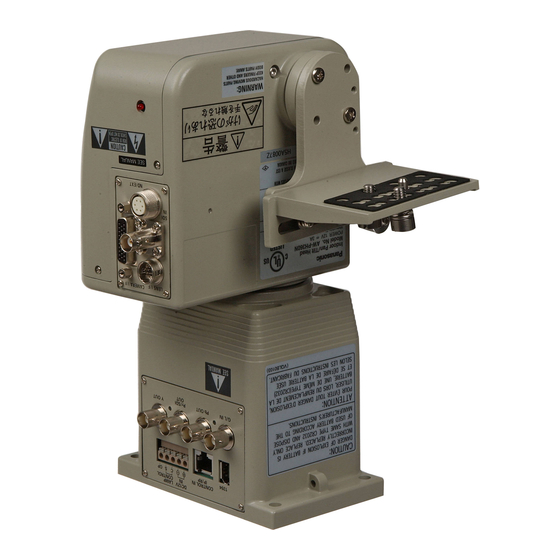
Page 7: Parts And Their Functions
Parts and their functions - 7 -... - Page 8 Parts and their functions 1 Tilting arm This tilts in the vertical direction. 2 Tilting arm fixing screws M4!12 mm (4 screws supplied) 3 Camera mounting plate This is used to mount the convertible camera. 4 Guide screws These are used to maintain the camera’s balance and anchor the camera mounting plate.
-
Page 9: Installation
Installation (The installation work must be performed by your dealer without fail.) $ Assembling the pan/tilt head Be absolutely sure to hold the pan/tilt head by the base when handling it. O Attaching the tilting arm Use the tilting arm fixing screws to attach the tilting arm. The way in which the arm is mounted differs depending on the direction in which it is installed. -
Page 10: Landing Characteristics Settings
Installation (The installation work must be performed by your dealer without fail.) $ Controller selection switch / installation direction switch / landing characteristics settings The following switches are set when determining controller selections, stand alone settings and landing characteristics settings. (RP501 / suspended installation / soft landing are the default settings.) 1. -
Page 11: Transmission Signal Selection Setting
Installation (The installation work must be performed by your dealer without fail.) $ Transmission signal selection setting The switches on the COMP and CONNECTOR printed circuit boards must be set to correspond to the signals to be transmitted and components to be connected to the pan/tilt head. -
Page 12: Setting The Cable Compensation Circuit Of Video Signals
Installation (The installation work must be performed by your dealer without fail.) $ Setting the cable compensation circuit of video signals (COMP switch of the COMP printed circuit board is set to “OFF” in the default setting.) 1 When using the AW-RP501 controller or the AW-HB505 multiport hub (for transmissions using composite signals) When this controller (or multiport hub) has been connected to the pan/tilt head, it is permissible for the connecting cables to be up to 1640 ft. -
Page 13: Installing The Pan/Tilt Head
Installation (The installation work must be performed by your dealer without fail.) $ Installing the pan/tilt head Be absolutely sure to follow the instructions below when installing the pan/tilt head. Failure to do so may cause the pan/tilt head to slip out of position or fall. OFor wall Do not install the pan/tilt head on any of its sides. -
Page 14: Mounting The Camera
Installation (The installation work must be performed by your dealer without fail.) $ Mounting the camera The pan/tilt head’s camera mounting section has a mechanism for maintaining the camera’s balance that moves the camera mounting plate using a guide roller as a fulcrum. Use the described recommended lenses corresponding to the camera to be used. - Page 15 Installation (The installation work must be performed by your dealer without fail.) • Stand-alone installation <Mounting example: when the camera side is heavy> <Mounting example: when the lens side is heavy> When the pan/tilt head is set at suspended installation, change the position of guide screws and guide pin B to adjust the balance as well as the stand-alone...
- Page 16 Installation (The installation work must be performed by your dealer without fail.) O Attaching the chain 1. Attach one end of the chain to the pan/tilt head using a chain attachment screw (M4!8 mm: with flat washer/spring washer). 2. Position the other end of the chain over the screw hole on the top of the camera and attach it using a chain attachment screw (M4!6 mm: with flat...
- Page 17 Installation (The installation work must be performed by your dealer without fail.) O Mounting a camera When mounting a camera to the pan/tilt head, take appropriate measures to prevent the camera from falling or being stolen. 1. Place the camera on the camera mounting base and insert the guide pin into the guide hole on the camera.
-
Page 18: Camera Cable
Connections $ Connecting the connector panel Zoom lens Control panel: AW-RP501 Coaxial cable Coaxial cable (BELDEN 8281) Monitor (with the controller AW-RP501) Head connector panel 10BASE-T (equivalent to UTP category 5) straight cable AC adapter: AW-PS505A Base connector front panel - 18 - Convertible camera Camera cable... - Page 19 Connections $ Connecting the connector panel Zoom lens Control panel: AW-RP505 Preview monitor (with the controller AW-RP505) Base connector front panel AC adapter: AW-PS505A Coaxial cable (BELDEN 8281) Monitor - 19 - Convertible camera Camera cable (supplied) DC cable (UL Type SPT-2 2!16 AWG or UL Type NISPT-2 2!16 AWG, to be locally purchased)
- Page 20 Connections $ Connecting the connector panel Zoom lens 10BASE-T (equivalent to UTP category 5) straight cable Coaxial cable (BELDEN 8281) Multi-Function Controller: AW-RP605A (with the controller AW-RP605A) Coaxial cable Monitor - 20 - Convertible camera Camera cable (supplied) DC cable (UL Type SPT-2 2!16 AWG or UL Type NISPT-2 2!16 AWG, to be locally...
- Page 21 Connections $ Connecting the connector panel Zoom lens 10BASE-T (equivalent to UTP category 5) straight cable AW-CB400 AW-RP400 Remote operation Pan/tilt control panel panel Cable supplied with AW-CB400 (AW-CB400 power and camera control signals) Monitor for AW-RP400 Monitor for AW-CB400 (with the controller AW-RP400) Base connector front panel...
- Page 22 Connections $ Connecting the connector panel Zoom lens RS-232C cable: AW-CA28T9 • The BNC connectors are not connected to the pan/tilt head. • When using RS-232C for control, the maximum length of the RS-232C cable is 50 ft. (15 m). To further extend the cable length, convert RS-232C to RS-422 and convert it back to RS-232C at the...
-
Page 23: Head Connector Panel
Connections $ Head connector panel The camera and lens control cables are connected to this panel. 1 ND/EXT connector This is for controlling the ND filter and lens extender of the power lens unit. Connect it when using a power lens unit equipped with an ND filter and lens extender function. -
Page 24: Connecting The Base Connector Rear Panel And The Base Connector Front Panel
Connections $ Connecting the base connector rear panel and the base connector front panel 5 1394 connector This is for controlling the convertible camera, in which an IEEE 1394 card has been installed, and the pan/tilt head. As the connecting cable, use an IEEE 1394 cable. - Page 25 Connections 9 Pb OUT connector This is for camera video signal output. Connect this to the Pb IN connector on the controller or to a monitor, etc. Use a coaxial cable (BELDEN 8281) for the connecting cable. : G/L IN connector This is for genlock signal input.
-
Page 26: Connecting The Ac Adapter For Use With The Pan/Tilt Head
Connections $ Connecting the AC adapter for use with the pan/tilt head Connect the pan/tilt head with the AW-PS300A AC adapter designed for use with the pan/tilt head. > DC 12V IN terminal board Connect this to the DC 15V OUT connector on the AC adapter (AW-PS300A). -
Page 27: Connection Examples
Connections $ Connection examples 1When the camera and pan/tilt head are to be controlled by the AW-RP501 control panel for transmitting composite signals DC cable (UL Type SPT-2 2!16 AWG or UL Type NISPT-2 2!16 AWG, to be locally purchased) 10BASE-T (equivalent to UTP AC adapter:... - Page 28 Connections 2When the camera and pan/tilt head are to be controlled by the AW-RP501 control panel for transmitting component signals DC cable (UL Type SPT-2 2!16 AWG or UL Type NISPT-2 2!16 AWG, to be locally purchased) 10BASE-T (equivalent to UTP category 5) straight AC adapter: cable, max.
- Page 29 Connections 3When the camera and pan/tilt head are to be controlled by the AW-RP501 control panel for transmitting SDI signals Coaxial cable DC cable (UL Type SPT-2 2!16 AWG or UL Type NISPT-2 2!16 AWG, to be locally purchased) AC adapter: 10BASE-T (equivalent to AW-PS300A UTP category 5) straight...
- Page 30 Connections 4When the camera and pan/tilt head are to be controlled by the AW-RP505 control panel for transmitting composite signals DC cable (UL Type SPT-2 2!16 AWG or UL Type NISPT-2 2!16 AWG, to be locally purchased) AC adapter: AW-PS300A •...
- Page 31 Connections 5When the camera and pan/tilt head are to be controlled by the AW-RP505 control panel for transmitting component signals DC cable (UL Type SPT-2 2!16 AWG or UL Type NISPT-2 2!16 AWG, to be locally purchased) AC adapter: AW-PS300A Coaxial cable (BELDEN 8281), max.
- Page 32 Connections 6When the camera and pan/tilt head are to be controlled by the AW-RP505 control panel for transmitting SDI signals Coaxial cable DC cable (UL Type SPT-2 2!16 AWG or UL Type NISPT-2 2!16 AWG, to be locally purchased) AC adapter: AW-PS300A Coaxial cable (BELDEN 8281), max.
- Page 33 Connections 7When the camera and pan/tilt head are to be controlled by the AW-RP605A multi-function controller for transmitting composite or component signals DC cable (UL Type SPT-2 2!16 AWG or UL Type NISPT-2 2!16 AWG, to be locally purchased) AC adapter: AW-PS300A 10BASE-T (equivalent to UTP category 5) straight...
- Page 34 Connections 8When the camera and pan/tilt head are to be controlled by the AW-RP605A multi-function controller for transmitting SDI signals Coaxial cable DC cable (UL Type SPT-2 2!16 AWG or UL Type NISPT-2 2!16 AWG, to be locally purchased) AC adapter: AW-PS300A 10BASE-T (equivalent to UTP category 5) straight...
- Page 35 Connections 9When the pan/tilt head is to be controlled by the AW-RP400 pan/tilt head control panel for transmitting composite or component signals (and the AW-CB400 remote operation panel is used to control the camera) 10BASE-T (equivalent to UTP category 5) straight cable, max.
- Page 36 Connections :When the pan/tilt head is to be controlled by the AW-RP400 pan/tilt head control panel for transmitting SDI signals (and the AW-CB400 remote operation panel is used to control the camera) Coaxial cable 10BASE-T (equivalent to UTP category 5) straight cable, max.
- Page 37 Connections ;When the pan/tilt head is to be controlled by the AW-RP400 pan/tilt head control panel for transmitting composite or component signals (and the WV-CB700A remote control box is used to control the camera) 10BASE-T (equivalent to UTP category 5) straight cable, max.
- Page 38 Connections <When the pan/tilt head is to be controlled by the AW-RP400 pan/tilt head control panel for transmitting SDI signals (and the WV-CB700A remote control box is used to control the camera) Coaxial cable 10BASE-T (equivalent to UTP category 5) straight cable, max.
- Page 39 Connections =When the camera and pan/tilt head are to be controlled by a personal computer or other such unit DC cable (UL Type SPT-2 2!16 AWG or UL Type NISPT-2 2!16 AWG, to be locally purchased) AC adapter: AW-PS300A • Use the supplied camera cable to connect the unit with the convertible camera. •...
- Page 40 Connections >When the camera and pan/tilt head are to be controlled by both the AW-RP501 controller and a personal computer Camera cable (supplied) DC cable (UL Type SPT-2 2!16 AWG or UL Type NISPT-2 2!16 AWG, to be locally purchased) AC adapter: AW-PS300A Coaxial cable...
- Page 41 Connections ?When the unit is to be connected by a network, and the camera and pan/tilt head are to be controlled by a personal computer 10BASE-T (equivalent to UTP category 5) straight cable, max. 333 ft. (100 m) DC cable (UL Type SPT-2 2!16 AWG or UL Type NISPT-2 2!16 AWG, to be locally purchased)
- Page 42 Connections @When the unit is to be connected to a personal computer using the IEEE1394 cable, and the camera and pan/tilt head are to be controlled by the personal computer DC cable (UL Type SPT-2 2!16 AWG or UL Type NISPT-2 2!16 AWG, to be locally purchased) AC adapter: AW-PS300A...
-
Page 43: Limiters
Limiters Be absolutely sure to set the limiters (travel range) of the pan/tilt head before use. Depending on where the pan/tilt head system has been installed, obstacles may be present within the travel range with which the camera may come into contact. Contact with any such obstacle by the camera may cause malfunctioning or accidents. -
Page 44: Setting/Releasing The Limiters
Limiters $ Setting/releasing the limiters O For the controller AW-RP301/AW-RP305/AW-RP501/AW-RP505 1. To set the upper limit position of the travel range: Using the controller, tilt the camera to the position which is to serve as the upper limit. While holding down the MEMORY button on the controller, press PRESET button 2 and PRESET button 3 simultaneously for at least 5 seconds. - Page 45 Limiters O For the controller AW-RP605A 1. To set the upper limit position of the travel range: Using the controller, tilt the camera to the position which is to serve as the upper limit. While holding down the OK button on the controller, press TRACING/PRESET MEMORY button 47 .
- Page 46 Limiters O For the controller AW-RP400 1. To set the upper limit position of the travel range: Using the controller, tilt the camera to the position which is to serve as the upper limit. While holding down the MENU/LIMIT button on the controller, press PRESET MEMORY button 15 .
-
Page 47: Replacement Of Consumable Parts
Replacement of consumable parts $ Replacing the battery The battery lasts for about 5 years. The pan/tilt head stores the preset positions, limiter positions and other data in its memory. Although this data is retained even after the power has been turned off, it will be lost when the power is turned off once the battery has reached the end of its service life. -
Page 48: Specifications
Specifications Power supply: DC +12 V (connector) Power consumption: DC +12 V 3 A (camera power included), DC +12 V 1.3 A (pan/tilt head only) 1 indicates safety information. Genlock input: Camera video output: Camera / pan/tilt head control: • Controller (AW-RP301/AW-RP305) Pan/tilt head control: RS-422 (RJ-45, modular jack) •... - Page 49 Specifications Allowable operating humidity: Dimensions (W!H!D): 5 1 /8˝!9 5 /8˝!7 9 /16˝ (130!244!192 mm) Weight: Finish: $ Functions/performance Tilt range: Panning range: Maximum operating speed: 30 degrees/sec. for panning, 25 degrees/sec. for tilting Repeatability: Noise level: Weight and Dimensions indicated above are approximate. Specifications are subject to change without notice.
- Page 52 PANASONIC BROADCAST & TELEVISION SYSTEMS COMPANY UNIT COMPANY OF PANASONIC CORPORATION OF NORTH AMERICA Executive Office: One Panasonic Way 4E-7, Secaucus, NJ 07094 (201) 348-7000 EASTERN ZONE: One Panasonic Way 4E-7, Secaucus, NJ 07094 (201) 348-7621 Southeast Region: 1225 Northbrook Parkway, Ste 1-160, Suwanee, GA 30024 (770) 338-6835...