Table of Contents
Advertisement
Quick Links
Advertisement
Table of Contents

Related Manuals for Asus RS700A-E12 Series


Summary of Contents for Asus RS700A-E12 Series
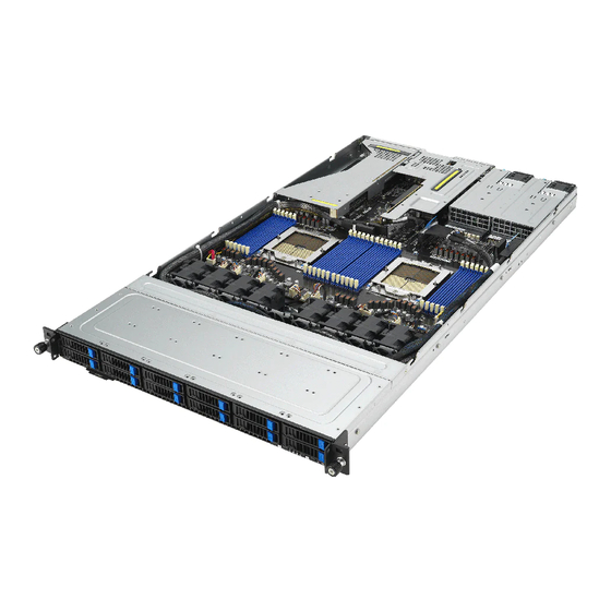
- Page 1 RS700A-E12 Series RS700A-E12-RS12U 1U Rackmount Server User Guide...
- Page 2 ASUSTeK COMPUTER INC. (“ASUS”). ASUS provides this manual “as is” without warranty of any kind, either express or implied, including but not limited to the implied warranties or conditions of merchantability or fitness for a particular purpose. In no...
-
Page 3: Table Of Contents
Contents Safety information ..................... vii About this guide ......................ix Chapter 1: Product Introduction System package contents ................. 1-2 Serial number label ..................1-3 System specifications ................1-4 Front panel features ................... 1-7 Rear panel features ..................1-8 Internal features ..................1-9 LED information .................. - Page 4 Contents Storage devices..................2-18 Expansion slots ..................2-20 2.7.1 Installing an expansion card to the PCIe riser card bracket ..2-21 2.7.2 Installing an OCP 3.0 card ............2-24 2.7.3 Installing an expansion card to the butterfly riser card bracket . 2-25 2.7.4 Installing an ethernet expansion card to the butterfly riser card bracket..........
- Page 5 Contents Chapter 5: BIOS Setup Managing and updating your BIOS ............5-2 5.1.1 ASUS CrashFree BIOS 3 utility........... 5-2 5.1.2 ASUS EZ Flash Utility ..............5-3 5.1.3 BUPDATER utility ............... 5-4 BIOS setup program .................. 5-6 5.2.1 BIOS menu screen ..............5-7 5.2.2...
- Page 6 Contents Event Logs menu ..................5-43 5.9.1 Change Smbios Event Log Settings ......... 5-44 5.9.2 View Smbios Event Log ............5-45 5.10 Server Mgmt menu ................... 5-46 5.10.1 System Event Log ..............5-47 5.10.2 BMC network configuration ............5-48 5.10.3 View System Event Log ............
-
Page 7: Safety Information
Safety information Electrical Safety • Before installing or removing signal cables, ensure that the power cables for the system unit and all attached devices are unplugged. • To prevent electrical shock hazard, disconnect the power cable from the electrical outlet before relocating the system. - Page 8 Lithium-Ion Battery Warning CAUTION! Danger of explosion if battery is incorrectly replaced. Replace only with the same or equivalent type recommended by the manufacturer. Dispose of used batteries according to the manufacturer’s instructions. Heavy System CAUTION! This server system is heavy. Ask for assistance when moving or carrying the system.
-
Page 9: About This Guide
About this guide Audience This user guide is intended for system integrators, and experienced users with at least basic knowledge of configuring a server. Contents This guide contains the following parts: Chapter 1: Product Introduction This chapter describes the general features of the server, including sections on front panel and rear panel specifications. - Page 10 Refer to the following sources for additional information and for product and software updates. ASUS Control Center (ACC) user guide This manual tells how to set up and use the proprietary ASUS server management utility. Visit asuscontrolcenter.asus.com for more information.
-
Page 11: Chapter 1: Product Introduction
Chapter 1: Product Introduction Product Introduction This chapter describes the general features of the server. It includes sections on front panel and rear panel specifications. -
Page 12: System Package Contents
System package contents Check your system package for the following items. RS700A-E12-RS12U Chassis ASUS 1U Rackmount Chassis Motherboard ASUS K14PP-D24 Server Board 1 x 80PLUS Power Supply 1 x 2.5-inch Storage Device Backplane 12 x 2.5-inch Storage Device Trays or Dummy Trays... -
Page 13: Serial Number Label
The product’s serial number contains 12 characters, such as xxSxxxxxxxxx, and printed on the sticker adhered to the server's front cover. The correct serial number of the product is required if you need to request for support from the ASUS Technical Support team. RS700A-E12-RS12U xxSxxxxxxxxx... -
Page 14: System Specifications
System specifications The ASUS RS700A-E12 Series features the ASUS K14PP-D24 server board. The server supports AMD EPYC™ 9004 series processors. Model Name RS700A-E12-RS12U Motherboard K14PP-D24 2 x Socket SP5 (LGA 6096) Processor Support AMD EPYC™ 9004 series (up to 400W) - Page 15 Supports 8 x NVMe: via 4 x MCIO cables* NVMe upgrade Supports 12 x NVMe: via 6 x MCIO cables* option * Please refer to Asus server Upgrade Part List for the latest update 4 x 1Gbe (Intel I350-AM4) RJ45 ports or ®...
- Page 16 Model Name RS700A-E12-RS12U Regulatory Compliance BSMI, CE, CB, FCC (Class A) 842.5 mm x 449 mm x 43.85 mm (1U) Dimension 33.17” x 17.68” x 1.73” Net Weight Kg 14.94 kg (CPU, DRAM & HDD not included) Gross Weight Kg 22.56 kg (CPU, DRAM &...
-
Page 17: Front Panel Features
All bays support 2.5” drives with trays. For extra security, a front bezel (purchased separately) can be installed to prevent unauthorized physical access to the hard drives and power button. Front bezel Bezel keylock Bezel release latch ASUS RS700A-E12 Series... -
Page 18: Rear Panel Features
Management LAN port 1* Expansion slot Expansion slot USB 3.2 Gen 1 ports Expansion slot Optional External Optional LAN port Fan location expansion slots Power button (for GPU) Q-Code LED *This port is for ASUS ASMB11-iKVM only. Chapter 1: Product Introduction... -
Page 19: Internal Features
A protection film is pre-attached to the front cover before shipping. Please remove the protection film before turning on the system for proper heat dissipation. WARNING! HAZARDOUS MOVING PARTS KEEP FINGERS AND OTHER BODY PARTS AWAY ASUS RS700A-E12 Series... -
Page 20: Led Information
LED information 1.7.1 Front panel LEDs Power button Reset button Power LED Message LED Location button LAN1 and LAN3 LED Location LED LAN2 and LAN4 LED Display status Description Power LED System power ON System is normal; no incoming event Message LED A hardware monitor event is indicated Normal status... -
Page 21: Storage Device Status Led
Storage device has failed and should be swapped immediately (For RAID card) GREEN/ Blinking RAID rebuilding (For RAID card) GREEN/ Blinking Locate (For RAID card) GREEN/ Storage device not found GREEN Blinking Read/write data from/into the SATA/SAS storage device ASUS RS700A-E12 Series 1-11... -
Page 22: Lan (Rj45) Leds
1.7.3 LAN (RJ45) LEDs Intel I350-AM4 1GbE LAN port LEDs ® ACT/LINK LED SPEED LED ACT / LINK LED SPEED LED Status Description Status Description No link 10Mbps connection GREEN Linked ORANGE 100 Mbps connection BLINKING Data activity GREEN 1 Gbps connection Intel X710-AT2 10GbE LAN port LEDs ®... -
Page 23: Q-Code Table
SYSHUB mapping memory target type is not supported 0x38 error Attempt to unmap permanently mapped TLB to PSP secure region 0x39 error Unable to map an SMN address to AXI space 0x3A error Unable to map a SYSHUB address to AXI space ASUS RS700A-E12 Series 1-13... - Page 24 ACTION PHASE POST CODE TYPE DESCRIPTION 0x3B error The count of CCXs or cores provided by bootrom is not consistent 0x3C error Uncompressed image size doesn't match value in compressed header 0x3D error Compressed option used in case where not supported 0x3E error Fuse info on all dies don't match...
- Page 25 Inline AES key wrapper stored in DRAM 0xB7 error Completed FW Validation step 0xB8 error Completed FW Validation step 0xB9 error BIOS copy from SPI to DRAM complete 0xBA error Completed FW Validation step (continued on the next page) ASUS RS700A-E12 Series 1-15...
- Page 26 1-16 Chapter 1: Product Introduction...
-
Page 27: Chapter 2: Hardware Information
Chapter 2: Hardware Information Hardware Information This chapter lists the hardware setup procedures that you have to perform when installing or removing system components. -
Page 28: Chassis Cover
Chassis cover 2.1.1 Removing the rear cover Remove the two (2) screws (one on each side of the cover) with a Phillips screwdriver. Loosen the thumbscrew on the rear panel to release the cover from the chassis. Firmly hold the cover and slide it towards the rear panel about half an inch until it is disengaged from the chassis. -
Page 29: Removing The Backplane Cover
2.1.2 Removing the backplane cover Remove the two (2) screws (one on each side of the cover) with a Phillips screwdriver. Hold both ends of the cover (A) and lift from the chassis (B). ASUS RS700A-E12 Series... -
Page 30: Air Duct(S)
Air duct(s) 2.2.1 Removing the air duct(s) Gently lift the two air ducts vertically out of the chassis. Chapter 2: Hardware Information... -
Page 31: Installing The Air Duct(S)
2.2.2 Installing the air duct(s) Align the two air ducts along the edges of the DIMM slots, and then place the air ducts in the chassis ASUS RS700A-E12 Series... -
Page 32: Central Processing Unit (Cpu)
Contact your retailer immediately if the PnP caps are missing, or if you see any damage to the PnP caps/socket contacts/motherboard components. ASUS will shoulder the cost of repair only if the damage is shipment/ transit-related. -
Page 33: Installing The Cpu
2.3.1 Installing the CPU Remove the rear chassis cover. For more information, see the Chassis cover section. Remove the air ducts. For more information, see the Air duct(s) section. Locate the CPU sockets on the motherboard. ASUS RS700A-E12 Series... - Page 34 Loosen the screw on the socket to open the load plate. The load plate screws are T20 models. Lift open the rail frame. Load plate External cap Rail frame Slide the external cap out of the rail frame. External cap Rail frame PnP cap Chapter 2: Hardware Information...
- Page 35 Close the load plate just enough to let it sit on top of the CPU, then secure the load plate using the screw on the socket. The load plate screws are T20 models. A torque value of 13.5±1.0 kgf-cm (11.7±0.9 lbf-in) is recommended. ASUS RS700A-E12 Series...
-
Page 36: Installing The Heatsink
2.3.2 Installing the heatsink Install the CPU. For more information, see the Installing the CPU section. Place the heatsink on the CPU socket and make sure the heatsink screws are aligned with the CPU socket, and the screw holes on the evac is aligned with the screw holes on the chassis Partially tighten each of the six screws with a screwdriver in the order shown both in the illustration and on the heatsink just enough to attach the heatsink to the motherboard. - Page 37 Tighten the remaining heatsink screws to secure the heatsink to the motherboard. A torque value of 5.8±0.3 kgf-cm (5.0±0.3 lbf-in) is recommended. ASUS RS700A-E12 Series 2-11...
-
Page 38: System Memory
System memory 2.4.1 Overview The motherboard comes with 24 Double Data Rate 5 (DDR5) Dual Inline Memory Modules (DIMM) sockets. The figure illustrates the location of the DDR5 DIMM sockets: Chapter 2: Hardware Information 2-12... -
Page 39: Memory Configurations
DIMMS, you can use the recommended memory configuration in this section for reference. • Refer to ASUS Server AVL for the updated list of compatible DIMMs. • Always install DIMMs with the same CAS latency. For optimum compatibility, it is recommended that you obtain memory modules from the same vendor. - Page 40 Recommended memory configuration for 2 CPU Configuration Dual CPU configuration DIMMs CPU1 • • • • • • • • • • • • • • • • • • • • • • • • • • • • •...
-
Page 41: Installing A Dimm
DIMM. Remove the DIMM from the socket. Support the DIMM lightly with your fingers when pressing the retaining clips. The DIMM might get damaged when it flips out with extra force. ASUS RS700A-E12 Series 2-15... -
Page 42: Optional) Front Bezel
(optional) Front bezel For extra security, a front bezel (purchased separately) can be installed to prevent unauthorized physical access to the hard drives and power button. 2.5.1 Removing the front bezel Push the bezel release latch on the front bezel towards the right to unlock the bezel (A) and pull the left side of the bezel slightly away from the system (B). -
Page 43: Installing The Front Bezel
(B). Make sure the bezel release latch is in the unlock state (pushed to the right) before attaching the bezel to the front panel. ASUS RS700A-E12 Series 2-17... -
Page 44: Storage Devices
Storage devices The system supports twelve (12) 2.5” hot-swap SATA/SAS/NVMe storage devices (up to 8 x NVMe/SAS/SATA + 4 x NVMe/SATA). Storage devices installed on the storage device tray connect to the motherboard SATA/SAS/NVMe ports via the SATA/SAS/NVMe backplane. Bay 1 Bay 3 Bay 5 Bay 7... - Page 45 When installed, the SATA/SAS/NVMe connector on the storage device connects to the SATA/SAS/NVMe interface on the backplane. • The storage device tray is correctly placed when its front edge aligns with the bay edge. Repeat steps 1 to 5 to install the other SATA/SAS/NVMe storage devices. ASUS RS700A-E12 Series 2-19...
-
Page 46: Expansion Slots
Expansion slots The barebone server comes with two PCIe slots (A) and (B). These slots are pre-installed with a riser card bracket and a butterfly riser card bracket for installing PCIe expansion cards. You need to remove these expansion card brackets if you want to install PCIe expansion cards. -
Page 47: Installing An Expansion Card To The Pcie Riser Card Bracket
Installing an expansion card to the butterfly riser card bracket. Lift the PCIe riser card bracket out of the chassis by firmly holding the tab (A) and pulling it upwards (B) to detach it from PCIe slot A on the motherboard. ASUS RS700A-E12 Series 2-21... - Page 48 Prepare your expansion cards and flip the PCIe riser card bracket over. Flip the metal bracket lock open (A), and then slide the two metal brackets out of the PCIe riser card bracket (B). (optional) Install the GPU back bracket to the location shown in the illustration below using two (2) screws.
- Page 49 Make sure that no cables are below or in the way of the PCIe riser card bracket when installing it to the chassis. Replace the butterfly riser card bracket. For more information please refer to Installing an expansion card to the butterfly riser card bracket. ASUS RS700A-E12 Series 2-23...
-
Page 50: Installing An Ocp 3.0 Card
2.7.2 Installing an OCP 3.0 card To install an OCP card to the PCIe riser card bracket: (optional) Remove two (2) screws from the bottom of the chassis securing the OCP metal bracket (A) in the rear of the system, then remove the OCP metal bracket (B). Insert the OCP 3.0 card into the OCP 3.0 slot from the rear of the system. -
Page 51: Installing An Expansion Card To The Butterfly Riser Card Bracket
Lift the butterfly riser out of the chassis by firmly holding it by the tab and pulling it upwards to detach it from the PCIE x16 slot on the motherboard. Flip the butterfly riser card bracket over, and then flip the metal bracket lock open (A) to remove the metal bracket (B). ASUS RS700A-E12 Series 2-25... - Page 52 Install the expansion card to the RS2_PCIE1 slot on the butterfly riser card bracket (A), and then flip the metal bracket lock back to secure the card (B). Align the butterfly riser card bracket to PCIe slot B on the motherboard and push down until the butterfly riser card bracket is seated securely in the chassis.
-
Page 53: Installing An Ethernet Expansion Card To The Butterfly Riser Card Bracket
RS2_LAN_PCIE1 slot (A) on the butterfly riser card bracket, then secure it using two (2) screws (B). Follow step 4-5 of Installing an expansion card to the butterfly riser card bracket to install the butterfly riser card bracket to the chassis. ASUS RS700A-E12 Series 2-27... -
Page 54: Installing An Hba/Raid Card To The Butterfly Riser Card Bracket
2.7.5 Installing an HBA/RAID card to the butterfly riser card bracket Prepare the HBA/RAID card. Remove the two (2) screws on the HBA/RAID card (A), and then remove the card bracket (B). Card bracket Follow step 1 of Installing an expansion card to the butterfly riser card bracket. to remove the butterfly riser card bracket from the chassis. - Page 55 Connect the MCIO/miniSAS cables from the HBA/RAID card (A) to the PE2_MCIO_IN1 connector or NVMe/SATA/SAS backplane (B). Refer to the section Backplane cabling for the locations of the MCIO connectors. • The illustration above is for reference only. • For more information or assistance, refer to www.asus.com. ASUS RS700A-E12 Series 2-29...
-
Page 56: Removing The Hba/Raid Card From The Butterfly Riser Card Bracket
2.7.6 Removing the HBA/RAID card from the butterfly riser card bracket Follow step 1 of Installing an expansion card to the butterfly riser card bracket to remove the butterfly riser card bracket from the chassis. Disconnect the cables from the HBA/RAID card. Remove the two (2) screws securing the card to the butterfly riser card bracket (A), and then remove the HBA/RAID card (B). -
Page 57: Installing The Cache Vault Power Module
Connect the Cache Vault Power Module to the S-CAP connector on the HBA RAID card. Install the butterfly riser card bracket back into the PCIe slot on the motherboard. Make sure that the gold fingers on the butterfly riser card bracket is firmly seated in place. ASUS RS700A-E12 Series 2-31... -
Page 58: Installing An M.2 (Ngff) Card
2.7.8 Installing an M.2 (NGFF) card You may install M.2 cards (supports 2260, 2280) to the onboard M.2 (NGFF) slots on the motherboard. Remove the riser card bracket. Please refer to Installing an expansion card to the butterfly riser card bracket for more information. Locate the M.2 connectors (NGFF1 / NGFF2) on the motherboard. -
Page 59: Configuring An Expansion Card
ACPI Mode when used IRQ Holder for PCI Steering IRQ Holder for PCI Steering PS/2 Compatible Mouse Port Numeric Data Processor Primary IDE Channel Secondary IDE Channel * These IRQs are usually available for ISA or PCI devices. ASUS RS700A-E12 Series 2-33... -
Page 60: Cable Connections
Cable connections • The bundled system cables are pre-connected before shipment. You do not need to disconnect these cables unless you are going to remove pre-installed components to install additional devices. • Refer to Chapter 4 for detailed information on the connectors. Pre-connected system cables Panel connector (connected to front I/O board) 8-pin BPPWR1-4 power connectors (connected to backplane) -
Page 61: Backplane Cabling
Bay 5 and 6 support on Bay 1 and 2 NVME1 NVME3 NVME5 NVME7 NVME9 NVME11 BP12LE32G-25-R1PB NVME2 NVME6 NVME8 NVME10 NVME12 NVME4 Connects to NVMe/SAS/SATA storage devices (SAS support requires an optional HBA/RAID card) ASUS RS700A-E12 Series 2-35... -
Page 62: Storage Device Configuration And Cabling
2.10 Storage device configuration and cabling This section illustrates some storage configurations that are recommended for your server system. Before you start installing or removing the storage device cables, ensure that you have installed the correct storage devices into the supported bays. Refer to Storage Devices for details on how to install storage devices. -
Page 63: 12 X Sata Storage Device Configuration And Cabling
Refer to Storage Devices for details on how to install storage devices. SATA SATA SATA SATA SATA SATA SATA SATA SATA SATA SATA SATA Remove the rear and backplane covers. For more information, refer to Removing the rear cover and Removing the backplane cover. ASUS RS700A-E12 Series 2-37... - Page 64 Locate the backplane (A), and then cut the cable tie(s) (B). Backplane Chapter 2: Hardware Information 2-38...
- Page 65 SlimSAS P1 cable from SLIMPCIE_SATA1 connector SLIMPCIE_SATA1 connector the SLIMPCIE_SATA1 on the motherboard on the motherboard connector on the motherboard Tie the cables with cable tie(s) (A), then reinstall the backplane cover to the chassis (B). Backplane ASUS RS700A-E12 Series 2-39...
-
Page 66: Nvme Storage Device Configuration And Cabling
2.10.2 4 x NVMe storage device configuration and cabling • The illustrations in this section are for reference only and may vary between models. • You may still support either SATA for bays 1 to 12 or SAS for bays 1 to 8 with this configuration, for more information please refer to the following sections: - SATA support for bays 1 to 12: 12 x SATA storage device configuration and cabling... - Page 67 Locate the backplane (A), and then cut the cable tie(s) (B). Backplane ASUS RS700A-E12 Series 2-41...
- Page 68 Connect the slimline PCIe cables to the motherboard and the backplane. MCIO_P2: Connect MCIO_P1: Connect SlimSAS cable from SlimSAS cable from the MCIOPCIE1 the MCIOPCIE1 connector on the connector on the motherboard motherboard Tie the cables with cable tie(s) (A), then reinstall the backplane cover to the chassis (B). Backplane Chapter 2: Hardware Information 2-42...
-
Page 69: 8 X Nvme Storage Device Configuration And Cabling
Refer to section Storage Devices for details on how to install storage devices. NVMe NVMe NVMe NVMe NVMe NVMe NVMe NVMe Remove the rear and backplane covers. For more information, refer to Removing the rear cover and Removing the backplane cover. ASUS RS700A-E12 Series 2-43... - Page 70 Locate the backplane (A), and then cut the cable tie(s) (B). Backplane Chapter 2: Hardware Information 2-44...
- Page 71 PCIe cable slimline PCIe cable from the MCIOPCIE3 from the MCIOPCIE1 connector on the connector on the motherboard motherboard Tie the cables with cable tie(s) (A), then reinstall the backplane cover to the chassis (B). Backplane ASUS RS700A-E12 Series 2-45...
-
Page 72: 12 X Nvme Storage Device Configuration And Cabling
2.10.4 12 x NVMe storage device configuration and cabling • The illustrations in this section are for reference only and may vary between models. • You may still support one of the following configurations with this configuration, for more information please refer to the following sections: - SATA support for bays 1 to 12: 12 x SATA storage device configuration and cabling - SAS support for bays 1 to 8 and SATA support for bays 9 to 12: 8 x SAS and 4 x... - Page 73 Locate the backplane (A), and then cut the cable tie(s) (B). Backplane ASUS RS700A-E12 Series 2-47...
- Page 74 Connect the slimline PCIe cables to the motherboard and the backplane. MCIO_P4: Connect slimline MCIO_P6: Connect slimline MCIO_P2: Connect slimline PCIe cable from the PCIe cable from the PCIe cable from the MCIOPCIE4 connector on GENZPCIE6 connector on MCIOPCIE2 connector on the the motherboard the motherboard motherboard...
-
Page 75: Sas And 4 X Sata Storage Device Configuration And Cabling
Install the storage devices into the supported bays. Refer to section Storage Devices for details on how to install storage devices. SATA SATA SATA SATA Install the HBA/RAID card to your system. For more information, refer to Installing an HBA/RAID card. ASUS RS700A-E12 Series 2-49... - Page 76 Locate the backplane (A), and then cut the cable tie(s) (B). Backplane Chapter 2: Hardware Information 2-50...
- Page 77 SlimSAS cable from the SlimSAS cable from the SlimSAS cable from the SlimSAS connector on the HBA/RAID card HBA/RAID card motherboard Tie the cables with cable tie(s) (A), then reinstall the backplane cover to the chassis (B). Backplane ASUS RS700A-E12 Series 2-51...
-
Page 78: Removable/Optional Components
2.11 Removable/optional components This section explains how to install optional components into the system and covers the following components: System fans Redundant power supply module Ensure that the system is turned off before removing any components. You may need to remove previously installed component or factory shipped components when installing optional components. - Page 79 Insert the fan into the fan cage. The airflow directional arrow on the fan should point towards the system rear panel. Ensure the notches on the fan module sit firmly into the notch holes in the chassis. Connect the system fan cable to the fan connector on the motherboard. ASUS RS700A-E12 Series 2-53...
- Page 80 To install the external rear fan (on selected models): • We recommend installing the external fan when you have GPU cards installed. • The external fan is only available with selected models. Use a screwdriver to pry open the slot. Do not install the 4-port ethernet expansion card if you wish to install the external rear fan.
- Page 81 Connect the cables on the rear external fan to the REAR_FAN1 and REAR_FAN2 connectors on the motherboard. Align and place the rear external fan on the chassis. Secure the rear external fan to the chassis with the thumbscrews. ASUS RS700A-E12 Series 2-55...
-
Page 82: Redundant Power Supply Module
2.11.2 Redundant power supply module To replace a failed redundant power supply module: Lift up the power supply module lever. Module lever Hold the power supply module lever and press the PSU latch, then pull the power supply module out of the system chassis. -
Page 83: Chapter 3: Installation Options
Chapter 3: Installation Options Installation Options This chapter describes how to install the optional components and devices into the barebone server. -
Page 84: Tool-Less Friction Rail Kit
Tool-less Friction Rail Kit The tool-less design of the rail kit allows you to easily install the rack rails into the server rack without the need for additional tools. The kit also comes with a metal stopping bracket that can be installed to provide additional support and stability to the server. The tool-less rail kit package includes the following: Fixing latches Set of screws... - Page 85 Press the spring lock on the other end of rail then insert the stud into the mounting hole on the rack post. Extend the rack rail, if necessary. Perform steps 3 to 4 for the other rack rail. Ensure that the installed rack rails (left and right) are aligned, secured, and stable in place. ASUS RS700A-E12 Series...
-
Page 86: Rail Kit Dimensions
Lift the server chassis and insert it into the rack rail. • Ensure that the rack rail cabinet and the rack posts are stable and standing firmly on a level surface. • We strongly recommend that at least two able-bodied persons perform the steps described in this guide. -
Page 87: Ball Bearing Rail Kit
2 x M5X13.5L extended nuts • The bundled screw package includes different types of screws for you to choose from, not all screws are required for the installation. • Package content and specifications are subject to change without notice. ASUS RS700A-E12 Series... - Page 88 3.2.1 Attaching the rack rails • Ensure that the rack rail cabinet and the rack posts are stable and standing firmly on a level surface. • We strongly recommend that at least two able-bodied persons perform the steps described in this guide. •...
- Page 89 The blue release tab is available on 1200 mm rack rails. This blue release tab is used to further extend or retract the inner rail. Repeat steps 2 to 5 for the other rack rail. Ensure that the installed rack rails (left and right) are aligned, secured, and stable in place. ASUS RS700A-E12 Series...
- Page 90 Remove the three (3) screws from both left and right sides of the server system chassis, then remove the metal plate. The illustration below only shows one side of the server system chassis, but the screws on the other side should be at the same place. Metal plate Align the inner rails with the studs on both sides of the server system, install the inner rails to the server system, then slide the inner rails toward the rear of the server system...
- Page 91 Inner rail Intermediate rail Blue release tab White release tab The blue release tab is available on 1200 mm rack rails. This blue release tab is used to further extend or retract the inner rail. ASUS RS700A-E12 Series...
- Page 92 RS700A-E12-RS12U Front View Chapter 3: Installation Options 3-10...
-
Page 93: Cable Management Arm (Optional For 1200 Mm Rack Rails)
Refer to section Rail Kit for the steps on installing the rack rails into the rack. Press the round button on the pivot receptor, then rotate the pivot receptor to the left or right for a left pivot configuration or right pivot configuration. Left pivot configuration Right pivot configuration ASUS RS700A-E12 Series 3-11... - Page 94 Align the three receptors on the CMA with the connectors on the rack rails. Intermediate rail connector Pivot receptor Inner rail connector (hidden) Inner receptor Intermediate rail connector Outer receptor The installation steps in this section uses a Left pivot configuration as an example, the installation steps for a Right pivot configuration is similar.
- Page 95 Align and connect the pivot receptor on the CMA with the connector on the other intermediate rail. Pass the cables from the server system through the hook and loop fasteners and the cable fasteners on the CMA to complete. Hook and loop fasteners Cable fasteners ASUS RS700A-E12 Series 3-13...
- Page 96 Chapter 3: Installation Options 3-14...