Table of Contents
Advertisement
Quick Links
—
ABB DRIVES FOR WATER
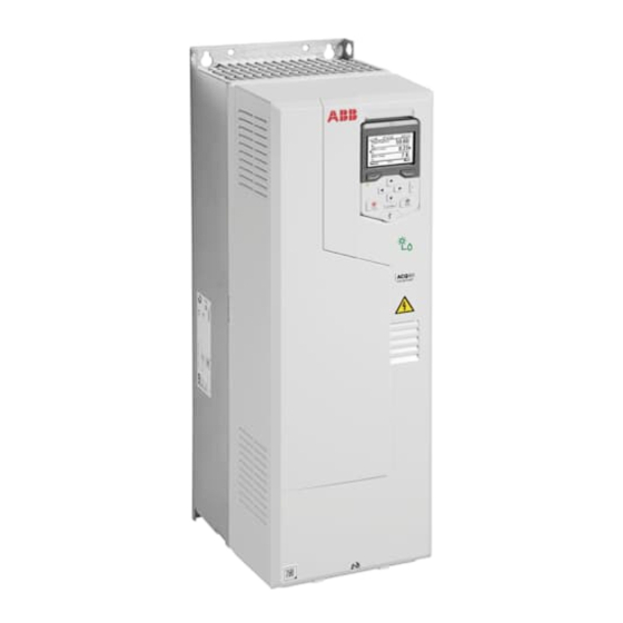
ACQ80-01 (30 to 55 kW) drives
Quick installation and start-up guide
This guide is applicable to ACQ80-01 drives, frames R4 and R5.
Documentation in other languages
Safety instructions
WARNING! Obey these instructions. If you ignore them, injury or death, or damage to the equipment can occur. If
you are not a qualified electrical professional, do not do electrical installation or maintenance work.
•
Do not do work on the drive, motor cable, motor, or control cables when the drive is connected to the input power.
Before you start the work, isolate the drive from all dangerous voltage sources and make sure that it is safe to start the
work. Always wait for 5 minutes after disconnecting the input power to let the intermediate circuit capacitors
discharge.
•
Do not do work on the drive when a rotating permanent magnet motor is connected to it. A rotating permanent
magnet motor energizes the drive, including its input and output terminals.
•
Frames R5: Do not tilt the drive. The drive is
heavy and has a high center of gravity. It can
topple accidentally.
•
Frames R5: Lift the drive with a lifting device.
Use the lifting eyes of the drive.
1. Unpack the delivery
Keep the drive in its package until you are ready
to install it. After unpacking, protect the drive
from dust, debris and moisture. Make sure that
these items are included:
•
cable box (frame R5, IP21 [UL Type 1])
•
drive
•
mounting template
•
control panel
•
quick installation and start-up guide
•
multilingual residual voltage warning stickers
•
hardware and firmware manuals, if ordered
•
options in separate packages, if ordered.
Make sure that there are no signs of damage to the items.
2. Reform the capacitors
If the drive has not been powered up for a year or more, you must reform the DC link capacitors. Refer to
reforming instructions
(3BFE64059629
3. Select the cables and fuses
•
Select the power cables. Obey the local regulations.
•
Input power cable: ABB recommends to use symmetrical shielded cable (VFD cable) for the best EMC performance.
•
Motor cable: Use symmetrical shielded cable (VFD cable) for the best EMC performance. Symmetrical shielded cable
also reduces bearing currents, wear, and stress on motor insulation.
•
Power cable types: In IEC installations, use copper or aluminum cables (if permitted). In UL installations, use only
copper cables.
•
Current rating: max. load current.
•
Voltage rating: min. 380 V AC.
•
Temperature rating: In IEC installations, select a cable rated for at least 70 °C (158 °F) maximum permissible
temperature of conductor in continuous use. In UL installations and for drives with option +B056 (IP55, UL Type 12),
select a cable rated for at least 75 °C (167 °F).
•
Ratings, fuses and typical power cable sizes
Size: Refer to
power cables
for the maximum cable sizes.
•
Select the control cables. Use double-shielded twisted-pair cable for analog signals. Use double-shielded or single-
shielded cable for the digital, relay and I/O signals. Do not run 24 V and 115/230 V signals in the same cable.
•
Protect the drive and input power cable with the correct fuses. Refer to
Ecodesign information (EU 2019/1781)
R5
[English]).
for the typical cable sizes and to
About this document
3AXD50001017217 Rev A EN
2023-03-27
© 2023 ABB. All rights reserved.
Original instructions.
R5
Terminal data for the
Ratings, fuses and typical power cable sizes
1
Capacitor
.
Advertisement
Table of Contents

Related Manuals for ABB ACQ80-01


Summary of Contents for ABB ACQ80-01
- Page 1 Select the power cables. Obey the local regulations. • Input power cable: ABB recommends to use symmetrical shielded cable (VFD cable) for the best EMC performance. • Motor cable: Use symmetrical shielded cable (VFD cable) for the best EMC performance. Symmetrical shielded cable also reduces bearing currents, wear, and stress on motor insulation.
- Page 2 × 2 × 2 × 4 4. Examine the installation site Examine the site where you will install the drive. Make sure that: • The installation site is sufficiently ventilated or cooled to remove heat from the drive. • Ambient conditions The ambient conditions meet the requirements.
- Page 3 Frames R4: Put the drive on the wall and tighten the screws Frame R5, IP21 (UL Type 1): Install the cable box 3×M5 Frames R5: Put the drive on the wall and tighten the screws...
-
Page 4: Remove The Cover(S)
1) A residual current device must be installed in the supply system. 2) ABB does not guarantee the EMC category or the operation of the ground leakage detector built inside the drive. 9. Measure the insulation of the power cables and the motor Measure the insulation of the input cable before you connect it to the drive. -
Page 5: Connection Procedure
Ground connection should be common for MOV, drive, and pump. Note: ACQ80-01 drive is intended to be used for speed control of 3-phase AC pump motors and is powered from either AC Grid or DC photo-voltaic array. ABB recommends not to use it as an island grid forming inverter or to supply generic single phase or 3-phase loads, other than the 3-phase AC pump motors. - Page 6 Terminal data for the power cables Connect the power cables. For the tightening torques, refer to • Connect the phase conductors of the motor cable to terminals T1/U, T2/V and T3/W. Connect the twisted shield of the cable to the grounding terminal. (a) •...
-
Page 7: Connect The Control Cables
Ground also the pair-cable shields and grounding wire at the SCR terminal. Tie all control cables to the provided cable tie mounts. Default I/O connections (ABB standard macro) Reference voltage and analog inputs and outputs Signal cable shield (screen) Ext. - Page 8 Control cable installation examples This section shows examples for routing the control cables in frame R4. Frame R5 is similar to frame R4.
-
Page 9: Start Up The Drive
EIA-485 embedded fieldbus connection You can connect the drive to a serial communication link with a fieldbus adapter module or the embedded fieldbus interface. The embedded fieldbus interface supports the Modbus RTU protocol. To configure Modbus RTU communication with the embedded fieldbus: Connect the fieldbus cable and the required I/O signals. - Page 10 PID, fieldbus, advanced functions and clock, region and display. You can also reset logs, parameters, and the control panel Home view. ABB recommends that you make at least these additional settings: • Choose a macro or set start, stop and reference values separately •...
-
Page 11: Fieldbus Communication
3381 Output phase loss All three phases are not connected to the motor. 5090 STO hardware failure STO hardware diagnostics has detected hardware failure. Contact ABB. A5A0 5091 Safe torque off The Safe torque off (STO) function is active. A7CE... -
Page 12: Ambient Conditions
TT, and IT (ungrounded or high-resistance symmetrically grounded). For the installation requirements for corner-grounded systems at this altitude, contact your local ABB representative. Surrounding air temperature -15 … +50 °C (5 … 122 °F). No frost permitted. The rated output current must be derated by 1% for each 1 °C (1.8 °F) above 40 °C (104 °F). -
Page 13: Technical Data
WEEE TÜV Nord Solar impulse Related documents Document Code (English) ACQ80-01 (30 kW to 55 kW) Drive HW manual 3AXD50001017101 ACQ80 standard control program firmware manual 3AXD50000170654 ACx-AP-x assistant control panels user’s manual 3AUA0000085685 Drive Composer PC tool user's manual...