
Related Manuals for Motorola M68EM05C0


Summary of Contents for Motorola M68EM05C0
- Page 1 Freescale Semiconductor, Inc. M68EM05C0UM/D M68EM05C0 E M U L A T I O N M O D U L E U S E R ’ S M A N U A L For More Information On This Product, Go to: www.freescale.com...
- Page 2 Freescale Semiconductor, Inc. For More Information On This Product, Go to: www.freescale.com...
- Page 3 Freescale Semiconductor, Inc. M68EM05C0 Emulation Module User’s Manual © Motorola, Inc., 1996; All Rights Reserved For More Information On This Product, Go to: www.freescale.com...
- Page 4 Motorola product could create a situation where personal injury or death may occur. Should Buyer purchase or use...
-
Page 5: Table Of Contents
Contents ..........27 M68EM05C0 Schematics ........27... - Page 6 Freescale Semiconductor, Inc. M68EM05C0UM/D MOTOROLA For More Information On This Product, Go to: www.freescale.com...
-
Page 7: General Description
Logic Analyzer Connector Pin Assignments ....15 Introduction Your M68EM05C0 gives your Motorola development tool the ability to emulate target systems based on the MC68HC05C0 MCUs. By substituting a different emulation module (EM), you can enable your Motorola development tool to emulate other MCUs. -
Page 8: Emulation Components
Motorola’s complete emulation system consists of the emulation module described in this manual as well as other separately purchased options described in the following paragraphs. The following items are included with the M68EM05C0 emulation module: • An M68EM05C0 emulation module (EM) — the printed circuit board that enables system functionality for 05C0 MCUs. -
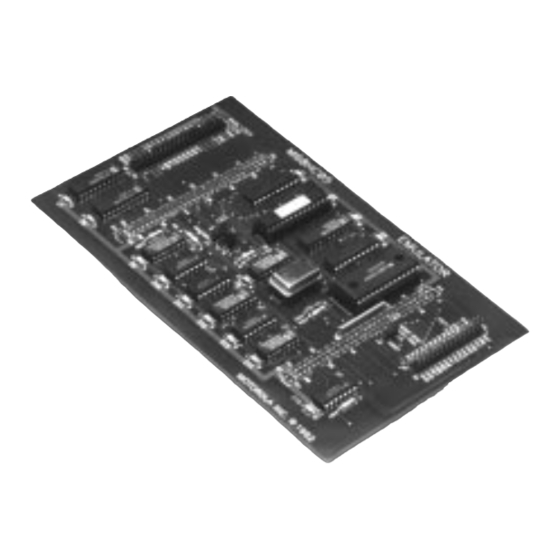
Page 9: Emulation Module Layout
Target connectors J2 and J3 are the interface to a target system; these connectors use a separately purchased target cable assembly. When you install the M68EM05C0 on the MMDS05, the target cable passes through the slit in the station module enclosure. Connector J1 connects to a logic analyzer. -
Page 10: Target Cable Assemblies
General Description Target Cable Assemblies Target Cable Assemblies To connect your M68EM05C0 to a target system, you need a separately purchased target cable assembly. The target cable connects to the emulator via connectors J2 and J3 on the M68EM05C0 emulation module. Pin assignments and signal... - Page 11 TARGET HEAD ADAPTER M68TC05C0FN44 40-PIN DIP FLEX CABLE: M68CBL05B TARGET HEAD ADAPTER M68TB05C0P40 42-PIN SDIP FLEX CABLE: M68CBL05B TARGET HEAD ADAPTER M68TB05C0B42 Figure 2. Target Cable Assembly M68EM05C0UM/D MOTOROLA General Description For More Information On This Product, Go to: www.freescale.com...
-
Page 12: Connector Information
Connector Information Connector Information The reachable connectors on the M68EM05C0 module provide access to the user mode emulation signals (J2 and J3) as well as select internal signals (J1). Connectors J2 and J3 are used for a cable interface to a user’s target system, while connector J1 is used to connect a logic... - Page 13 Becomes the timer compare (TCMP) output pin when the output compare mode feature of the 16-bit timer subsystem is enabled M68EM05C0UM/D MOTOROLA General Description For More Information On This Product, Go to: www.freescale.com...
- Page 14 MMDS05 status window OSCILLATOR 1 — A possible clock source input for the M68EM05C0 board; system bus frequency is OSC1 OSC1÷ 4; use of this signal is controlled by jumper header W1.
-
Page 15: Logic Analyzer Connector Pin Assignments
— — — LA11 LA12 LA10 LA13 LA14 LA15 LR/W — — — — — ACLK — RESET Figure 4. Connector J1 Pin Assignments M68EM05C0UM/D MOTOROLA General Description For More Information On This Product, Go to: www.freescale.com... - Page 16 ACLK. Also, data is valid on the AD BUS at ACLK’s rising edge. RESET — Active-low signal; will be asserted RESET during internally or externally caused resets M68EM05C0UM/D General Description MOTOROLA For More Information On This Product, Go to: www.freescale.com...
-
Page 17: Contents
Introduction ..........18 Setting M68EM05C0 Jumper Headers ......19 Clock Source Select Header, W1 . -
Page 18: Introduction
Introduction Introduction The following paragraphs explain how to configure and use your M68EM05C0 as part of an MMDS or MMEVS system. For other parts of system installation and configuration, see either the MMDS05 Operations Manual (MMDS05OM/D) or MMEVS05/MMEVS08 Operations Manual (MMEVS0508OM/D). -
Page 19: Setting M68Em05C0 Jumper Headers
MMDS/MMEVS Configuration and Operation Setting M68EM05C0 Jumper Headers Setting M68EM05C0 Jumper Headers Your M68EM05C0 has five jumper headers — W1 through W5. The following explains how to configure these components. Clock Jumper header W1 determines the source of the clock signal. The... -
Page 20: Port D Source Select Header, W2
Header, W2 jumper is determined by the version of MC68HC05C0 silicon used as the resident MCU and installed in the XU11 socket on the M68EM05C0 board. For first pass silicon, the port D I/O logic is rebuilt external to the MCU using a port replacement unit (PRU). -
Page 21: Internal Read Visibility (Irv) Header, W4
Freescale Semiconductor, Inc. MMDS/MMEVS Configuration and Operation Setting M68EM05C0 Jumper Headers Internal Read The internal read visibility jumper enables both the internal read visibility Visibility (IRV) (IRV) and load instruction register visibility (LIRV) bits of the Header, W4 configuration register. That is, to emulate these bits being set or cleared, you should configure this jumper appropriately instead of modifying the associated bits in the configuration register (CNFGR). -
Page 22: External Memory Select Header, W5
Freescale Semiconductor, Inc. MMDS/MMEVS Configuration and Operation Setting M68EM05C0 Jumper External Memory Jumper header W5 determines where the external memory range Select Header, W5 $0240-$FFFF resides. The default position, with the jumper removed, will use the RAM residing on the control board. If the jumper is installed, the user should connect external memory to the emulator through a target cable connected to J2 and J3. -
Page 23: Personality Files Usage
Your MMDS or MMEVS development system uses a specific personality file to emulate an MC68HC05C0 MCU: file 00023Vxx.MEM. This file is on an individual disk shipped with the M68EM05C0. This file name follows the pattern for all personality files, 00ZZZVxx.MEM, where ZZZ is the EM identifier of MCU name and xx is the version of the file. -
Page 24: Mc68Hc05C0 Emulation
The state of the LIR/MODE pin during a power-on reset selects the mode the MCU will run in: muxed or non-muxed. In emulation: The MCU mode is selected by the jumper position of W3 on the M68EM05C0 module. M68EM05C0UM/D MMDS/MMEVS Configuration and Operation MOTOROLA For More Information On This Product, Go to: www.freescale.com... -
Page 25: Irv And Lirv Operation And The Configuration Register
The IRV and LIRV are defaulted to 1 and must remain a logic 1. Writes to the CNFGR register should always leave these bits set. The IRV jumper (W4 on the M68EM05C0) can be used to control the control signals (LIR, RD, WR, and the chip select lines) driven out during an internal access cycle. -
Page 26: Remaining System Installation
• Ensure that the power to the development tool is off. • If installing the M68EM05C0 in an MMDS05 station module, remove the panel from the station module top. • Fit together EM connectors P1 and P2 (on the bottom of the board) and platform board DIN connectors. -
Page 27: Schematics
Contents M68EM05C0 Schematics ........27 Sheet 1 of 5......... . .29 Sheet 2 of 5. - Page 28 Freescale Semiconductor, Inc. Schematics M68EM05C0 Schematics M68EM05C0UM/D Schematics MOTOROLA For More Information On This Product, Go to: www.freescale.com...
- Page 29 Freescale Semiconductor, Inc. Schematics M68EM05C0 Schematics M68EM05C0UM/D MOTOROLA Schematics For More Information On This Product, Go to: www.freescale.com...
- Page 30 Freescale Semiconductor, Inc. Schematics M68EM05C0 Schematics M68EM05C0UM/D Schematics MOTOROLA For More Information On This Product, Go to: www.freescale.com...
- Page 31 Freescale Semiconductor, Inc. Schematics M68EM05C0 Schematics M68EM05C0UM/D MOTOROLA Schematics For More Information On This Product, Go to: www.freescale.com...
- Page 32 Freescale Semiconductor, Inc. Schematics M68EM05C0 Schematics M68EM05C0UM/D Schematics MOTOROLA For More Information On This Product, Go to: www.freescale.com...
- Page 33 Freescale Semiconductor, Inc. Schematics M68EM05C0 Schematics M68EM05C0UM/D MOTOROLA Schematics For More Information On This Product, Go to: www.freescale.com...
- Page 34 Freescale Semiconductor, Inc. Schematics M68EM05C0 Schematics M68EM05C0UM/D Schematics MOTOROLA For More Information On This Product, Go to: www.freescale.com...
- Page 35 Freescale Semiconductor, Inc. Schematics M68EM05C0 Schematics M68EM05C0UM/D MOTOROLA Schematics For More Information On This Product, Go to: www.freescale.com...
- Page 36 Freescale Semiconductor, Inc. Schematics M68EM05C0 Schematics M68EM05C0UM/D Schematics MOTOROLA For More Information On This Product, Go to: www.freescale.com...
- Page 37 Freescale Semiconductor, Inc. Schematics M68EM05C0 Schematics M68EM05C0UM/D MOTOROLA Schematics For More Information On This Product, Go to: www.freescale.com...
- Page 38 Freescale Semiconductor, Inc. Schematics M68EM05C0 Schematics M68EM05C0UM/D Schematics MOTOROLA For More Information On This Product, Go to: www.freescale.com...
- Page 39 Freescale Semiconductor, Inc. For More Information On This Product, Go to: www.freescale.com...
- Page 40 JAPAN: Nippon Motorola Ltd.; Tatsumi-SPD-JLDC, Toshikatsu Otsuki, 6F Seibu-Butsuryu-Center, 3-14-2 Tatsumi Koto-Ku, Tokyo 135, Japan. 03-3521-8315 HONG KONG: Motorola Semiconductors H.K. Ltd.; 8B Tai Ping Industrial Park, 51 Ting Kok Road, Tai Po, N.T., Hong Kong. 852-26629298 For More Information On This Product, M68EM05C0UM/D Go to: www.freescale.com...