Table of Contents
Advertisement
Quick Links
Advertisement
Table of Contents

Related Manuals for Lenovo ThinkSystem ST650 V3


Summary of Contents for Lenovo ThinkSystem ST650 V3
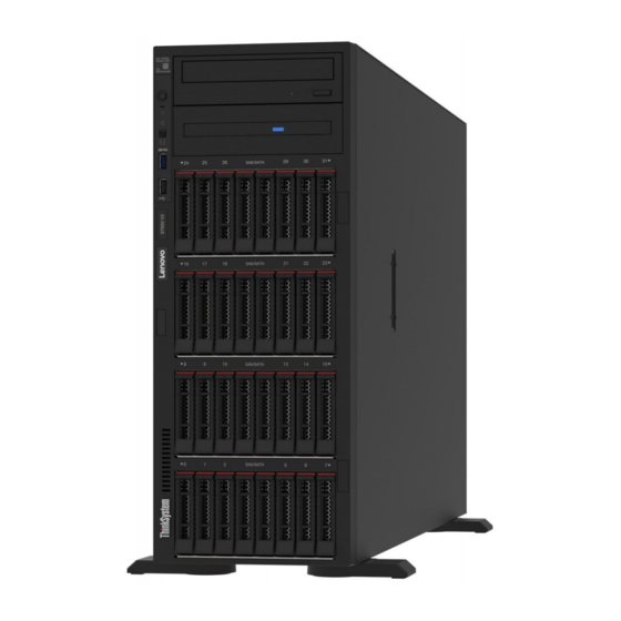
- Page 1 ThinkSystem ST650 V3 System Configuration Guide Machine Types: 7D7A,7D7B...
- Page 2 Before using this information and the product it supports, be sure to read and understand the safety information and the safety instructions, which are available at: https://pubs.lenovo.com/safety_documentation/ In addition, be sure that you are familiar with the terms and conditions of the Lenovo warranty for your server, which can be found at: http://datacentersupport.lenovo.com/warrantylookup First Edition (May 2023) ©...
-
Page 3: Table Of Contents
Contents ....i Identify the server and access the Lenovo XClarity Safety ....iii Controller . - Page 4 ThinkSystem ST650 V3 System Configuration Guide...
-
Page 5: Safety
Vor der Installation dieses Produkts die Sicherheitshinweise lesen. Prima di installare questo prodotto, leggere le Informazioni sulla Sicurezza. Les sikkerhetsinformasjonen (Safety Information) før du installerer dette produktet. Antes de instalar este produto, leia as Informações sobre Segurança. © Copyright Lenovo 2023... -
Page 6: Safety Inspection Checklist
1 & IEC 60950-1, the standard for Safety of Electronic Equipment within the Field of Audio/Video, Information Technology and Communication Technology. Lenovo assumes you are qualified in the servicing of equipment and trained in recognizing hazards energy levels in products. Access to the equipment is by the use of a tool, lock and key, or other means of security, and is controlled by the authority responsible for the location. - Page 7 Click Power ➙ Power Cables to see all line cords. • Make sure that the insulation is not frayed or worn. 3. Check for any obvious non-Lenovo alterations. Use good judgment as to the safety of any non-Lenovo alterations.
- Page 8 ThinkSystem ST650 V3 System Configuration Guide...
-
Page 9: Chapter 1. Introduction
Chapter 1. Introduction The ThinkSystem ST650 V3 server (Types 7D7A and 7D7B) is a 4U tower server designed for performance and expansion for various IT workloads. With the modular design, the server is flexible to be customized for maximum storage capacity or high storage density with selectable input/output options and tiered system management. - Page 10 Demand, see: https://fod.lenovo.com/lkms • Lenovo XClarity Controller (XCC) The server supports Lenovo XClarity Controller 2 (XCC2). For additional information about Lenovo XClarity Controller 2 (XCC2), refer to https://sysmgt.lenovofiles.com/help/topic/lxcc_frontend/lxcc_overview.html With different versions, the Lenovo XClarity Controller is the common management controller for Lenovo ThinkSystem server hardware.
-
Page 11: Tech Tips
Tech Tips Lenovo continually updates the support website with the latest tips and techniques that you can use to solve issues that your server might encounter. These Tech Tips (also called retain tips or service bulletins) provide procedures to work around issues or solve problems related to the operation of your server. -
Page 12: Specifications
“Rear button” on page 7 • “Storage controller” on page 8 • “System fan” on page 9 • “Electrical input” on page 9 • “Minimal configuration for debugging” on page 10 • “Operating systems” on page 10 ThinkSystem ST650 V3 System Configuration Guide... -
Page 13: Technical Specifications
• Scalable up to 32 cores per socket • Supports up to 3 UPI links at 16 GTS • Supports TDP up to 250W For a list of supported processors, see https://serverproven.lenovo.com Memory Memory Important: See “Memory module installation rules and order” in User Guide or Hardware Maintenance Guide for detailed information about memory configuration and setup. - Page 14 Notes: • Slots 2, 4, 6, 8, and 9 in ThinkSystem ST650 V3 are open-end design, which means that these slots can accept adapters with a longer edge connector than the physical length of the slot connector. For example, if a x16 adapter is installed in the x8 slot 2 of the server, half of the edge connector will not be connected to the slot.
- Page 15 • Lenovo XClarity Controller (XCC), which provides service processor control and monitoring functions, video controller, and remote keyboard, video, mouse, and remote drive capabilities. – The server supports Lenovo XClarity Controller 2 (XCC2). For additional information about Lenovo XClarity Controller 2 (XCC2), refer to https://sysmgt.lenovofiles.com/help/topic/lxcc_frontend/lxcc_overview.html...
- Page 16 • See “Install a HL PCIe adapter” in the User Guide or Hardware Maintenance Guide for detailed information about the technical rules of PCIe slots. • For more information about the supported HBA/RAID adapters, see Lenovo ThinkSystem RAID Adapter and HBA Reference. ThinkSystem ST650 V3 System Configuration Guide...
- Page 17 System fan System fan The server supports up to four hot-swap fans: • 9238 single-rotor hot-swap fans • 9256 dual-rotor hot-swap fans Notes: • Single-rotor hot-swap fans cannot be mixed with dual-rotor hot-swap fans. • When the system is powered off but still plugged in to AC power, the fan in slot 4 may continue to spin at a much lower speed.
-
Page 18: Mechanical Specifications
– Without security door: 710.8 mm (27.98 inches) – With security door: 733.8 mm (28.89 inches) Weight • 2.5-inch drive configuration – Maximum: 40.21 kg (88.647 lb) • 3.5-inch drive configuration – Maximum: 42.735 kg (94.214 lb) ThinkSystem ST650 V3 System Configuration Guide... -
Page 19: Environmental Specifications
Lenovo recommends that you consult with qualified experts in this field to determine whether you are in compliance with the applicable regulations. - Page 20 – Up to four drive backplanes – ODD/Tape drives (depending on the server model) – ODD/Tape drives (depending on the server model) – PCIe adapters: – PCIe adapters: – Retimers – Retimers – HBA/RAID adatpers – HBA/RAID adatpers ThinkSystem ST650 V3 System Configuration Guide...
- Page 21 In the absence of specific limits that are set forth in this document, you must implement practices that maintain particulate and gas levels that are consistent with the protection of human health and safety. If Lenovo determines that the levels of particulates or gases in your environment have Chapter 1...
-
Page 22: Management Options
Lenovo may condition provision of repair or replacement of devices or parts on implementation of appropriate remedial measures to mitigate such environmental contamination. Implementation of such remedial measures is a customer responsibility. Table 1. Limits for particulates and gases... - Page 23 • Redfish API Usage and downloads https://sysmgt.lenovofiles.com/help/topic/lxcc_frontend/lxcc_overview.html Application that reports the XCC events to local OS system log. Interface • CLI application Lenovo XCC Logger Utility Usage and downloads https://sysmgt.lenovofiles.com/help/topic/lxcc-logger-frontend/lxcc-logger-overview.html Centralized interface for multi-server management. Interface • Web GUI interface •...
- Page 24 Important: Lenovo XClarity Provisioning Manager (LXPM) supported version varies by product. All versions of Lenovo XClarity Provisioning Manager are referred to as Lenovo XClarity Provisioning Manager and LXPM in this document, unless specified otherwise. To see the LXPM version supported by your server, go to https:// sysmgt.lenovofiles.com/help/topic/lxpm_frontend/lxpm_product_page.html...
- Page 25 1. Most options can be updated through the Lenovo tools. Some options, such as GPU firmware or Omni- Path firmware require the use of supplier tools. 2. The server UEFI settings for option ROM must be set to Auto or UEFI to update firmware using Lenovo XClarity Administrator, Lenovo XClarity Essentials, or Lenovo XClarity Controller.
- Page 26 ThinkSystem ST650 V3 System Configuration Guide...
-
Page 27: Chapter 2. Server Components
Connectors on the front I/O module Figure 1. Connectors on the front I/O module Table 2. Connectors on the front I/O module Front USB 3.1 Gen 1 connector XCC system management port (USB 2.0 connector) © Copyright Lenovo 2023... - Page 28 Note: For 3.5-inch drive bay models that support NVMe drives, up to twelve NVMe drives can be stalled in bays 0-3, 4-7, and 8-11. Foot stands ThinkSystem ST650 V3 System Configuration Guide...
- Page 29 For tower form factor models, the foot stands help the server stand steadily. Server models with sixteen 3.5-inch drive bays Figure 3. Front view of server models with sixteen 3.5-inch drive bays Table 4. Components on server models with sixteen 3.5-inch drive bays Front I/O module 3.5-inch drive bays 8-11 Drive activity LED (green)
- Page 30 The drive bays are used to install 2.5-inch drives. When you install drives, follow the order of the drive bay numbers. The EMI integrity and cooling of the server are protected by having all drive bays occupied. The vacant drive bays must be occupied by drive bay fillers or drive fillers. ThinkSystem ST650 V3 System Configuration Guide...
-
Page 31: Rear View
Note: For 2.5-inch drive bay models that support NVMe drives, up to twenty-four NVMe drives can be installed in in bays 0-7, 8-15, and 16-23. Foot stands For tower form factor models, the foot stands help the server stand steadily. ... - Page 32 You can also use it to force a blue-screen memory dump. Use this button only when you are directed to do so by Lenovo Support. ThinkSystem ST650 V3 System Configuration Guide...
-
Page 33: Side View
PCIe slots 1-4 (top to bottom) Install PCIe adapters into these slots. 10GbE connector This connector is used to attach a 10Gb Ethernet cable. Each 10GbE connector has two status LEDs to help identify the Ethernet connectivity and activity. For more information, see “Rear system LEDs”... -
Page 34: System-Board Layout
For more information about the LEDs that are available on the system board, see “System-board LEDs” on page System-board connectors The following illustration shows the internal connectors on the system board. ThinkSystem ST650 V3 System Configuration Guide... - Page 35 Figure 7. System-board connectors Table 8. System-board connectors PCIe 1 connector PCIe 5 connector PCIe 2 connector PCIe 6 connector Fan 1 connector CMOS battery (CR2032) Front-operator-panel connector Front USB connector Power distribution board signal connector M.2 power connector System board power 1 connector M.2 signal connector Fan 4 connector SATA 4-7 connector...
-
Page 36: System-Board Switches
Figure 8. System-board switches Important: 1. Before you change any switch settings or move any jumpers, turn off the server; then, disconnect all power cords and external cables. Review the following information: • https://pubs.lenovo.com/safety_documentation/ ThinkSystem ST650 V3 System Configuration Guide... - Page 37 • “Installation Guidelines”, “Handling static sensitive devices”, and “Power off the server ” in User Guide or Hardware Maintenance Guide. 2. Any system-board switch or jumper block that is not shown in the illustrations in this document are reserved. Table 9. System-board switches Table 11 “SW7 switch block”...
-
Page 38: Server Locks
You can remove the key attached on the rear of the server and use it to unlock or lock the server cover and the security door of the server. ThinkSystem ST650 V3 System Configuration Guide... -
Page 39: System Leds And Diagnostics Display
Figure 9. Server cover and security door lock System LEDs and diagnostics display See the following section for information on available system LEDs and diagnostics display. For more information, refer to “Troubleshooting by system LEDs and diagnostics display” on page Troubleshooting by system LEDs and diagnostics display See the following section for information on available system LEDs and diagnostics display. -
Page 40: Front Operator Panel Leds
• The LED is flashing slowly (once per second): the drive is being rebuilt. • The LED is flashing rapidly (three times per second): the drive is being identified. Front operator panel LEDs This section contains information about the front operator panel LEDs. ThinkSystem ST650 V3 System Configuration Guide... - Page 41 Figure 11. Front operator panel LEDs Table 13. Front operator panel LEDs “Power button with power status LED (green)” on page “System ID button with system ID LED (blue)” on page “Network activity LED (green)” on page 33 “System Error LED (yellow)” on page 34 Power button with power status LED (green) You can press the power button to power on the server when you finish setting up the server.
-
Page 42: Rear System Leds
ID button, the state of the system ID LED changes. The LED can be changed to on, blinking, or off. You can also use the Lenovo XClarity Controller or a remote management program to change the state of the system ID LED to assist in visually locating the server among other servers. - Page 43 Figure 12. Rear system LEDs of the server Table 14. LEDs on the rear of the server Power supply error LED (yellow) 10GbE activity LED (green) DC power LED (green) System ID LED (blue) AC power LED (green) Ethernet link LED (green) 10GbE link LED (green) Ethernet activity LED (green) Power supply error LED (yellow)
-
Page 44: Power Supply Leds
Each time you press the system ID button on the front panel, the state of both the system ID LEDs changes. The LEDs can be changed to on, blinking, or off. You can also use the Lenovo XClarity Controller or a remote management program to change the state of the system ID LEDs to assist in visually locating the server among other servers. -
Page 45: System-Board Leds
• Green: The server is on and the power supply is working normally. Zero-output mode can be disabled via Setup utility or Lenovo XClarity Controller web interface. If you disable zero-output mode, both power supplies will be in the active state. -
Page 46: Xcc System Management Port Leds
On: an error has occurred to the DIMM the LED represents. XCC system management port LEDs This topic provides information on LEDs of XCC system management port. The following table describes the problems that are indicated by LEDs on XCC system management port. ThinkSystem ST650 V3 System Configuration Guide... -
Page 47: External Diagnostics Handset
Figure 15. XCC system management port LEDs Description XCC system Use this green LED to distinguish the network connectivity status: management port • Off: The network link is disconnected. (1GB RJ-45) • Green: The network link is established. Ethernet port link XCC system Use this green LED to distinguish the network activity status: management port... - Page 48 Option flow diagram The LCD panel displays various system information. Navigate through the options with the scroll keys. Depending on the model, the options and entries on the LCD display might be different. ThinkSystem ST650 V3 System Configuration Guide...
- Page 49 Full menu list Following is the list of available options. Switch between an option and the subordinate information entries with the select button, and switch among options or information entries with the scroll buttons. Depending on the model, the options and entries on the LCD display might be different. Chapter 2 Server components...
- Page 50 • Possible sources of the error CPU 1 Status: Configuration Error System VPD Information Sub Menu Example Machine Type: xxxx • Machine type and serial number Serial Num: xxxxxx • Universal Unique ID (UUID) Universal Unique ID: xxxxxxxxxxxxxxxxxxxxxxxxxxxx ThinkSystem ST650 V3 System Configuration Guide...
- Page 51 System Firmware Sub Menu Example XCC Primary XCC Primary (Active) • Firmware level (status) Build: DVI399T • Build ID Version: 4.07 • Version number Date: 2020-04-07 • Release date XCC Backup XCC Backup (Active) • Firmware level (status) Build: D8BT05I •...
- Page 52 This will request the BMC to reboot itself. • Clear CMOS Hold √ for 3 seconds • Request Virtual Reseat • Modify XCC Static IPv4 Address/Net mask/Gateway • Modify System Name • Generate/Download FFDC Service Data ThinkSystem ST650 V3 System Configuration Guide...
-
Page 53: Chapter 3. Parts Listing
Tier 1 CRU at your request with no service agreement, you will be charged for the installation. • Tier 2 customer replaceable unit (CRU): You may install a Tier 2 CRU yourself or request Lenovo to install it, at no additional charge, under the type of warranty service that is designated for your server. - Page 54 For more information about ordering the parts shown in Figure 16 “Server components” on page http://datacentersupport.lenovo.com//products/servers/thinksystem/st650v3/7d7a/parts It is highly recommended that you check the power summary data for your server using Lenovo Capacity Planner before purchasing any new parts. Power distribution board √...
- Page 55 Table 15. Parts listing (continued) Consumable Description and Structural Index Tier 1 CRU Tier 2 CRU parts M.2 boot adapter √ Firmware and RoT security module √ M.2 retainer clip √ Chassis √ System board √ M.2 drive √ Internal CFF RAID adapter √...
-
Page 56: Power Cords
The cord set should have the appropriate safety approvals for the country in which the equipment will be installed. • Power cords for a specific country or region are usually available only in that country or region. ThinkSystem ST650 V3 System Configuration Guide... -
Page 57: Chapter 4. Unboxing And Setup
They might be required to receive warranty service. Identify the server and access the Lenovo XClarity Controller This section contains instruction on how to identify your server and where to find the Lenovo XClarity Controller access information. - Page 58 Figure 17. Location of the ID label Lenovo XClarity Controller network access label In addition, the Lenovo XClarity Controller network access label is attached to the front bezel, with MAC address accessible with a pull. Figure 18. Lenovo XClarity Controller network access label on the pull-out information tab...
-
Page 59: Server Setup Checklist
Figure 19. Service Label and QR code Server setup checklist Use the server setup checklist to ensure that you have performed all tasks that are required to set up your server. The server setup procedure varies depending on the configuration of the server when it was delivered. In some cases, the server is fully configured and you just need to connect the server to the network and an AC power source, and then you can power on the server. - Page 60 • Press the power button. • The server can restart automatically after a power interruption. • The server can respond to remote power-on requests sent to the Lenovo XClarity Controller. Note: You can access the management processor interface to configure the system without powering on the server.
- Page 61 The following information is available for RAID configuration: • https://lenovopress.lenovo.com/lp0578-lenovo-raid-introduction • https://lenovopress.lenovo.com/lp0579-lenovo-raid-management-tools-and-resources 4. Install the operating system. 5. Back up the server configuration. 6. Install the applications and programs for which the server is intended to be used. Chapter 4...
- Page 62 ThinkSystem ST650 V3 System Configuration Guide...
-
Page 63: Chapter 5. System Configuration
The following methods are available to set the network connection for the Lenovo XClarity Controller if you are not using DHCP: • If a monitor is attached to the server, you can use Lenovo XClarity Provisioning Manager to set the network connection. -
Page 64: Set Front Usb Port For Lenovo Xclarity Controller
ID button. To connect using the Lenovo XClarity Administrator Mobile app: 1. Connect the USB cable of your mobile device to the Lenovo XClarity Controller USB connector on the server. 2. On your mobile device, enable USB tethering. -
Page 65: Update The Firmware
Windows Server, Red Hat Enterprise Linux (RHEL) and SUSE Linux Enterprise Server (SLES) operating system distributions. Machine-type-specific firmware-only Static Bundles (Service Packs) are also available. Firmware updating tools See the following table to determine the best Lenovo tool to use for installing and setting up the firmware: Chapter 5 System configuration... - Page 66 Selected I/ √ √ Lenovo XClarity band O devices Integrator (LXCI) for VMware vCenter Off-Target In-band All I/O √ √ √ Lenovo XClarity devices Integrator (LXCI) for Out-of- Microsoft Windows band Admin Center On-Target Off-Target ThinkSystem ST650 V3 System Configuration Guide...
- Page 67 • Lenovo XClarity Controller If you need to install a specific update, you can use the Lenovo XClarity Controller interface for a specific server. Notes: – To perform an in-band update through Windows or Linux, the operating system driver must be installed and the Ethernet-over-USB (sometimes called LAN over USB) interface must be enabled.
-
Page 68: Configure The Firmware
Several options are available to install and set up the firmware for the server. Important: Lenovo does not recommend setting option ROMs to Legacy, but you can conduct this setting if necessary. Note that this setting prevents UEFI drivers for the slot devices from loading, which may cause negative side effects to Lenovo software, such as LXCA, OneCLI, and XCC. -
Page 69: Memory Module Configuration
In addition, you can choose to make the text-based interface the default interface that is displayed when you start LXPM. To do this, go to Lenovo XClarity Provisioning Manager ➙ UEFI Setup ➙ System Settings ➙ <F1>Start Control ➙ Text Setup. To start the server with Graphic User Interface, select Auto or Tool Suite. -
Page 70: Enable Software Guard Extensions (Sgx)
OS logical drives or volumes. An introduction to RAID is available at the following Lenovo Press website: https://lenovopress.lenovo.com/lp0578-lenovo-raid-introduction Detailed information about RAID management tools and resources is available at the following Lenovo Press website: https://lenovopress.lenovo.com/lp0579-lenovo-raid-management-tools-and-resources Notes: •... -
Page 71: Deploy The Operating System
• Multi-server Available tools: – Lenovo XClarity Administrator http://sysmgt.lenovofiles.com/help/topic/com.lenovo.lxca.doc/compute_node_image_deployment.html – Lenovo XClarity Essentials OneCLI http://sysmgt.lenovofiles.com/help/topic/toolsctr_cli_lenovo/onecli_r_uxspi_proxy_tool.html – Lenovo XClarity Integrator deployment pack for SCCM (for Windows operating system only) https://sysmgt.lenovofiles.com/help/topic/com.lenovo.lxci_deploypack_sccm.doc/dpsccm_c_endtoend_ deploy_scenario.html • Single-server Available tools: – Lenovo XClarity Provisioning Manager “OS Installation” section in the LXPM documentation compatible with your server at https:// sysmgt.lenovofiles.com/help/topic/lxpm_frontend/lxpm_product_page.html... -
Page 72: Back Up The Server Configuration
Make sure that you create backups for the following server components: • Management processor You can back up the management processor configuration through the Lenovo XClarity Controller interface. For details about backing up the management processor configuration, see: “Backing up the BMC configuration” section in the XCC documentation compatible with your server at https://sysmgt.lenovofiles.com/help/topic/lxcc_frontend/lxcc_overview.html... -
Page 73: Appendix A. Getting Help And Technical Assistance
Appendix A. Getting help and technical assistance If you need help, service, or technical assistance or just want more information about Lenovo products, you will find a wide variety of sources available from Lenovo to assist you. On the World Wide Web, up-to-date information about Lenovo systems, optional devices, services, and support are available at: http://datacentersupport.lenovo.com... -
Page 74: Collecting Service Data
Collecting service data To clearly identify the root cause of a server issue or at the request of Lenovo Support, you might need collect service data that can be used for further analysis. Service data includes information such as event logs and hardware inventory. -
Page 75: Contacting Support
Support when certain serviceable events occur in Lenovo XClarity Administrator and the managed endpoints. You can choose to send diagnostic files to Lenovo Support using Call Home or to another service provider using SFTP. You can also manually collect diagnostic files, open a problem record, and send diagnostic files to the Lenovo Support. - Page 76 ThinkSystem ST650 V3 System Configuration Guide...
-
Page 77: Appendix B. Documents And Supports
• UEFI Manual – UEFI setting introduction Support websites This section provides driver and firmware downloads and support resources. Support and downloads • Drivers and Software download website for ThinkSystem ST650 V3 – https://datacentersupport.lenovo.com/tw/en/products/servers/thinksystem/st650v3/7d7a/downloads/ driver-list/ • Lenovo Data Center Forum –... - Page 78 • Operating System Installation Instructions – https://pubs.lenovo.com/#os-installation • Submit an eTicket (service request) – https://support.lenovo.com/servicerequest • Subscribe to Lenovo Data Center Group product notifications (Stay up to date on firmware updates) – https://datacentersupport.lenovo.com/solutions/ht509500 ThinkSystem ST650 V3 System Configuration Guide...
-
Page 79: Appendix C. Notices
Lenovo representative for information on the products and services currently available in your area. Any reference to a Lenovo product, program, or service is not intended to state or imply that only that Lenovo product, program, or service may be used. Any functionally equivalent product, program, or service that does not infringe any Lenovo intellectual property right may be used instead. -
Page 80: Trademarks
(TBW). A device that has exceeded this limit might fail to respond to system-generated commands or might be incapable of being written to. Lenovo is not responsible for replacement of a device that has exceeded its maximum guaranteed number of program/erase cycles, as documented in the Official Published Specifications for the device. -
Page 81: Taiwan Region Bsmi Rohs Declaration
Taiwan Region BSMI RoHS declaration Taiwan Region import and export contact information Contacts are available for Taiwan Region import and export information. Appendix C. Notices... - Page 82 ThinkSystem ST650 V3 System Configuration Guide...