Siemens 7SR224 Manual
Recloser controller
Hide thumbs
Also See for 7SR224:
- Technical manual (350 pages) ,
- Manual (73 pages) ,
- Description & operation (66 pages)
Table of Contents
Advertisement
Quick Links
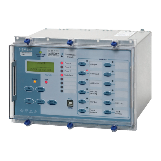
7SR224 Recloser Controller
Overcurrent Relay
Document Release History
This document is issue 2010/05. The list of revisions up to and including this issue is:
2008/03
First Issue
2008/11
Second Issue. Additional I/O connections added
2009/09
Third Issue. Core Balance CT arrangement & Comms options added.
2010/04
Fourth Issue. Check Synchronising added
2010/05
Fifth issue. Document reformat due to rebrand.
Software Revision History
2008/03
2435H80011R2d-1a
2008/06
2435H80011R3d-2b
2008/10
2435H80011R4-3
2009/09
2435H80011R4c-3b
2010/04
2435H80011R4d-4
The copyright and other intellectual property rights in this document, and in any model or article produced from it
(and including any registered or unregistered design rights) are the property of Siemens Protection Devices
Limited. No part of this document shall be reproduced or modified or stored in another form, in any data retrieval
system, without the permission of Siemens Protection Devices Limited, nor shall any model or article be
reproduced from this document unless Siemens Protection Devices Limited consent.
While the information and guidance given in this document is believed to be correct, no liability shall be accepted
for any loss or damage caused by any error or omission, whether such error or omission is the result of
negligence or any other cause. Any and all such liability is disclaimed.
©2010 Siemens Protection Devices Limited
First Release
Second Release. Loss Of Voltage
Third Release. Single/Triple AutoReclose function
Fourth Release. Additional RS485 & RS232 comms
Fifth Release. Check Synchronising
7SR224 Argus Installation
Advertisement
Table of Contents

Related Manuals for Siemens 7SR224


Summary of Contents for Siemens 7SR224
- Page 1 Limited. No part of this document shall be reproduced or modified or stored in another form, in any data retrieval system, without the permission of Siemens Protection Devices Limited, nor shall any model or article be reproduced from this document unless Siemens Protection Devices Limited consent.
-
Page 2: Table Of Contents
Figure 5.4-2 Data Comms to Multiple Devices Using Sigma 3 and F.O. Ring Network ......14 Figure 6.1-1 7SR224 Connections to OHL Circuit .................15 Figure 6.1-2 7SR224 Connections to OHL Circuit with Core Balance CT ..........16 ©2010 Siemens Protection Devices Limited... -
Page 3: Section 1: Installation
If damage has been sustained a claim should immediately be made against the carrier, also inform Siemens Protection Devices Limited, and the local Siemens agent, using the Defect Report Form in the Maintenance section of this manual. -
Page 4: Fibre Optic Communication
Front Cover The front cover provides additional securing of the relay element within the case. The relay cover should be in place during normal operating conditions. ©2010 Siemens Protection Devices Limited Chapter 5 Page 4 of 16... -
Page 5: Section 2: Dimensions And Panel Fixings
The following drawing is available which gives panel cut-out and mounting details. Overall Dimensions and panel Drilling for Size E10 Epsilon case (Typically 5.89Kg) Overall Dimensions and Panel Drilling for Size E12 Epsilon Case ©2010 Siemens Protection Devices Limited Chapter 5 Page 5 of 16... -
Page 6: Fixings
Typical rear terminal block fixing kit (1kit per terminal block fitted to relay) Consists of: 28 x M4, 8mm Screws 28 x M4 Lock Washer 2.2.3 Fibre Optic Connectors The relay has Fibre-Optic ST (BFOC/2.5) bayonet connectors fitted when specified. ©2010 Siemens Protection Devices Limited Chapter 5 Page 6 of 16... -
Page 7: Section 3: Rear Terminal Drawings
E10 STANDARD COMMS i.e. USB FRONT PORT, RS485 (SEE NOTE 2) E10 STANDARD COMMS + ADDITIONAL FIBRE OPTIC PORTS + IRIG-B i.e.:- USB FRONT PORT, RS485 (SEE NOTE 2) IRIG B, 2 X F.O. (S.T. CONNECTORS) ©2010 Siemens Protection Devices Limited Chapter 5 Page 7 of 16... - Page 8 SCREENED, TWISTED PAIR CABLE. ON SITE WHEN WIRING OTHER FACILITIES ENSURE THAT THESE TERMINALS AND OTHER COMMUNICATIONS INTERFACES ARE NOT OBSCURED BY OTHER WIRING RUNS. CABLE SHOULD BE RS485 COMPLIANT. ©2010 Siemens Protection Devices Limited Chapter 5 Page 8 of 16...
-
Page 9: Section 4: Connection/Wiring/Diagrams
7SR224 Argus Installation Section 4: Connection/Wiring/Diagrams Wiring Diagram: 7SR224 Recloser Controller Relay 7SR224 BI 4 BO 7 BI 5 BO 8 Data Comms (Optional) (Optional) (Optional) Analogue BI 6 BO 9 BI 7 BO 10 BO 11 Rear View BI 8... -
Page 10: Figure 4.1-2 Additional Inputs & Outputs Wiring Diagram: 7Sr224
BO 22 BI 21 BI 41 BI 31 BI 42 BI 22 BI 32 BI 43 BI 23 BI 33 Figure 4.1-2 Additional Inputs & Outputs Wiring Diagram: 7SR224 ©2010 Siemens Protection Devices Limited Chapter 5 Page 10 of 16... -
Page 11: Interface Diagram: 7Sr224 Recloser Controller Relay
7SR224 Argus Installation Interface Diagram: 7SR224 Recloser Controller Relay Figure 4.2-1 Interface Diagram: 7SR224 ©2010 Siemens Protection Devices Limited Chapter 5 Page 11 of 16... -
Page 12: Section 5: Data Comms Connections
RS485 Screened Rear terminals Rear terminals twisted pair twisted pair RS 485 Twisted pair screened Cable Control System RS485 RS485 RS485 Figure 5.1-1 RS485 Data Comms Connections Between Relays ©2010 Siemens Protection Devices Limited Chapter 5 Page 12 of 16... -
Page 13: Rs232 Connections
Control System 62.5/125µm fibre optic with ST 25 pin male D connectors connector Figure 5.4-1 Data Comms to Multiple Devices Using Sigma 1 and F.O. Star Network ©2010 Siemens Protection Devices Limited Chapter 5 Page 13 of 16... -
Page 14: Figure 5.4-2 Data Comms To Multiple Devices Using Sigma 3 And F.o. Ring Network
Figure 5.4-2 Data Comms to Multiple Devices Using Sigma 3 and F.O. Ring Network The fibre optic data comms link will be broken if the relay element is withdrawn from the case. ©2010 Siemens Protection Devices Limited Chapter 5 Page 14 of 16... -
Page 15: Section 6: Connection Diagrams
L1, L2 & L3. 5) Bus side Voltage Config:- for optional Synchronising function. Vbn shown, Van, Vbn, Vcn, Vab, Vbc, or Vca can be used. Figure 6.1-1 7SR224 Connections to OHL Circuit ©2010 Siemens Protection Devices Limited Chapter 5 Page 15 of 16... -
Page 16: Figure 6.1-2 7Sr224 Connections To Ohl Circuit With Core Balance Ct
L1, L2 & L3. 5) Bus voltage connections for optional Check Synchronising feature are not shown. Figure 6.1-2 7SR224 Connections to OHL Circuit with Core Balance CT ©2010 Siemens Protection Devices Limited Chapter 5 Page 16 of 16...