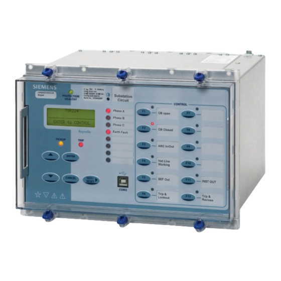
Siemens 7SR224 Argus Manual
Recloser controller
Hide thumbs
Also See for 7SR224 Argus:
- Technical manual (350 pages) ,
- Manual (73 pages) ,
- Description & operation (66 pages)
Table of Contents
Advertisement
Quick Links
Advertisement
Table of Contents

Related Manuals for Siemens 7SR224 Argus


Summary of Contents for Siemens 7SR224 Argus
- Page 1 Reyrolle Protection Devices 7SR224 Argus Recloser Controller Energy Management.
-
Page 2: Function Overview
Single /Triple Pole Autoreclose for Three Single Pole Circuit Breakers User Interface 20 character x 4 line backlit LCD Menu navigation keys 3 fixed function LEDs 8 or 16 Programmable Tri-colour LEDs 12 Programmable Function Keys with Tri-colour LEDs Siemens Protection Devices Limited... -
Page 3: Monitoring Functions
SIARFIx, SMARFIx, STARFIx and Interruption Events,) Viewing and changing settings Binary Input status indication Binary Output status indication Virtual internal status indication Communications Meters Miscellaneous Meters, Date, Time, Waveform, Fault, Event & Data Log records-counters. Demand Monitoring Siemens Protection Devices Limited... -
Page 4: Description Of Functionality
67/50SEF Sensitive Earth Fault Provide Directional Instantaneous or Definite Time (DTL) earth fault protection, with independent settings for pickup current and time-delay. Four elements are provided. Elements can be Inrush-inhibited Siemens Protection Devices Limited... - Page 5 The measured earth fault input may be used in a 64H high- Where second harmonic current is detected i.e. during impedance, restricted earth fault scheme. The required transformer energisation the user selected elements can be external series stabilising resistor and shunt non-linear blocked Varistor can be supplied. Siemens Protection Devices Limited...
- Page 6 A slip-in label pocket along-side enables the user to insert his own notation. A printer compatible template is available. Siemens Protection Devices Limited...
- Page 7 Data Log which can be downloaded for further analysis. A typical application is to record 15 minute intervals over the last 7 days. Siemens Protection Devices Limited...
- Page 8 Evolution and also provides project management of multiple devices to allow engineering of IEC61850 projects. It also provides access to user logic within the devices via an easy to use graphical interface. Fig 3. Typical Reydisp Manager screenshots Siemens Protection Devices Limited...
-
Page 9: Technical Data
IEC 60255-21-3 Class I Allowable superimposed ac 12% of DC voltage component Type Level Variation Allowable breaks/dips in 20ms ≤ 5 % Seismic response 1 gn supply (collapse to zero) Mechanical Classification Auxiliary supply: Burdens >10 Durability operations Siemens Protection Devices Limited... -
Page 10: Electrical Tests
1.0 kV* For full technical data refer to the Performance Specification Line to Line Section of the Technical Manual. *Note 45ms DTL pick up delay applied to binary inputs Conducted Radio Frequency Interference Immunity IEC 60255-22-6 Siemens Protection Devices Limited... - Page 11 Setting Range Is 0.05,0.10…5.0 x In Inhibited by Binary or Virtual Input Operate Level 100% Is, ±5% or ±1%xIn Delay Setting td 0.00,0.01…20,20.5…100,101… 1000,1010…10000,10100…144 Basic Operate Time: 1.1 to 0.5 x Is 35 ms ±10 ms Siemens Protection Devices Limited...
- Page 12 VT Supervision 0 to 5 xIs 35ms ±10ms Inhibited by Binary or Virtual Input 51V Voltage Controlled Overcurrent Setting Range 5,5.5…200V Operate Level 100% Vs, ±5% or ±1%xVn Multiplier 0.25.0.3…1 x Is(51) Inhibited by VT Supervision Siemens Protection Devices Limited...
-
Page 13: Case Dimensions
M4 CLEARANCE (TYPICALLY 4.5 DIAMETER) AND RELAYS MOUNTED USING M4 MACHINE SCREWS, NUTS AND LOCKWASHERS (SUPPLIED IN PANEL FIXING KIT). THE RETAINING SCREW AT THE REAR OF THE CASE FOR THE ETHERNET VARIANT MUST BE FITTED FOR THE DEVICE TO COMPLY WITH PERFORMANCE CLAIMS. Fig 5. E12 Case Siemens Protection Devices Limited... - Page 14 BI 22 BI 23 BI 33 NOTES BI = Binary Input BO = Binary Output Shows contacts internal to relay case assembly. Contacts close when the relay chassis is withdrawn from case Fig 6. 7SR224 Wiring Diagram Siemens Protection Devices Limited...
- Page 15 Switch Unit BI 2 BI - Reclose Block BO - Battery Driver Apply Test & BI 3 BO 4 Monitoring BO - Capacitor Start Test BO 5 Screen BO 6 Term. Fig 7. 7SR224 Interface Diagram Siemens Protection Devices Limited...
- Page 16 (x2) (x4) as derived or Vx (x4) Batt (x2)* Test (x4) (x3) Cap. Test (x4) (x4) & V voltage inputs are optional. 1x 27/59 element is provided in 4xVT variants. (x4) Fig 8. 7SR224 Function Diagram Siemens Protection Devices Limited...
- Page 17 Region World, 50/60Hz, language English, (language changeable) Reyrolle fascia Region World, 50/60Hz, language English, (language changeable) Siemens fascia Region USA, 60/50Hz, language English-US (ANSI), (language changeable), Siemens fascia Communication Interface Standard version - included in all models, USB front port, RS485 rear port...
- Page 18 Ordering Information – 7SR224 Argus Recloser Controller 13 14 15 16 7 S R 2 ORDER-No.: Protection Function Packages Standard version - included in all models 21FL Fault Locator 27/59 Under/overvoltage 27/59 Under/overvoltage, Sag/swell Undercurrent 46BC Broken conductor/load unbalance 46NPS...
- Page 19 Siemens Protection Devices Limited...
- Page 20 Siemens Protection Devices Limited P.O. Box 8 North Farm Road Hebburn Tyne & Wear NE31 1TZ United Kingdom Phone: +44 (0)191 401 7901 Fax: +44 (0)191 401 5575 E-mail: marketing.spdl.gb@siemens.com EMEA-C10031-00-76GB September 2015 For enquires please contact our Customer Support Center...