
Related Manuals for Electrolux thermaline ProThermetic


Summary of Contents for Electrolux thermaline ProThermetic
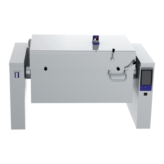
- Page 1 Tilting pressure braising ProThermetic PUET electric Installation and operating manual * 599A1AR01 - 87.8030.01- 2022.11 *Original instructions...
- Page 2 Foreword Read the following instructions, including the warranty terms before installing and using the appliance. Visit our website www.electroluxprofessional.com and open the Support section to: Register your product Get hints & tips of your product, service and repair information The installation, use and maintenance manual (hereinafter Manual) provides the user with information necessary for correct and safe use of the appliance.
-
Page 3: Table Of Contents
Contents A WARNING AND SAFETY INFORMATION....................5 General information ........................5 Personal protection equipment ......................5 General safety ..........................6 ProThermetic general safety ......................6 Protection devices installed on the appliance ..................7 Safety signs to be placed on the appliance or near its area ..............7 Reasonably foreseeable improper use .................... - Page 4 Water filling automatic for “Sprint“ models only .................. 23 NORMAL APPLIANCE USE ........................23 Characteristics of personnel enabled to operate on the appliance ............23 Basic requirements for appliance use....................23 PRODUCT DESCRIPTION ........................23 Use ............................23 Appliance overview ........................23 Control panel ..........................
-
Page 5: Awarning And Safety Information
WARNING AND SAFETY INFORMATION General information To ensure safe use of the appliance and a proper understanding of the manual it is necessary to be familiar with the terms and typographical conventions used in the documentation. The following symbols are used in the manual to indicate and identify the various types of hazards: WARNING Danger for the health and safety of operators. -
Page 6: General Safety
Stage Protective Safety footwear Gloves Glasses Safety helmet garments ○ ● ● — — Scrapping Key: ● PPE REQUIRED ○ PPE AVAILABLE OR TO BE USED IF NECESSARY — PPE NOT REQUIRED During these operations, gloves must be cut-resistant. Failure to use the personal protection equipment by operators, specialized personnel or users can involve exposure to damage to health (depending on the model). -
Page 7: Protection Devices Installed On The Appliance
• In pressure appliances, after cooking with the lid closed, first release the pressure from the cooking chamber and do not open the lid until the pressure is completely exhausted inside the appliance. Protection devices installed on the appliance Guards The appliance has: •... -
Page 8: Transport, Handling And Storage
To preserve these conditions, the areas around the appliance must always be: • kept free of obstacles (e.g. ladders, tools, containers, boxes, etc.); • clean and dry; • well lit. For the Customer's complete information, the residual risks remaining on the appliance are indicated below: such actions are deemed improper and therefore strictly forbidden. -
Page 9: Positioning
• Do not spray water or use water jets, steam cleaner or high pressure cleaner. A.16 Preventive Maintenance In order to ensure the safety and performance of your equipment, it is recommended that service is undertaken by Electrolux Professional authorised engineers every 12 months, in accordance with Electrolux Professional Service Manuals. Please contact your local Electrolux Professional Service Centre for further details. -
Page 10: Bwarranty Terms And Exclusions
– plumbing parts, components or consumable cleaning subject to local terms and conditions. products that are not approved by the manufacturer; Check on Electrolux Professional website the list of authorized customer care. TECHNICAL DATA Data plate position... -
Page 11: How To Interpret The Factory Description
How to interpret the factory description 7 - Power supply electric The factory description on the data plate has the following meaning: electric with core temperature probe 8 - Configuration floorstanding, depth 800 mm, height 700 mm floorstanding, depth 850 mm, height 700 mm floorstanding, depth 900 mm, height 700 mm floorstanding, depth 800 mm, height 800 mm floorstanding, depth 900 mm, height 800 mm... -
Page 12: Testing And Inspection
Any supplements to the installation, use and maintenance Manufacturer Electrolux Professional SpA or any other manual the Customer receives from the Manufacturer will form service centre authorised by Electrolux an integral part of the manual and therefore must be kept Professional SpA. -
Page 13: Einstallation Diagrams
• have a flat support surface to avoid deforming the appliance or damage to the support feet. INSTALLATION DIAGRAMS Installation type • on steel bases • on concrete plinth The appliance must always be installed in its intended location 3. Wall mounted according to the relevant installation and connection diagrams (E INSTALLATION DIAGRAMS). -
Page 14: Dimensions
The tanks are normally cemented in the floor. 1200 1200 Freestanding Against the wall E.3.2 Dimensions 60 l 90 l 100 l 170 l 1200 1200 1600 1600... -
Page 15: Installation And Connection Diagram
Installation and connection diagram Floor mounted appliances 1200 EI = Electrical connection HWI = Hot water connection D = Drain CWI = Cold water connection 60 L 90 L 100 L 170 L 1200 1200 1200 1200 1200 1200 1600 1600 1600 1600... - Page 16 Wall mounted appliances 50 60 50 1200 EI = Electrical connection HWI = Hot water connection D = Drain CWI = Cold water connection 60 L 90 L 100 L 170 L 1200 1200 1200 1200 1200 1200 1600 1600 1600 1600 1600...
-
Page 17: Accessing The Appliance's Internal Components
Accessing the appliance’s internal components INSTALLATION AND ASSEMBLY Introduction • prearrange a device lockable in the open position for the connection to the power supply. WARNING • Do not install the unit in environments where temperatures may fall below 0℃ [32℉] or rise above 40℃ [104℉]. Refer “WARNING SAFETY INFORMATION“. -
Page 18: Installing On Plinth Or Adjustable Feet
Installing on plinth or adjustable feet Polyethylene NOTE! • Outer wrapping If installing on a steel plinth or adjustable feet, • Instructions bag always make sure these are attached to the appliance beforehand. There are no tools for taking the unit down from the transport pallet and Polypropylene putting it in place;... -
Page 19: Wall Installation
Bring the lifting cart as close as possible to the appliance. 2. Carefully turn the unit on shelf A of the truck to the horizontal position and remove the transport pallet. ø10 ø10 Wall installation F.8.1 Preparing the brackets and set up 3. -
Page 20: Sealing
1. First remove the knob, refer to paragraph E.5 Accessing 4. Reassemble the user interface panel and the front panel the appliance’s internal components. by fixing them with screws. Then remove the user interface panel and the front panel by undoing the screws at the bottom. F.10 Sealing 2. -
Page 21: Gelectrical Installation
ELECTRICAL INSTALLATION WARNING The interface for power optimization is in compliance with DIN 18875. Refer “WARNING SAFETY INFORMATION“. Power cable Unless otherwise specified, our appliances are not equipped Mains connection with a power cable. The installer must use a flexible cable having characteristics not lower than the H05RN-F rubber WARNING insulated type. -
Page 22: Mixing Tap
Mixing tap I. Fixing nut J. Gasket Install the mixing tap on the left cover, depending on the model. K. Copper pipes Model 1: Installation: 1. Fasten the clamping collar G with the fixing nut I and gasket below J on the pre-drilled hole of the left cover. 2. -
Page 23: Water Filling Automatic
Water filling automatic • Through the red knob, you can manually run hot water. The automatic water filling system, if available on your model, With hot or cold water filling option: fills up the appliance with a volume of water set by means of •... -
Page 24: Control Panel
4. Touch control panel Carefully pull out the spray gun handle with the hose and snap it into 5. USB connection place. Then press the button to clean 6. Main switch (if available in your model) the device with water. To feed the 7. -
Page 25: Main Menu
K.3.2 Main menu K.3.3.2 Set the power levels (where available) The appliance allows cooking in different cooking modes, store and recall programs. 1. Touch symbol of the temperature value Manual 2. Touch the symbol of power level on the numeric Data Monitor keypad appearing on the display;... -
Page 26: Drawer Area
NOTE! Insert Program name: To store the phase sequence in a program, tap the symbol and refer to paragraph K.3.5 Addi- ABC abc tional functions. K.3.4 Drawer area The drawer is an expansion located inside several environ- ments of the menu and includes options and functions. The lower drawer contains further settings, accessory man- agement and advanced features. - Page 27 K.3.5.5 Pressure cooking options Manual Manual NOTE! Phase Phase Pressure cooking can only take place if the lid is hermetically closed and there is enough water inside, which generates the necessary amount of 50° steam to create enough pressure. Refer to para- graph K.5 Pressure cooking.
-
Page 28: Programs Mode
To select the heating zone: • Download/upload programs: 1. Touch the icon of braising cooking mode to open the 1. To open the lower drawer touch multizone menu; 2. Select one of the four zone options: 2. Choose the icon to download programs, or the icon to upload programs. -
Page 29: Start A Cooking Cycle
NOTE! 3. Touch to close the lower drawer and start the If B function is available for your model, enable it program. referring to K.3.9 Settings paragraph, otherwise: NOTE! 1. Touch the symbol to open the phases menu; If you start a guided program as is, a pop-up appears asking if you want to modify the preset 2. - Page 30 E. Food safety scroll buttons The HACCP feature allows the storage of all the set values identifying a cooking process, and their variation, start/end buttons of scrolling the cavity temperature and, when used, the food core temperature at specific intervals. Service maintenance This environment is only allowed to an authorized HACCP...
-
Page 31: Alarm Messages
H. Manual Touch screen calibration This setting allows to enable / disable the manual cooking This setting allows to set the calibration of the mode and its options: screen. Settings • Touch the screen as close as possible to the centre of the red cross;... -
Page 32: Pressure Cooking
2. Place the Ethernet cable inside the cable gland. 9. Set parameter no. 40 according to the "Parameter Setting" document. Settings Appliance parameters ADDR Isolated RS485 port address Minimum: Default: Maximum: PARAMETER SETTINGS PARAMETER SETTINGS 3. Reassemble the cable gland in its original position. CANCEL NOTE! To check if all parameters are set correctly, refer to... -
Page 33: Safety Valve On The Lid
• By default, the pressure is automatically reduced after a K.6.1 Dismantling and cleaning of safety valve pressure cooking process, but the safety valve on the lid WARNING can also be opened manually taking the appropriate care by turning the lever C from the closed position (in the middle) to Work on the safety valve may the open position (left or right). -
Page 34: Dismounting The Drain Tap Cover
K.7.3 Dismounting the drain tap cover Refer to the paragraph J.2 Appliance overview. Before tilting the appliance, make sure that: • The swivel arm of the mixing tap (if present) is facing forward; • The lid is fully open; • There are no people or objects in the tilting area underneath the appliance. -
Page 35: Daily Cleaning
Drain tap It is possible to develop or regenerate the passive layer by treating it with running, oxygen-rich water. If the cooking appliance has a drain tap, this must be cleaned Oxygen-starving abrasives such as hydrochloric acid, chlor- and grease every day after the last use of the appliance, ides and spice concentrates, mustard, vinegar essences, depending on the frequency of use: spice cubes and cooking salt solutions can lead to chemical... -
Page 36: Maintenance Intervals
IMPORTANT • Repairs and service on the appliances must be carried out when heating elements have cooled down. • Any internal electrical wiring in the appliance and the connections to the earth cable are in accordance with the respective wiring diagrams and must not be modified. -
Page 37: Nappliance Disposal
Anomaly Possible causes Actions EOTS2 Internal sensor overtemperature Cool the appliance before cooking. EOTS3 Cool the appliance by removing steam Internal sensor overtemperature EOTS4 before cooking. Allow appliance to cool before cooking. Temperature too high on electronic ESCH If error persist, contact Customer Care power board Service. - Page 40 Electrolux Professional AG Allmendstrasse 28 CH - 6210 Sursee www.electroluxprofessional.com...