Bosch FPE-8000-SPC/PPC/FMR, FPE-2000/PPC - AVENAR panel 8000/2000 Quick Guide
- Installation manual (113 pages) ,
- User manual (94 pages) ,
- Manual (96 pages)
Advertisement
- 1 Panel overview
- 2 Status LEDs
- 3 What to do in case of an alarm
- 4 Evacuation
- 5 Resetting an alarm
- 6 What to do in case of a fault
- 7 Log on and log off
- 8 Programmable elements
- 9 Change time and date
- 10 Day- and night mode
- 11 Switching off internal buzzer
- 12 Display history
- 13 Select language
- 14 Further information
- 15 Documents / Resources
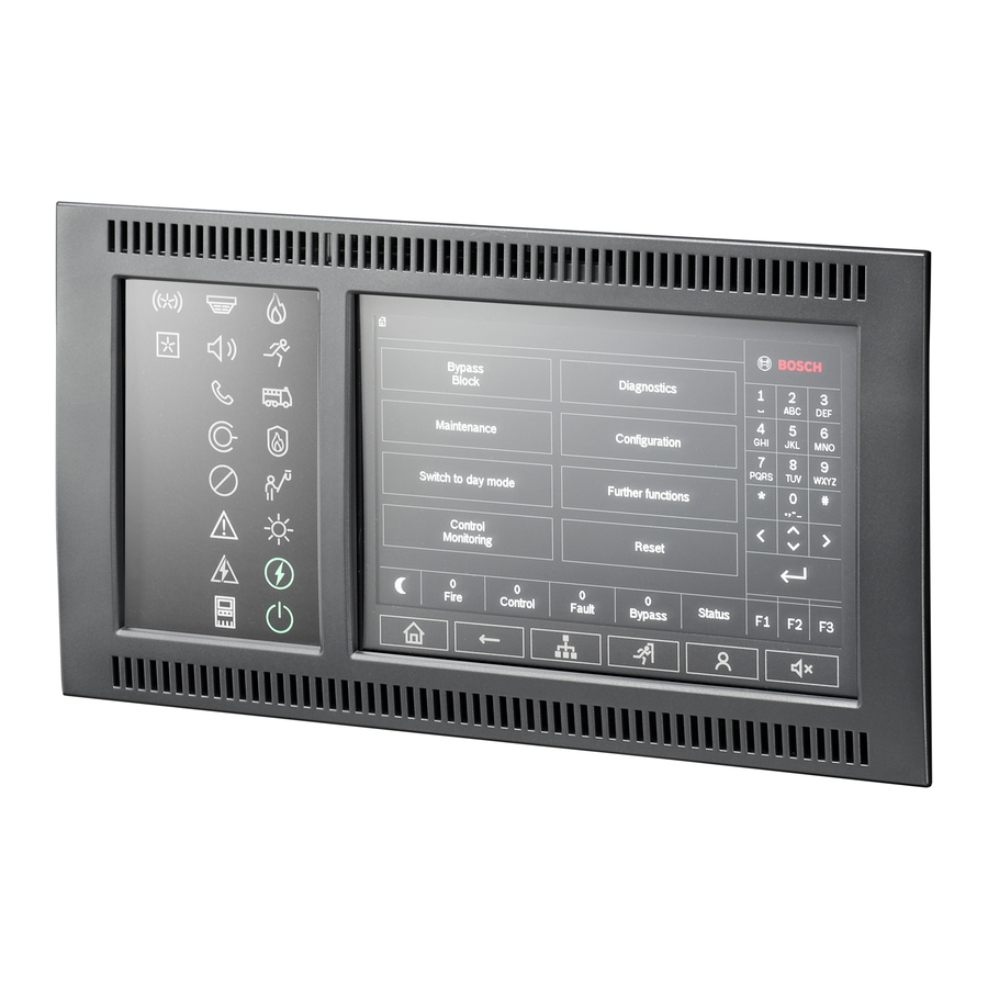
Panel overview

Do not use any pointed or sharp objects when operating the touch-sensitive display. The touchscreen must not be exposed to direct sunlight.

- Status LEDs
- Information bar
- Status bar
- Open start menu
- Go back
- Display a list of the networked panels and establish a remote connection with a networked panel
- Display and control all alarm zones
- Log-in to the panel and call up personalized menu
- Silence internal buzzer
- Function keys, programmable
- Display support information
Status LEDs
| Color* | Meaning | |
 | R | Fire alarm |
 | R | Evacuation ongoing |
 | R | Fire alarm transmission activated |
 | R | Fire protection equipment activated |
 | Y | Maintenance mode |
 | Y | Day mode/delays active |
 | Y | General disabled |
 | Y | General fault |
 | Y** | Fire detector fault / disabled |
 | Y** | Signaling device fault / disabled |
 | Y** | Alarm transmission device fault / disabled |
 | Y** | Output to fire protection equipment fault / disabled |
 | Y | Power fault |
 | G | Power available |
 | Y | System/panel fault |
 | G | System in operation |
 | R | Programmable LED for a self-defined alarm |
 | Y** | Programmable LED for a self-defined fault/diasablement |
| *Y=yellow, R=red, G=green **blinking: fault, steady: disabled | ||
What to do in case of an alarm

- Message type
- Description of the location of the triggering detector
- Address (logical zone and subaddress) of the detector which triggered the alarm
- Number of detectors which triggered the alarm
- Message number
- Number of groups that have triggered a fire alarm and outputs that are activated
Select Acknowledge to start the investigation time (depending on the configuration). During this time, check the message in the place where the detector generating the alarm is located to ensure it is correct.

If you determine during the verification that the alarm is genuine, either trigger an alarm manually by pressing Manual alarm or by activating a manual call point. The evacuation is starting and the transmission device to the fire department is activated.
If you recognize a false alarm, select Reset and log in to the panel to prevent the activation of the transmission device and signaling devices.
 Note: If the investigation time passes by without any further user input (alarm trigger or reset) the evacuation and the transmission to the fire department are activated automatically.
Evacuation

Press the evacuation button to open the list with all available evacuation zones.
To search for a specific zone, enter the number of a group of notification appliances and press  .
.

The background colors of the groups have the following meaning:
- Red: Groups which are actively being controlled in case of an alarm
- Fuchsia: Groups which are actively being controlled without a real alarm, e.g. in case of a fire drill
- Green: Groups which are not active
- Yellow: Groups in fault or disabled, no control is possible.

Select the required group to start or stop the evacuation of this zone immediately. Use  and
and  to scroll through the list. The group entries change their background color according to their current state.
Select All On to control all evacuation groups or All Off to stop the activation of all groups at a time.
Resetting an alarm

- Press Acknowledge.
- Press Signals off.
The sounders and/or optical signaling devices are switched off. - Press Reset.

If a message is marked with an R, the resetting process is not yet complete for this element.
To reset a manual call point, use the reset key or replace the glass window.
To reset an automatic detector: If there is still smoke in the detection chamber please ventilate.
On the next alarm message, all signaling devices that have been switched off are switched back on automatically.
What to do in case of a fault

- Message type
- Element type (corresponding to the second yellow fault status LED)
- Address (logical zone and subaddress) of the element which triggered the fault
- Message number
- Description of the location of the triggering element
- Number of elements which triggered the fault
In case that the panel is showing a fault message with yellow background in combination with a yellow shining  LED and the fault LED
  ,
,  ,
, ,
,  ,
,  or
or  corresponding to the element type (2) in the fault message:
- Press Acknowledge to silence the buzzer
- Press Reset.
- If the fault cannot be reset, please call your installer:
| Name | Telephone number |
Log on and log off

Press  to log on to the panel with your user ID and password. Depending on your access authorization level (2-4), you can use only particular functions.
The default password is "000000", please ask your installer to change this password.
Note: The panel controller may only be operated by trained personnel. The personal access code (consisting of user ID and password) must not be made known to third parties.

If you are already logged on, press  to open the pre-configured personalized menu. To log off, press again and confirm with OK .
Programmable elements
Function keys
There are three functions keys which are freely programmable with frequently used functions of the panel. If a function key is active it is marked with a green bar. Please ask your installer to enter the configured function of the respective key here:

Alarm and fault status LEDs
There are two status LEDs which are programmable for a self-defined alarm and self-defined fault/disablement. Please ask your installer to describe the configured device and status of the respective LED here:

Change time and date
To change the date and time of the panel press  - Further functions - Change date / time and enter the correct values via the keypad.
Day- and night mode
The manner in which an incoming alarm is handled depends on whether the system is in day or night mode.
Night mode has the highest security level. Depending on the configuration, the alarm message is generally transmitted to the fire department without a delay. Signaling devices and transmission devices to the fire department or fire protection systems are activated.
If a panel is set to day mode, it is possible to delay the transmission of the first alarm signal to prevent false alarms. Therefore an alarm must be acknowledged within a certain time. The transmission device to the fire department is not activated in this case. During the delay, the cause of the alarm message can be checked within a configured investigation time to ensure it is correct.
If the investigation time passes by without any further user input (alarm trigger or reset) the transmission to the fire department is activated automatically.
The following symbols on the status bar show which mode the panel is switched to. In the case of networked panels, a night-/day combination icon is displayed on panels in night mode, if at least one panel in the network is in day mode.
| Standalone | Network | ||
 | Night mode | Panel is in night mode | All networked panels in the network scope are in night mode |
 | Day mode | Panel is in day mode | - |
 | Night-/day combination | - | Panel is in night mode but at least one other panel in the network scope is in daymode |
To switch between day- and night mode press the current symbol in the status bar and select either Switch to day mode or Switch to night mode.

Switching off internal buzzer

- Press
![]() to temporarily switch off the internal buzzer.
to temporarily switch off the internal buzzer.
 to temporarily switch off the internal buzzer.
Display history
In the history log, all data about particular events or device types is stored sorted by date and time. To display only particular data, filters can be set.
To show the history log press - Diagnostics History log.
Select language
Press to access the main menu. Press "1" on the alphanumeric keypad. Confirm the appearing query with OK and select the required language from the list.
Further information
For detailed information on the operation of the fire panel please refer to www.boschsecurity.com.
Bosch Sicherheitssysteme GmbH
Robert-Bosch-Ring 5
85630 Grasbrunn Germany
www.boschsecurity.com
© Bosch Sicherheitssysteme GmbH, 2020

Documents / Resources
References
Download manual
Here you can download full pdf version of manual, it may contain additional safety instructions, warranty information, FCC rules, etc.
Download Bosch FPE-8000-SPC/PPC/FMR, FPE-2000/PPC - AVENAR panel 8000/2000 Quick Guide
Advertisement
Thank you! Your question has been received!


Need Assistance?
Do you have a question about the FPE-8000-SPC that isn't answered in the manual? Leave your question here.