Table of Contents
Advertisement
Quick Links
SIPROTEC 5
Hardware Description
V8.83 and higher
Manual
C53000-G5040-C002-M
Preface
Table of Contents
Introduction
Forms of Devices and On-Site Operation
Panels
Electronic Modules
Plug-In Modules
Working on the Device
Technical Data
Ordering Information
Appendix
Literature
Glossary
Index
1
2
3
4
5
6
7
A
Advertisement
Table of Contents

Related Manuals for Siemens SIPROTEC 5 V8.83


Summary of Contents for Siemens SIPROTEC 5 V8.83
- Page 1 Preface Table of Contents Introduction Forms of Devices and On-Site Operation SIPROTEC 5 Panels Hardware Description Electronic Modules Plug-In Modules V8.83 and higher Working on the Device Manual Technical Data Ordering Information Appendix Literature Glossary Index C53000-G5040-C002-M...
- Page 2 Document version: C53000-G5040-C002-M.04 Trademarks Edition: 12.2021 SIPROTEC, DIGSI, SIGRA, SIGUARD, SIMEAS, SAFIR, SICAM, Version of the product described: V8.83 and higher and MindSphere are trademarks of Siemens. Any unauthor- ized use is prohibited.
-
Page 3: Preface
Preface Purpose of the Manual This manual describes the hardware of the SIPROTEC 5 device family and provides general information on the product structure, the modules and technical data. Target Audience Protection system engineers, commissioning engineers, persons entrusted with the setting, testing and main- tenance of automation, selective protection and control equipment, and operational crew in electrical installa- tions and power plants. - Page 4 EN 60255-26 (for EMC directive), the standard EN 50581 (for RoHS directive), and with the product standard EN 60255-27 (for Low Voltage Directive) by Siemens. The device is designed and manufactured for application in an industrial environment.
- Page 5 You can find the product with the UL File Number E194016. IND. CONT. EQ. 69CA Additional Support For questions about the system, contact your Siemens sales partner. Customer Support Center Our Customer Support Center provides a 24-hour service. Siemens AG Smart Infrastructure –...
- Page 6 The equipment (device, module) may be used only for such applications as set out in the catalogs and the technical description, and only in combination with third-party equipment recommended and approved by Siemens. Problem-free and safe operation of the product depends on the following: •...
- Page 7 Preface Selection of Used Symbols on the Device Symbol Description Direct current, IEC 60417, 5031 Alternating current, IEC 60417, 5032 Direct and alternating current, IEC 60417, 5033 Earth (ground) terminal, IEC 60417, 5017 Protective conductor terminal, IEC 60417, 5019 Caution, risk of electric shock Caution, risk of danger, ISO 7000, 0434 Protective Insulation, IEC 60417, 5172, Safety Class II devices Guideline 2002/96/EC for electrical and electronic devices...
- Page 8 SIPROTEC 5, Hardware Description, Manual C53000-G5040-C002-M, Edition 12.2021...
-
Page 9: Table Of Contents
Table of Contents Preface................................3 Introduction..............................15 Advantages of SIPROTEC 5 ....................16 Modular Systems and Hardware Characteristics..............17 Forms of Devices and On-Site Operation Panels..................19 Flush-Mounting Devices....................20 2.1.1 Description ......................... 20 Surface-Mounted Devices with Integrated On-Site Operation Panel........29 2.2.1 Description of the Modular Device................ - Page 10 Table of Contents 3.2.4 Input and Output Module IO203.................. 69 3.2.4.1 Description ......................69 3.2.4.2 Terminals.......................70 3.2.5 Input and Output Module IO204.................. 72 3.2.5.1 Description......................72 3.2.5.2 Terminals.......................73 3.2.6 Input and Output Module IO205.................. 75 3.2.6.1 Description ......................75 3.2.6.2 Terminals.......................76 3.2.7 Input and Output Module IO206..................
- Page 11 Table of Contents Power-Supply Module of Non-Modular Devices (7xx81, 7xx82)........125 3.3.1 Power-Supply Module PS101..................125 3.3.1.1 Description......................125 3.3.1.2 Terminals......................126 Input and Output Modules of Non-Modular Devices (7xx81, 7xx82).........129 3.4.1 Function Description of the Input and Output Modules of the Non-Modular Devices... 129 3.4.2 Input and Output Module IO101................
- Page 12 Table of Contents 4.2.5.2 ETH-BA-2EL......................175 4.2.5.3 ETH-BB-2FO......................176 4.2.5.4 ETH-BD-2FO......................176 Measuring-Transducer Modules..................179 4.3.1 Overview........................179 4.3.2 ANAI-CA-4EL......................179 4.3.3 ARC-CD-3FO ......................180 Working on the Device..........................181 First Steps........................182 5.1.1 Electrical Inspection....................182 Expanding Modular Devices.................... 184 5.2.1 Flush-Mounting Devices.................... 184 5.2.1.1 Basic Rules for Expanding..................
- Page 13 Table of Contents Supply Voltage........................226 Binary Inputs........................228 Relay Outputs......................... 230 Light-Emitting Diodes in the On-Site Operation Panel............233 Communication Interfaces....................234 Electrical Tests........................ 237 Mechanical Tests......................240 Environmental Conditions....................241 6.10 Operating Conditions...................... 243 6.11 Reference Conditions and Influencing Variables...............244 6.12 Approvals........................245 6.13 Design Data........................
- Page 14 SIPROTEC 5, Hardware Description, Manual C53000-G5040-C002-M, Edition 12.2021...
-
Page 15: Introduction
Introduction Advantages of SIPROTEC 5 Modular Systems and Hardware Characteristics SIPROTEC 5, Hardware Description, Manual C53000-G5040-C002-M, Edition 12.2021... -
Page 16: Advantages Of Siprotec 5
Introduction 1.1 Advantages of SIPROTEC 5 Advantages of SIPROTEC 5 The devices in the SIPROTEC 5 series are based on the many years of experience gathered with SIPROTEC 4. Extensive improvements have also been integrated. Take note of the differences between the modular and non-modular systems. -
Page 17: Modular Systems And Hardware Characteristics
Introduction 1.2 Modular Systems and Hardware Characteristics Modular Systems and Hardware Characteristics The SIPROTEC 5 series includes both modular and non-modular devices. Modular devices consist of a base module (1/3 of 19 inches) and can be expanded with expansion modules (1/6 of 19 inches). - Page 18 Introduction 1.2 Modular Systems and Hardware Characteristics Hardware Characteristics for Non-Modular Devices (7xx81) A non-modular device always consists of just 1 module (1/3 of 19 inches) and cannot be expanded with expansion modules (1/6 of 19 inches). The hardware characteristics are: •...
-
Page 19: Forms Of Devices And On-Site Operation Panels
Forms of Devices and On-Site Operation Panels Flush-Mounting Devices Surface-Mounted Devices with Integrated On-Site Operation Panel Surface-Mounted Devices with Detached On-Site Operation Panel On-Site Operation Panels SIPROTEC 5, Hardware Description, Manual C53000-G5040-C002-M, Edition 12.2021... -
Page 20: Flush-Mounting Devices
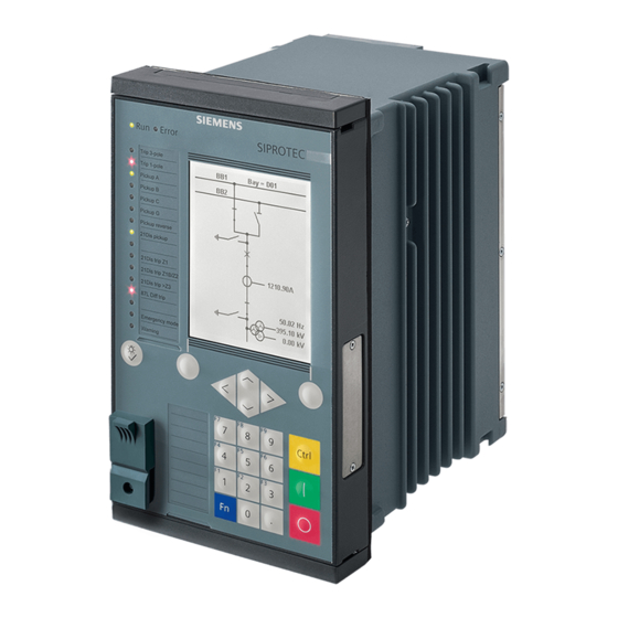
Forms of Devices and On-Site Operation Panels 2.1 Flush-Mounting Devices Flush-Mounting Devices Description 2.1.1 The flush-mounting devices were conceived for installation in 19-inch racks or special openings in control desks and cabinets. The on-site operation panel is linked permanently to the device. Base Module [le_surface_mounting_front, 3, --_--] Figure 2-1... - Page 21 Forms of Devices and On-Site Operation Panels 2.1 Flush-Mounting Devices [le_surface_mounting_front_7SJ81, 1, --_--] Figure 2-2 Front View – 7xx81 USB connection, type B On-site operation panel Bus terminal for expansion module, only possible for modular devices Keypad without function keys SIPROTEC 5, Hardware Description, Manual C53000-G5040-C002-M, Edition 12.2021...
- Page 22 Forms of Devices and On-Site Operation Panels 2.1 Flush-Mounting Devices [le_rear modular device, 3, --_--] Figure 2-3 Rear View of a Modular Device, Terminals of a Typical Device with IO202 Current terminal 1A Spring clip Voltage terminal 1B Voltage terminal 1C Voltage terminal 1D Protective grounding terminals Plug-in module position F...
- Page 23 Forms of Devices and On-Site Operation Panels 2.1 Flush-Mounting Devices [le_rear non modular, 3, --_--] Figure 2-4 Rear View of a Non-Modular Device (7xx81, 7xx82), Terminals of a Typical Device with IO102 Current terminal A Spring clip Voltage terminal B Voltage terminal D Protective grounding terminals Terminal for integrated Ethernet interface J...
- Page 24 Forms of Devices and On-Site Operation Panels 2.1 Flush-Mounting Devices Fastening Openings of the Base and 1/3 Module To remove the screw covers, introduce the screwdriver into the provided slot. [dw_screwdriver, 1, --_--] Figure 2-5 Slot for Introducing the Screwdriver Loosen the cover by turning slightly.
- Page 25 Forms of Devices and On-Site Operation Panels 2.1 Flush-Mounting Devices Expansion Module [le_front expansion module, 1, --_--] Figure 2-7 Front View of the Expansion Module Device housing On-site operation panel Bus terminal for an additional expansion module (shown with bus termination plate) Unused bus terminals are sealed with a cover.
- Page 26 Forms of Devices and On-Site Operation Panels 2.1 Flush-Mounting Devices [le_rear expansion module, 1, --_--] Figure 2-8 Rear View of the Expansion Module Current terminal xA Spring clip Voltage terminal xB Bus terminal to the base module Voltage terminal xC Voltage terminal xD Protective grounding terminals NOTE...
- Page 27 Forms of Devices and On-Site Operation Panels 2.1 Flush-Mounting Devices Counting Method for Modules in 19-Inch Rack (View of the Rear of the Device) [dwbgrpos-170713-01.tif, 3, en_US] Figure 2-9 Counting Method for Modules in 19-Inch Rack (Example) Current terminal A Voltage terminal A, B, C, D Terminal for time synchronization G Plug-in module E, F...
- Page 28 Forms of Devices and On-Site Operation Panels 2.1 Flush-Mounting Devices NOTE The structure of the 2nd device row is described in chapter 5.2.1.3 Expanding Devices with 2nd Device Row. Connection Systems [le_connection, 1, --_--] Figure 2-10 Connection Systems Cut-out for contact tab Contact tab (prefitted on the expansion module) Hinged angle clip Snap-in spring...
-
Page 29: Surface-Mounted Devices With Integrated On-Site Operation Panel
Forms of Devices and On-Site Operation Panels 2.2 Surface-Mounted Devices with Integrated On-Site Operation Panel Surface-Mounted Devices with Integrated On-Site Operation Panel Description of the Modular Device 2.2.1 NOTE The basic device structure is described in chapter 2.1.1 Description The surface-mounting devices with integrated on-site operation panel were conceived for fitting on a flat wall surface. - Page 30 Forms of Devices and On-Site Operation Panels 2.2 Surface-Mounted Devices with Integrated On-Site Operation Panel [dwauzeil-040211-01.tif, 2, --_--] Figure 2-12 Basic and Expansion Module of the Surface-Mounting Device Mounting bracket NOTE When a base module is expanded, 2 mounting brackets must be fitted between the on-site operation panels and the distance frame.
-
Page 31: Description Of The Non-Modular Surface-Mounted Device
Forms of Devices and On-Site Operation Panels 2.2 Surface-Mounted Devices with Integrated On-Site Operation Panel Fastening Openings [dwbaaube-040211-01.tif, 2, --_--] Figure 2-13 Fastening Openings of the Base Module Top fastening openings Bottom fastening openings 2.2.2 Description of the Non-Modular Surface-Mounted Device NOTE The basic device structure is described in chapter 2.1.1 Description... - Page 32 Forms of Devices and On-Site Operation Panels 2.2 Surface-Mounted Devices with Integrated On-Site Operation Panel [le_device with console above and below, 1, --_--] Figure 2-14 Bracket with the Opening Upward (Left) and the Opening Downward (Right) Flush-mounting device Bracket for the surface-mounting variant Bracket opening for cable entry or exit when mounting or dismantling the device SIPROTEC 5, Hardware Description, Manual C53000-G5040-C002-M, Edition 12.2021...
- Page 33 Forms of Devices and On-Site Operation Panels 2.2 Surface-Mounted Devices with Integrated On-Site Operation Panel [sc device mounting, 2, --_--] Figure 2-15 Surface-Mounted Version of the Non-Modular Device, Mounted SIPROTEC 5, Hardware Description, Manual C53000-G5040-C002-M, Edition 12.2021...
- Page 34 Forms of Devices and On-Site Operation Panels 2.2 Surface-Mounted Devices with Integrated On-Site Operation Panel Fastening Openings [sc fixing console, 2, --_--] Figure 2-16 Fastening Openings of the Bracket SIPROTEC 5, Hardware Description, Manual C53000-G5040-C002-M, Edition 12.2021...
-
Page 35: Surface-Mounted Devices With Detached On-Site Operation Panel
Forms of Devices and On-Site Operation Panels 2.3 Surface-Mounted Devices with Detached On-Site Operation Panel Surface-Mounted Devices with Detached On-Site Operation Panel Description 2.3.1 NOTE The basic device structure is described in chapter 2.1.1 Description The surface-mounted devices with detached on-site operation panel are a variant of the surface-mounted devices with an integrated on-site operation panel. - Page 36 Forms of Devices and On-Site Operation Panels 2.3 Surface-Mounted Devices with Detached On-Site Operation Panel [le_device mounting base module, 2, --_--] Figure 2-17 Device Structure of the Base Module Top fixing bracket Cover Bottom fixing bracket Connecting cable between the base module and the on-site operation panel Rear plate of the on-site operation panel SIPROTEC 5, Hardware Description, Manual C53000-G5040-C002-M, Edition 12.2021...
- Page 37 Forms of Devices and On-Site Operation Panels 2.3 Surface-Mounted Devices with Detached On-Site Operation Panel Fastening Openings [dwbaaube-040211-01.tif, 2, --_--] Figure 2-18 Device Structure of the Base Module Top fastening openings with fastening screw Bottom fastening openings with fastening screw SIPROTEC 5, Hardware Description, Manual C53000-G5040-C002-M, Edition 12.2021...
- Page 38 Forms of Devices and On-Site Operation Panels 2.3 Surface-Mounted Devices with Detached On-Site Operation Panel [dwosobb1-040211-01.tif, 2, --_--] Figure 2-19 Fastening Openings for the On-Site Operation Panel Screw cover (pull towards you to remove) Fastening opening Fastening opening with fastening screw SIPROTEC 5, Hardware Description, Manual C53000-G5040-C002-M, Edition 12.2021...
-
Page 39: On-Site Operation Panels
Forms of Devices and On-Site Operation Panels 2.4 On-Site Operation Panels On-Site Operation Panels Description 2.4.1 Operating Concept The operating concept is based on 4 groups: • Navigation in the menu tree • Modification of settings • Display of measured values and protocols •... - Page 40 Forms of Devices and On-Site Operation Panels 2.4 On-Site Operation Panels [dw_osop_with_pushbutton, 2, --_--] Figure 2-21 Variants 1/6 Views SIPROTEC 5, Hardware Description, Manual C53000-G5040-C002-M, Edition 12.2021...
-
Page 41: Overview Of Operating Elements And Display Elements
Forms of Devices and On-Site Operation Panels 2.4 On-Site Operation Panels Overview of Operating Elements and Display Elements 2.4.2 On-Site Operation Panel of the Base 1/3 Module [le_base_module, 3, --_--] Figure 2-22 Base 1/3 Module in Standard Design, US Design (a), China Design (b), and for 7xx81 (c) Operating state display Display in 2 design versions Keypad with navigation keys... - Page 42 Forms of Devices and On-Site Operation Panels 2.4 On-Site Operation Panels Reset and LED test key (10) 16 two-colored LEDs (for 7xx81: 12 two-colored LEDs) The on-site operation panels are distinguished by the following characteristics: • Flat and compact design •...
- Page 43 Forms of Devices and On-Site Operation Panels 2.4 On-Site Operation Panels Operating Element/ Function Display Element Control key for activating the control display Control key for activating the switching object Control key for deactivating the switching object Display of operability Run: ready to operate, the green LED is lit.
- Page 44 Forms of Devices and On-Site Operation Panels 2.4 On-Site Operation Panels On-Site Operation Panel of Expansion Modules [le_expansion modules, 1, --_--] Figure 2-23 Expansion Module 16 monochrome LEDs Cover labels 2 key switches 8 monochrome LEDs 8 push-buttons The on-site operation panels are distinguished by the following characteristics: •...
- Page 45 Forms of Devices and On-Site Operation Panels 2.4 On-Site Operation Panels Operating Element/ Meaning Display Element 16 monochrome parameterizable LEDs Local: On-site operation Remote: Remote control Interlocking OFF: Unlocked operation Normal: locked operation with the configured interlocking conditions The on-site operation panel with push-buttons is equipped with 8 LEDs and 8 function keys. It can be used as an on-site operation panel by almost all the I/O modules (except for the modules IO230, IO231).
- Page 46 SIPROTEC 5, Hardware Description, Manual C53000-G5040-C002-M, Edition 12.2021...
-
Page 47: Electronic Modules
Electronic Modules Power-Supply Modules of the Modular Devices Input and Output Modules of the Modular Devices Power-Supply Module of Non-Modular Devices (7xx81, 7xx82) Input and Output Modules of Non-Modular Devices (7xx81, 7xx82) SIPROTEC 5, Hardware Description, Manual C53000-G5040-C002-M, Edition 12.2021... -
Page 48: Power-Supply Modules Of The Modular Devices
Electronic Modules 3.1 Power-Supply Modules of the Modular Devices Power-Supply Modules of the Modular Devices Function Description of the Power-Supply Modules of the Modular Devices 3.1.1 Module Designation Function Description • PS201 Power-supply module • Plug-in module assembly • DC 24 V/DC 48 V or DC 60 V to 250 V and AC 100 V to 230 V •... -
Page 49: Terminals
Electronic Modules 3.1 Power-Supply Modules of the Modular Devices 3.1.2.2 Terminals Overview of Terminals [le_ps201, 3, --_--] Figure 3-1 PS201 – Terminals Voltage terminal 2B Time synchronization G Terminal for detached on-site operation panel H Plug-in module position E Integrated Ethernet interface J COM link K, connection to the CB202 plug-in module assembly, position K Plug-in module position F Protective grounding terminals... - Page 50 Electronic Modules 3.1 Power-Supply Modules of the Modular Devices Terminal and Connection Diagram [cdps201x-270912-01.tif, 1, en_US] Figure 3-2 PS201 – Terminal Diagram SIPROTEC 5, Hardware Description, Manual C53000-G5040-C002-M, Edition 12.2021...
- Page 51 Electronic Modules 3.1 Power-Supply Modules of the Modular Devices [tdps201x-270812-01.tif, 1, en_US] Figure 3-3 PS201 – Connection Diagram Time-Synchronization Terminal The terminal for time synchronization is located on the D-sub 9 interface (position G). Time synchronization signals for DC 5 V, DC 12 V, and DC 24 V can be processed as an option. For further information on connecting to the time synchronization, see chapter 6.6 Communication Interfaces in the Technical Data.
-
Page 52: Power-Supply Module Ps203 For The 2Nd Device Row
Electronic Modules 3.1 Power-Supply Modules of the Modular Devices Ethernet COM Link The Ethernet connection to the CB202 plug-in module assembly with integrated power supply is realized using the RJ45 interface. The RJ45 interface can be used exclusively for the connection of the CB202 plug-in module assembly. This terminal is left unused when no CB202 plug-in module assembly is in use. -
Page 53: Terminals
Electronic Modules 3.1 Power-Supply Modules of the Modular Devices 3.1.3.2 Terminals Overview of Terminals [le_ps203, 2, --_--] Figure 3-4 PS203 – Terminals 2-pole terminal to connect power supply LED: Power On Protective grounding terminals Connection Diagram [tdps203x-030713-01.tif, 2, en_US] Figure 3-5 PS203 –... - Page 54 Electronic Modules 3.1 Power-Supply Modules of the Modular Devices [dwkl2pol-030211-01.tif, 1, --_--] Figure 3-6 Connection of External Power Supply NOTE When expanding a device with the 2nd device row, you must install the connecting cable for the 2nd device row with the corresponding angle rail. All required components are included in the scope of delivery of a power-supply module PS203.
-
Page 55: Power-Supply Module Ps204 For Redundant Power Supply
Electronic Modules 3.1 Power-Supply Modules of the Modular Devices Device bus of the outermost right expansion module of the 1st device row Sealing plate Adaptor angle 2 fastening screws [dw_schiene-020414-01, 1, --_--] Figure 3-9 Angle Rail Angle rail 2 rubber seals Power-Supply Module PS204 for Redundant Power Supply 3.1.4 3.1.4.1... - Page 56 Electronic Modules 3.1 Power-Supply Modules of the Modular Devices • 2nd device row: – Mounting position 7: PS203 – Mounting positions 8 to 11: IO2xx – Mounting position 12: PS204 [dw_module_position_PS204, 1, en_US] Figure 3-10 Arrangement of Modules with 2 PS204 Modules – Rear View There is an exception if a CB202 PCB assembly with integrated power supply is to be used: The CB202 PCB assembly with integrated power supply must always be positioned to the right (front view) of the PS204 module in the 1st or 2nd row.
- Page 57 Electronic Modules 3.1 Power-Supply Modules of the Modular Devices Example Installation of the PS204 with a CB202 in a 1-Row Device with 5/6 Configuration • 1st device row: – Mounting position 1: IO2xx – Mounting position 2: PS201 – Mounting position 3: IO2xx –...
-
Page 58: Terminals
Electronic Modules 3.1 Power-Supply Modules of the Modular Devices 3.1.4.3 Terminals Overview of Terminals [le_ps204, 1, --_--] Figure 3-12 PS204 – Terminals 2-pole terminal to connect power supply LED: Power On Protective grounding terminal Connection Diagram [tdps204x, 1, en_US] Figure 3-13 PS204 –... -
Page 59: Plug-In Module Assembly With Integrated Power Supply Cb202
Electronic Modules 3.1 Power-Supply Modules of the Modular Devices [dwkl2pol-030211-01.tif, 1, --_--] Figure 3-14 Connection of External Power Supply Plug-In Module Assembly with Integrated Power Supply CB202 3.1.5 3.1.5.1 Description The plug-in module assembly CB202 is a PCB assembly with an internal power supply. The plug-in module assembly CB202 is used in an expansion module. -
Page 60: Terminals
Electronic Modules 3.1 Power-Supply Modules of the Modular Devices COM Link (RJ45) Signal Color Operating State LED 1 CL2_LED0_N Yellow Flashes when a communication module is inserted in plug-in module position P. LED 2 CL3_LED0_N Green Flashes when a communication module is inserted in plug-in module position N. - Page 61 Electronic Modules 3.1 Power-Supply Modules of the Modular Devices The 2-pole voltage terminal is used for the external power supply (see Figure 3-17). Connection Diagram [tdcb202x-100713-01.tif, 2, en_US] Figure 3-16 CB202 – Connection Diagram [dwkl2pol-030211-01.tif, 1, --_--] Figure 3-17 Connection of External Power Supply SIPROTEC 5, Hardware Description, Manual C53000-G5040-C002-M, Edition 12.2021...
-
Page 62: Input And Output Modules Of The Modular Devices
Electronic Modules 3.2 Input and Output Modules of the Modular Devices Input and Output Modules of the Modular Devices Function Description of the Input and Output Modules of the Modular Devices 3.2.1 Module Designation Function Description • IO201 Input and output module •... -
Page 63: Input And Output Module Io201
Electronic Modules 3.2 Input and Output Modules of the Modular Devices Module Designation Function Description • IO233 Input module with special version for binary inputs. You can find more infor- mation in chapter 6 Technical Data. • 48 binary inputs •... -
Page 64: Terminals
Electronic Modules 3.2 Input and Output Modules of the Modular Devices 3.2.2.2 Terminals Overview of Terminals [dwio201p-030211-01.tif, 2, --_--] Figure 3-18 IO201 – Terminals Current terminal xA Voltage terminal xB Voltage terminal xC Voltage terminal xD Protective grounding terminals NOTE x corresponds to the slot in the 19-inch rack. - Page 65 Electronic Modules 3.2 Input and Output Modules of the Modular Devices Terminal and Connection Diagram For the binary inputs and outputs, the x corresponds to the slot in the 19-inch rack. [cdio201x-290812-01.tif, 1, en_US] Figure 3-19 IO201 – Terminal Diagram SIPROTEC 5, Hardware Description, Manual C53000-G5040-C002-M, Edition 12.2021...
-
Page 66: Input And Output Module Io202
Electronic Modules 3.2 Input and Output Modules of the Modular Devices [tdio201x-290812-01.tif, 1, en_US] Figure 3-20 IO201 – Connection Diagram 3.2.3 Input and Output Module IO202 3.2.3.1 Description The terminals for the following are located on the input and output module IO202: •... -
Page 67: Terminals
Electronic Modules 3.2 Input and Output Modules of the Modular Devices 3.2.3.2 Terminals Overview of Terminals [dwio202p-030211-01.tif, 2, --_--] Figure 3-21 IO202 – Terminals Current terminal xA Voltage terminal xB Voltage terminal xC Voltage terminal xD Protective grounding terminals NOTE x corresponds to the slot in the 19-inch rack. - Page 68 Electronic Modules 3.2 Input and Output Modules of the Modular Devices Terminal and Connection Diagram For the binary inputs and outputs, the x corresponds to the slot in the 19-inch rack. [cdio202x-300812-01.tif, 1, en_US] Figure 3-22 IO202 – Terminal Diagram SIPROTEC 5, Hardware Description, Manual C53000-G5040-C002-M, Edition 12.2021...
-
Page 69: Input And Output Module Io203
Electronic Modules 3.2 Input and Output Modules of the Modular Devices [tdio202x-240812-01.tif, 1, en_US] Figure 3-23 IO202 – Connection Diagram Input and Output Module IO203 3.2.4 3.2.4.1 Description The terminals for the following are located on the input and output module IO203: •... -
Page 70: Terminals
Electronic Modules 3.2 Input and Output Modules of the Modular Devices 3.2.4.2 Terminals Overview of Terminals [le_io203, 1, --_--] Figure 3-24 IO203 – Terminals Current terminal xA Current terminal xB Voltage terminal xD Protective grounding terminals NOTE x corresponds to the slot in the 19-inch rack. SIPROTEC 5, Hardware Description, Manual C53000-G5040-C002-M, Edition 12.2021... - Page 71 Electronic Modules 3.2 Input and Output Modules of the Modular Devices Terminal and Connection Diagram For the binary inputs and outputs, the x corresponds to the slot in the 19-inch rack. [cdio203x-280812-01.tif, 1, en_US] Figure 3-25 IO203 – Terminal Diagram SIPROTEC 5, Hardware Description, Manual C53000-G5040-C002-M, Edition 12.2021...
-
Page 72: Input And Output Module Io204
Electronic Modules 3.2 Input and Output Modules of the Modular Devices [tdio203x-110313-01.tif, 1, en_US] Figure 3-26 IO203 – Connection Diagram Input and Output Module IO204 3.2.5 3.2.5.1 Description The terminals for the following are located on the input and output module IO204: •... -
Page 73: Terminals
Electronic Modules 3.2 Input and Output Modules of the Modular Devices 3.2.5.2 Terminals Overview of Terminals [dwio204p-201112-01.tif, 2, --_--] Figure 3-27 IO204 – Terminals Voltage terminal xA Voltage terminal xC Voltage terminal xD Protective grounding terminals NOTE x corresponds to the slot in the 19-inch rack. SIPROTEC 5, Hardware Description, Manual C53000-G5040-C002-M, Edition 12.2021... - Page 74 Electronic Modules 3.2 Input and Output Modules of the Modular Devices Terminal and Connection Diagram For the binary inputs and outputs, the x corresponds to the slot in the 19-inch rack. [cdio204x-201112-01.tif, 1, en_US] Figure 3-28 IO204 – Terminal Diagram SIPROTEC 5, Hardware Description, Manual C53000-G5040-C002-M, Edition 12.2021...
-
Page 75: Input And Output Module Io205
Electronic Modules 3.2 Input and Output Modules of the Modular Devices [tdio204x-201112-01.tif, 1, en_US] Figure 3-29 IO204 – Connection Diagram Input and Output Module IO205 3.2.6 Description 3.2.6.1 The terminals for the following are located on the input and output module IO205: •... -
Page 76: Terminals
Electronic Modules 3.2 Input and Output Modules of the Modular Devices 3.2.6.2 Terminals Overview of Terminals [dwio205p-030211-01.tif, 2, --_--] Figure 3-30 IO205 – Terminals Voltage terminal xA Voltage terminal xB Voltage terminal xC Voltage terminal xD Protective grounding terminals NOTE x corresponds to the slot in the 19-inch rack. - Page 77 Electronic Modules 3.2 Input and Output Modules of the Modular Devices Terminal and Connection Diagram For the binary inputs and outputs, the x corresponds to the slot in the 19-inch rack. [cdio205x-260213-01.tif, 1, en_US] Figure 3-31 IO205 – Terminal Diagram SIPROTEC 5, Hardware Description, Manual C53000-G5040-C002-M, Edition 12.2021...
-
Page 78: Input And Output Module Io206
Electronic Modules 3.2 Input and Output Modules of the Modular Devices [tdio205x-240812-01.tif, 1, en_US] Figure 3-32 IO205 – Connection Diagram Input and Output Module IO206 3.2.7 3.2.7.1 Description The terminals for the following are located on the input and output module IO206: •... -
Page 79: Terminals
Electronic Modules 3.2 Input and Output Modules of the Modular Devices 3.2.7.2 Terminals Overview of Terminals [dwio206p-030211-01.tif, 2, --_--] Figure 3-33 IO206 – Terminals Voltage terminal xA Voltage terminal xD Protective grounding terminals NOTE x corresponds to the slot in the 19-inch rack. SIPROTEC 5, Hardware Description, Manual C53000-G5040-C002-M, Edition 12.2021... - Page 80 Electronic Modules 3.2 Input and Output Modules of the Modular Devices Terminal and Connection Diagram For the binary inputs and outputs, the x corresponds to the slot in the 19-inch rack. [cdio206x-280812-01.tif, 1, en_US] Figure 3-34 IO206 – Terminal Diagram [tdio206x-050313-02.tif, 1, en_US] Figure 3-35 IO206 –...
-
Page 81: Input And Output Module Io207
Electronic Modules 3.2 Input and Output Modules of the Modular Devices Input and Output Module IO207 3.2.8 3.2.8.1 Description The terminals for the following are located on the input and output module IO207: • 16 binary inputs • 8 binary outputs with 8 standard make contacts (type S) The connections are distributed over four 14-pole voltage terminals. - Page 82 Electronic Modules 3.2 Input and Output Modules of the Modular Devices Terminal and Connection Diagram For the binary inputs and outputs, the x corresponds to the slot in the 19-inch rack. [cdio207x-260213-01.tif, 1, en_US] Figure 3-37 IO207 – Terminal Diagram SIPROTEC 5, Hardware Description, Manual C53000-G5040-C002-M, Edition 12.2021...
-
Page 83: Input And Output Module Io208
Electronic Modules 3.2 Input and Output Modules of the Modular Devices [tdio207x-300812-01.tif, 1, en_US] Figure 3-38 IO207 – Connection Diagram Input and Output Module IO208 3.2.9 3.2.9.1 Description The terminals for the following are located on the input and output module IO208: •... -
Page 84: Terminals
Electronic Modules 3.2 Input and Output Modules of the Modular Devices 3.2.9.2 Terminals Overview of Terminals [dwio208p-030211-01.tif, 2, --_--] Figure 3-39 IO208 – Terminals Current terminal xA Voltage terminal xB Voltage terminal xC Voltage terminal xD Protective grounding terminals NOTE x corresponds to the slot in the 19-inch rack. - Page 85 Electronic Modules 3.2 Input and Output Modules of the Modular Devices Terminal and Connection Diagram For the binary inputs and outputs, the x corresponds to the slot in the 19-inch rack. [cdio208x-050313-01.tif, 3, en_US] Figure 3-40 IO208 – Terminal Diagram SIPROTEC 5, Hardware Description, Manual C53000-G5040-C002-M, Edition 12.2021...
-
Page 86: Input And Output Module Io209
Electronic Modules 3.2 Input and Output Modules of the Modular Devices [tdio208x-300812-01.tif, 1, en_US] Figure 3-41 IO208 – Connection Diagram 3.2.10 Input and Output Module IO209 3.2.10.1 Description The terminals for the following are located on the input and output module IO209: •... -
Page 87: Terminals
Electronic Modules 3.2 Input and Output Modules of the Modular Devices 3.2.10.2 Terminals Overview of Terminals [dwio209p-030211-01.tif, 2, --_--] Figure 3-42 IO209 – Terminals Voltage terminal xA Voltage terminal xC Voltage terminal xD Protective grounding terminals NOTE x corresponds to the slot in the 19-inch rack. SIPROTEC 5, Hardware Description, Manual C53000-G5040-C002-M, Edition 12.2021... - Page 88 Electronic Modules 3.2 Input and Output Modules of the Modular Devices Terminal and Connection Diagram For the binary inputs and outputs, the x corresponds to the slot in the 19-inch rack. [cdio209x-110313-01.tif, 1, en_US] Figure 3-43 IO209 – Terminal Diagram SIPROTEC 5, Hardware Description, Manual C53000-G5040-C002-M, Edition 12.2021...
-
Page 89: Input And Output Module Io210
Electronic Modules 3.2 Input and Output Modules of the Modular Devices [tdio209x-270812-01.tif, 1, en_US] Figure 3-44 IO209 – Connection Diagram Input and Output Module IO210 3.2.11 3.2.11.1 Description The terminals for the following are located on the input and output module IO210: •... -
Page 90: Terminals
Electronic Modules 3.2 Input and Output Modules of the Modular Devices 3.2.11.2 Terminals Overview of Terminals [dwio202p-030211-01.tif, 2, --_--] Figure 3-45 IO210 – Terminals Current terminal xA Voltage terminal xB Voltage terminal xC Voltage terminal xD Protective grounding terminals NOTE x corresponds to the slot in the 19-inch rack. - Page 91 Electronic Modules 3.2 Input and Output Modules of the Modular Devices Terminal and Connection Diagram For the binary inputs and outputs, the x corresponds to the slot in the 19-inch rack. [cd_io210, 3, en_US] Figure 3-46 IO210 – Terminal Diagram Voltage input MT3 with higher voltage immunity (maximum continuous voltage ±...
-
Page 92: Input And Output Module Io211
Electronic Modules 3.2 Input and Output Modules of the Modular Devices [td_io210, 3, en_US] Figure 3-47 IO210 – Connection Diagram 3.2.12 Input and Output Module IO211 3.2.12.1 Description The terminals for the following are located on the input and output module IO211: •... -
Page 93: Terminals
Electronic Modules 3.2 Input and Output Modules of the Modular Devices 3.2.12.2 Terminals Overview of Terminals [dwio211p-211112-01.tif, 2, --_--] Figure 3-48 IO211 – Terminals Voltage terminal xA Voltage terminal xC Voltage terminal xD Protective grounding terminals NOTE x corresponds to the slot in the 19-inch rack. SIPROTEC 5, Hardware Description, Manual C53000-G5040-C002-M, Edition 12.2021... - Page 94 Electronic Modules 3.2 Input and Output Modules of the Modular Devices Terminal and Connection Diagram For the binary inputs and outputs, the x corresponds to the slot in the 19-inch rack. [cdio211x-221112-01.tif, 1, en_US] Figure 3-49 IO211 – Terminal Diagram SIPROTEC 5, Hardware Description, Manual C53000-G5040-C002-M, Edition 12.2021...
-
Page 95: Input And Output Module Io212
Electronic Modules 3.2 Input and Output Modules of the Modular Devices [tdio211x-211112-01.tif, 1, en_US] Figure 3-50 IO211 – Connection Diagram Input and Output Module IO212 3.2.13 3.2.13.1 Description The terminals for the following are located on the input and output module IO212: •... -
Page 96: Terminals
Electronic Modules 3.2 Input and Output Modules of the Modular Devices 3.2.13.2 Terminals Overview of Terminals [dwio204p-201112-01.tif, 2, --_--] Figure 3-51 IO212 – Terminals Voltage terminal xA Voltage terminal xC Voltage terminal xD Protective grounding terminals NOTE x corresponds to the slot in the 19-inch rack. SIPROTEC 5, Hardware Description, Manual C53000-G5040-C002-M, Edition 12.2021... - Page 97 Electronic Modules 3.2 Input and Output Modules of the Modular Devices Terminal and Connection Diagram For the binary inputs and outputs, the x corresponds to the slot in the 19-inch rack. [cd_io212, 2, en_US] Figure 3-52 IO212 – Terminal Diagram SIPROTEC 5, Hardware Description, Manual C53000-G5040-C002-M, Edition 12.2021...
-
Page 98: Input And Output Module Io214
Electronic Modules 3.2 Input and Output Modules of the Modular Devices [tdio212x, 2, en_US] Figure 3-53 IO212 – Connection Diagram Input and Output Module IO214 3.2.14 3.2.14.1 Description The terminals for the following are located on the input and output module IO214: •... -
Page 99: Terminals
Electronic Modules 3.2 Input and Output Modules of the Modular Devices 3.2.14.2 Terminals Overview of Terminals [dwio214p-030211-01.tif, 2, --_--] Figure 3-54 IO214 – Terminals Current terminal xA Voltage terminal xB Voltage terminal xC Voltage terminal xD Protective grounding terminals NOTE x corresponds to the slot in the 19-inch rack. - Page 100 Electronic Modules 3.2 Input and Output Modules of the Modular Devices Terminal and Connection Diagram For the binary inputs and outputs, the x corresponds to the slot in the 19-inch rack. [cdio214x-260213-01.tif, 1, en_US] Figure 3-55 IO214 – Terminal Diagram SIPROTEC 5, Hardware Description, Manual C53000-G5040-C002-M, Edition 12.2021...
-
Page 101: Input And Output Module Io215
Electronic Modules 3.2 Input and Output Modules of the Modular Devices [tdio214x-270812-01.tif, 1, en_US] Figure 3-56 IO214 – Connection Diagram 3.2.15 Input and Output Module IO215 3.2.15.1 Description The terminals for the following are located on the input and output module IO215: •... -
Page 102: Input Module Io216
Electronic Modules 3.2 Input and Output Modules of the Modular Devices Input Module IO216 3.2.16 3.2.16.1 Description The terminals for the following are located on the input and output module IO216: • 16 special binary inputs with maximized robustness against electrical disturbances and failures The connections are distributed over: •... - Page 103 Electronic Modules 3.2 Input and Output Modules of the Modular Devices Terminal and Connection Diagram For the binary inputs and outputs, the x corresponds to the slot in the 19-inch rack. [cd_io216, 1, en_US] Figure 3-58 IO216 – Terminal Diagram SIPROTEC 5, Hardware Description, Manual C53000-G5040-C002-M, Edition 12.2021...
-
Page 104: Input Module Io230
Electronic Modules 3.2 Input and Output Modules of the Modular Devices [tdio216x, 1, en_US] Figure 3-59 IO216 – Connection Diagram Input Module IO230 3.2.17 3.2.17.1 Description The terminals for the following are located on the IO230 input module: • 48 binary inputs The connections are distributed over six 10-pole terminals. -
Page 105: Terminals
Electronic Modules 3.2 Input and Output Modules of the Modular Devices 3.2.17.2 Terminals Overview of Terminals [dwio230x-030713-01.tif, 2, --_--] Figure 3-60 IO230 – Terminals Terminal xA Terminal xC Terminal xD Protective grounding terminals Terminal xH Terminal xG Terminal xE NOTE x corresponds to the slot in the 19-inch rack. - Page 106 Electronic Modules 3.2 Input and Output Modules of the Modular Devices [cdio230x-030713-01.tif, 1, en_US] Figure 3-61 IO230 – Terminal Diagram SIPROTEC 5, Hardware Description, Manual C53000-G5040-C002-M, Edition 12.2021...
- Page 107 Electronic Modules 3.2 Input and Output Modules of the Modular Devices [tdio230x, 1, en_US] Figure 3-62 IO230 – Connection Diagram SIPROTEC 5, Hardware Description, Manual C53000-G5040-C002-M, Edition 12.2021...
-
Page 108: Input And Output Module Io231
Electronic Modules 3.2 Input and Output Modules of the Modular Devices Input and Output Module IO231 3.2.18 3.2.18.1 Description The terminals for the following are located on the input and output module IO231: • 24 binary inputs • 24 binary outputs, standard make contacts (type S) The connections are distributed over six 10-pole connection terminals. - Page 109 Electronic Modules 3.2 Input and Output Modules of the Modular Devices Terminal and Connection Diagram NOTE The polarities of the voltages at the binary inputs must not be reversed! [cd_io231x, 2, en_US] Figure 3-64 IO231 – Terminal Diagram SIPROTEC 5, Hardware Description, Manual C53000-G5040-C002-M, Edition 12.2021...
-
Page 110: Input Module Io233
Electronic Modules 3.2 Input and Output Modules of the Modular Devices [td_tdio231x, 1, en_US] Figure 3-65 IO231 – Connection Diagram 3.2.19 Input Module IO233 3.2.19.1 Description The terminals for the following are located on the input module IO233: • 48 binary inputs SIPROTEC 5, Hardware Description, Manual C53000-G5040-C002-M, Edition 12.2021... -
Page 111: Terminals
Electronic Modules 3.2 Input and Output Modules of the Modular Devices The connections are distributed over six 10-pole terminals. 3.2.19.2 Terminals Overview of Terminals [dw_io233x, 1, en_US] Figure 3-66 IO233 – Terminals Terminal xA Terminal xC Terminal xD Protective grounding terminals Terminal xH Terminal xG Terminal xE... - Page 112 Electronic Modules 3.2 Input and Output Modules of the Modular Devices [cd_io233x, 1, en_US] Figure 3-67 IO233 – Terminal Diagram SIPROTEC 5, Hardware Description, Manual C53000-G5040-C002-M, Edition 12.2021...
- Page 113 Electronic Modules 3.2 Input and Output Modules of the Modular Devices [td_io233x, 1, en_US] Figure 3-68 IO233 – Connection Diagram SIPROTEC 5, Hardware Description, Manual C53000-G5040-C002-M, Edition 12.2021...
-
Page 114: Input And Output Module Io240
Electronic Modules 3.2 Input and Output Modules of the Modular Devices Input and Output Module IO240 3.2.20 3.2.20.1 Description The following terminals are on the input module IO240 for the low-power instrument transformer (LPIT): • 4 current inputs for the low-power current transformers in the gas insulated switchgears (GIS LPCT), for example, rogowski coils •... - Page 115 Electronic Modules 3.2 Input and Output Modules of the Modular Devices Terminals and Connection Diagram [cd_io240x, 3, en_US] Figure 3-69 IO240 – Terminal Diagram SIPROTEC 5, Hardware Description, Manual C53000-G5040-C002-M, Edition 12.2021...
-
Page 116: Connections Of Gis-Lpit Sensors
IO240 – Connection Diagram 3.2.20.3 Connections of GIS-LPIT Sensors When connecting the Siemens Energy GIS-LPIT sensors to the LPIT module IO240, proceed as follows: Use the delivered cable LEONI L45551-P42-B5 and confection the cable as explained in the user manual ²... - Page 117 Electronic Modules 3.2 Input and Output Modules of the Modular Devices NOTE You can only use the LPIT Module IO240 with the LPIT Connection Box (C53207-A9443-B1-3). You must use the cable L45551-P42-B5 from the LEONI Special Cables GmbH. The maximum allowed cable length is 100 m. Connect the signal cables to the corresponding terminals, refer to Figure 3-69.
- Page 118 Electronic Modules 3.2 Input and Output Modules of the Modular Devices [sc_IO240 connection cables, 2, en_US] Figure 3-71 Connection to Sensors with Cables Short-circuit the unused terminals individually, using the voltage-terminal cross-connectors (product ² code P1Z550), shown in Figure 5-25. SIPROTEC 5, Hardware Description, Manual C53000-G5040-C002-M, Edition 12.2021...
- Page 119 Electronic Modules 3.2 Input and Output Modules of the Modular Devices NOTE The following unused terminal pairs must be individually short-circuited, using the voltage terminal cross- connectors (product code P1Z550): • A2 and A4 • B2 and B4 • C2 and C4 •...
- Page 120 Electronic Modules 3.2 Input and Output Modules of the Modular Devices [sc_IO240 connection strain release, 2, en_US] Figure 3-72 Strain-Relief Plate from the Left Place the 4 cables over the fixation surface. ² Fix the strain-relief plate to the rear plate of the LPIT module using 4 M4 screws (torque = 1.6 Nm). ²...
- Page 121 Electronic Modules 3.2 Input and Output Modules of the Modular Devices [sc_IO240 connection clamps, 2, en_US] Figure 3-73 Clamps for Fixing the Cables NOTICE The insulation of the cables can be damaged if you are careless when mounting the clamps. Noncompliance with the specified safety instructions means that material damage can occur.
- Page 122 Electronic Modules 3.2 Input and Output Modules of the Modular Devices Connect the LPIT module with the module or base unit on the right side of the LPIT module, using the ² provided PE cable. If there are additional IO modules, connect them using their PE cables to the upper PE screw of the LPIT module (torque = 1.6 Nm).
-
Page 123: Installation Of A Microswitch To The Strain-Relief Plate Of The Io240 Module
Electronic Modules 3.2 Input and Output Modules of the Modular Devices [sc_IO240 connection seal cage, 2, en_US] Figure 3-75 Mounting the Shield Cover 3.2.20.4 Installation of a Microswitch to the Strain-Relief Plate of the IO240 Module To install a microswitch to the strain-relief plate of the IO240 module, proceed as follows: Assemble the microswitch to the strain-relief plate with the supplied screws and locking nuts (Detail A). - Page 124 Electronic Modules 3.2 Input and Output Modules of the Modular Devices [dw_micro-switch_installation, 1, en_US] Figure 3-76 Installation of a Microswitch NOTE For more information on connecting the IO240 module to the LPIT sensors and mounting the shield cover, refer to the Supplementary Note C53000-M5050-C063. SIPROTEC 5, Hardware Description, Manual C53000-G5040-C002-M, Edition 12.2021...
-
Page 125: Power-Supply Module Of Non-Modular Devices (7Xx81, 7Xx82)
Electronic Modules 3.3 Power-Supply Module of Non-Modular Devices (7xx81, 7xx82) Power-Supply Module of Non-Modular Devices (7xx81, 7xx82) Power-Supply Module PS101 3.3.1 3.3.1.1 Description The power-supply module PS101 is always permanently installed in the 1/3 module. The following can be found on the PS101 module: •... -
Page 126: Terminals
Electronic Modules 3.3 Power-Supply Module of Non-Modular Devices (7xx81, 7xx82) 3.3.1.2 Terminals Overview of Terminals The terminals assigned to the module are identified by the frame in the figure. [le_ps101, 2, --_--] Figure 3-77 PS101 – Terminals Voltage terminal L Time synchronization G Plug-in module position E Plug-in module position F... - Page 127 Electronic Modules 3.3 Power-Supply Module of Non-Modular Devices (7xx81, 7xx82) Terminal and Connection Diagram [cdps101x-210513-01.tif, 1, en_US] Figure 3-78 PS101 – Terminal Diagram [tdps101x-210513-01.tif, 1, en_US] Figure 3-79 PS101 – Connection Diagram Time-Synchronization Terminal The terminal for time synchronization is located on the D-sub 9 interface (position G). Time synchronization signals for DC 5 V, DC 12 V, and DC 24 V can be processed as an option.
- Page 128 Electronic Modules 3.3 Power-Supply Module of Non-Modular Devices (7xx81, 7xx82) For further information on connecting to the time synchronization, see chapter 6.6 Communication Interfaces in the Technical Data. Integrated Ethernet Interface (RJ45) This terminal is used to load the device with DIGSI 5 using Ethernet. This terminal also enables straight- forward IEC 61850 Ethernet communication (including GOOSE) or communication with another protocol via Ethernet, for example, for connecting an external RTD unit.
-
Page 129: Input And Output Modules Of Non-Modular Devices (7Xx81, 7Xx82)
Electronic Modules 3.4 Input and Output Modules of Non-Modular Devices (7xx81, 7xx82) Input and Output Modules of Non-Modular Devices (7xx81, 7xx82) Function Description of the Input and Output Modules of the Non-Modular 3.4.1 Devices Module Designation Function Description • IO101 Input and output module •... -
Page 130: Terminals
Electronic Modules 3.4 Input and Output Modules of Non-Modular Devices (7xx81, 7xx82) 3.4.2.2 Terminals Overview of Terminals The terminals assigned to the module are identified by the frame in the figure. [le_io101, 2, --_--] Figure 3-80 IO101 – Terminals Current terminal A Voltage terminal B Voltage terminal D Protective grounding terminals... - Page 131 Electronic Modules 3.4 Input and Output Modules of Non-Modular Devices (7xx81, 7xx82) Terminal and Connection Diagram [cdio101x-220513-01.tif, 1, en_US] Figure 3-81 IO101 – Terminal Diagram SIPROTEC 5, Hardware Description, Manual C53000-G5040-C002-M, Edition 12.2021...
-
Page 132: Input And Output Module Io102
Electronic Modules 3.4 Input and Output Modules of Non-Modular Devices (7xx81, 7xx82) [tdio101x-220513-01.tif, 1, en_US] Figure 3-82 IO101 – Connection Diagram Input and Output Module IO102 3.4.3 3.4.3.1 Description The terminals for the following are located on the input and output module IO102: •... -
Page 133: Terminals
Electronic Modules 3.4 Input and Output Modules of Non-Modular Devices (7xx81, 7xx82) 3.4.3.2 Terminals Overview of Terminals The terminals assigned to the module are identified by the frame in the figure. [le_io102, 2, --_--] Figure 3-83 IO102 – Terminals Current terminal A Voltage terminal B Voltage terminal D Protective grounding terminals... - Page 134 Electronic Modules 3.4 Input and Output Modules of Non-Modular Devices (7xx81, 7xx82) Terminal and Connection Diagram [cdio102x-220513-01.tif, 1, en_US] Figure 3-84 IO102 – Terminal Diagram SIPROTEC 5, Hardware Description, Manual C53000-G5040-C002-M, Edition 12.2021...
-
Page 135: Input And Output Module Io103
Electronic Modules 3.4 Input and Output Modules of Non-Modular Devices (7xx81, 7xx82) [tdio102x-220513-01.tif, 1, en_US] Figure 3-85 IO102 – Connection Diagram 3.4.4 Input and Output Module IO103 3.4.4.1 Description The terminals for the following are located on the input and output module IO103: •... -
Page 136: Terminals
Electronic Modules 3.4 Input and Output Modules of Non-Modular Devices (7xx81, 7xx82) 3.4.4.2 Terminals Overview of Terminals The terminals assigned to the module are identified by the frame in the figure. [le_io103, 2, --_--] Figure 3-86 IO103 – Terminals Current terminal A Current terminal B Voltage terminal D Protective grounding terminals... - Page 137 Electronic Modules 3.4 Input and Output Modules of Non-Modular Devices (7xx81, 7xx82) Terminal and Connection Diagram [cdio103x-131113-01, 3, en_US] Figure 3-87 IO103 – Terminal Diagram SIPROTEC 5, Hardware Description, Manual C53000-G5040-C002-M, Edition 12.2021...
-
Page 138: Input And Output Module Io110
Electronic Modules 3.4 Input and Output Modules of Non-Modular Devices (7xx81, 7xx82) [tdio103x-01.vsd, 1, en_US] Figure 3-88 IO103 – Connection Diagram Input and Output Module IO110 3.4.5 3.4.5.1 Description The terminals for the following are located on the input and output module IO110: •... -
Page 139: Terminals
Electronic Modules 3.4 Input and Output Modules of Non-Modular Devices (7xx81, 7xx82) 3.4.5.2 Terminals Overview of Terminals [le_io110, 3, --_--] Figure 3-89 IO110 – Terminals Terminal M Protective grounding terminals Terminal N SIPROTEC 5, Hardware Description, Manual C53000-G5040-C002-M, Edition 12.2021... - Page 140 Electronic Modules 3.4 Input and Output Modules of Non-Modular Devices (7xx81, 7xx82) Terminal and Connection Diagram [cdio110x-220513-01.tif, 3, en_US] Figure 3-90 IO110 – Terminal Diagram SIPROTEC 5, Hardware Description, Manual C53000-G5040-C002-M, Edition 12.2021...
-
Page 141: Input And Output Module Io111
Electronic Modules 3.4 Input and Output Modules of Non-Modular Devices (7xx81, 7xx82) [tdio110x-220513-01.tif, 1, en_US] Figure 3-91 IO110 – Connection Diagram Input and Output Module IO111 3.4.6 3.4.6.1 Description The terminals for the following are located on the input and output module IO111: •... -
Page 142: Terminals
Electronic Modules 3.4 Input and Output Modules of Non-Modular Devices (7xx81, 7xx82) 3.4.6.2 Terminals Overview of Terminals [le_io111, 2, --_--] Figure 3-92 IO111 – Terminals Terminal M Protective grounding terminals Terminal N SIPROTEC 5, Hardware Description, Manual C53000-G5040-C002-M, Edition 12.2021... - Page 143 Electronic Modules 3.4 Input and Output Modules of Non-Modular Devices (7xx81, 7xx82) Terminal and Connection Diagram [cd_io111, 1, en_US] Figure 3-93 IO111 – Terminal Diagram SIPROTEC 5, Hardware Description, Manual C53000-G5040-C002-M, Edition 12.2021...
-
Page 144: Connections Of Temperature Sensors And Cables
Connections of Temperature Sensors and Cables Connections of Temperature Sensors Directly to the Device It is possible in principle to connect temperature sensors with 2-core or 3-core technology. To achieve the specified accuracy, Siemens recommends only using 3-core technology. [dw_example_temp_sensor_3phase, 2, en_US] Figure 3-95... - Page 145 Electronic Modules 3.4 Input and Output Modules of Non-Modular Devices (7xx81, 7xx82) [dw_example_temp_sensor_2phase, 2, en_US] Figure 3-96 Example: Connecting Temperature Sensors RTD 1 (2-Core Terminal) and RTD 2 (2-Core Terminal) to Terminals M1 to M5 [dw_temperature_sensor, 2, en_US] Figure 3-97 Example: Connecting Temperature Sensors RTD 1 (3-Core Terminal) and RTD 2 (2-Wire Terminal) to Terminals M1 to M5 Connecting the Lines...
-
Page 146: Input And Output Module Io112
Electronic Modules 3.4 Input and Output Modules of Non-Modular Devices (7xx81, 7xx82) [sc_ shielding_plate _mounting-cutout, 1, --_--] Figure 3-99 Using Clips and Cable Ties Loosen the 2 screws for fastening the shielding plates on the device next to the 16-pole or 17-pole plug ²... -
Page 147: Terminals
Electronic Modules 3.4 Input and Output Modules of Non-Modular Devices (7xx81, 7xx82) The connections are distributed over: • 1 x 10-pole terminal • 1 x 15-pole terminal 3.4.7.2 Terminals Overview of Terminals The overview of terminals is identical to the module IO110, see Figure 3-89. - Page 148 Electronic Modules 3.4 Input and Output Modules of Non-Modular Devices (7xx81, 7xx82) Terminal and Connection Diagram [cdio112, 1, en_US] Figure 3-101 IO112 – Terminal Diagram SIPROTEC 5, Hardware Description, Manual C53000-G5040-C002-M, Edition 12.2021...
-
Page 149: Input And Output Module Io113
Electronic Modules 3.4 Input and Output Modules of Non-Modular Devices (7xx81, 7xx82) [tdio112x, 1, en_US] Figure 3-102 IO112 – Connection Diagram Input and Output Module IO113 3.4.8 3.4.8.1 Description The terminals for the following are located on the input and output module IO113: •... - Page 150 Electronic Modules 3.4 Input and Output Modules of Non-Modular Devices (7xx81, 7xx82) Terminal and Connection Diagram [cdio113, 1, en_US] Figure 3-103 IO113 – Terminal Diagram SIPROTEC 5, Hardware Description, Manual C53000-G5040-C002-M, Edition 12.2021...
- Page 151 Electronic Modules 3.4 Input and Output Modules of Non-Modular Devices (7xx81, 7xx82) [tdio113x, 1, en_US] Figure 3-104 IO113 – Connection Diagram SIPROTEC 5, Hardware Description, Manual C53000-G5040-C002-M, Edition 12.2021...
- Page 152 SIPROTEC 5, Hardware Description, Manual C53000-G5040-C002-M, Edition 12.2021...
-
Page 153: Plug-In Modules
Plug-In Modules Function Description of Plug-In Modules of Modular and Non-Modular Devices Communication Modules Measuring-Transducer Modules SIPROTEC 5, Hardware Description, Manual C53000-G5040-C002-M, Edition 12.2021... -
Page 154: Function Description Of Plug-In Modules Of Modular And Non-Modular Devices
Plug-In Modules 4.1 Function Description of Plug-In Modules of Modular and Non-Modular Devices Function Description of Plug-In Modules of Modular and Non- Modular Devices Plug-In Module Function Description Designation USART-xx-yEL Serial communication module with electric transmission USART-xx-yFO Serial communication module with optical transmission for short distance USART-xx-yLDFO Serial communication module with optical transmission for long distance ETH-xx-2EL... -
Page 155: Communication Modules
Plug-In Modules 4.2 Communication Modules Communication Modules Overview 4.2.1 SIPROTEC devices can be ordered with factory-installed communication modules. The communication modules can also be installed and replaced in the SIPROTEC devices afterwards. You do not have to open the device for this. - Page 156 Plug-In Modules 4.2 Communication Modules Time synchronization G Plug-in module position E Terminal for detached on-site operation panel H Plug-in module position F Integrated Ethernet interface J Connection to expansion module with plug-in module assembly CB202 Protective grounding terminals [le_lmnppo, 2, --_--] Figure 4-2 Plug-In Module Positions and Communication Terminals in the Expansion Module with CB202 2-pole terminal to connect power supply...
- Page 157 Plug-In Modules 4.2 Communication Modules [le_slots and communication terminals, 2, --_--] Figure 4-3 Plug-In Module Positions and Communication Terminals on the 1/3 Module, for Non-Modular Devices (7xx81, 7xx82) Time synchronization G Plug-in module position E Plug-in module position F (not applicable to 7xx81) Integrated Ethernet interface J Protective grounding terminals The following communication modules can be used for SIPROTEC 5:...
-
Page 158: Communication Applications Of The Plug-In Modules
Plug-In Modules 4.2 Communication Modules • Ethernet Modules Application: Ethernet-based communication to the substation automation technology via substation- control protocols (for example, IEC 61850 and DNP3) – Secure communication to DIGSI 5 – Communication between the devices (IEC 61850-GOOSE) – Synchrophasor protocol (IEEE C37.118 - PMU) The modules can be operated with or without an integrated switch. - Page 159 Plug-In Modules 4.2 Communication Modules Plug-In Module 1 x optical serial, 820 nm, ST ■ connector, 2 km via 62.5/125 μm multimode optical fiber 2 x optical serial, 820 nm, ST ■ connector, 2 km via 62.5/125 μm multimode optical fiber 2 x electrical Ethernet 100 Mbit/s, RJ45, ■...
- Page 160 Plug-In Modules 4.2 Communication Modules Plug-In Module 1 x optical serial, bidirectional via 1 ■ common optical fiber, 1550 nm/ 1300 nm (Tx/Rx), LC simplex plug, 40 km via 9/125 μm singlemode optical fiber 2 x optical serial, bidirectional via ■...
- Page 161 Plug-In Modules 4.2 Communication Modules Plug-In Module SUP Ethernet (Slave Unit Protocol) for ■ ■ ■ ■ connecting external temperature or 20-mA measuring devices Diagnosis: Ethernet module homepage ■ ■ ■ (http) Measuring transducer, 4 inputs, DC ■ ±20 mA Arc protection ■...
-
Page 162: Serial Modules For Short Distances
Plug-In Modules 4.2 Communication Modules Serial Modules for Short Distances 4.2.3 4.2.3.1 Special Features of Serial Electrical Modules The serial electrical modules are equipped with RJ45 connections. These are not Ethernet connections. The serial signals of the RS485 interface are routed to the RJ45 connections (see following figure). [dw_rj45pb, 1, en_US] Figure 4-4 RJ45 Terminals for the Serial Signals of the RS485 Interface... -
Page 163: Usart-Ab-1El
Plug-In Modules 4.2 Communication Modules [dw_serma2, 1, en_US] Figure 4-6 Redundant Communication with 2 Masters Using RS485 Bus (for Example, Redundant IEC 60870-5-103 Protocol) The preceding figure shows the use of both connections on one module for connecting the devices to 2 inde- pendent masters following the same principle as with a single master. -
Page 164: Usart-Ac-2El
Plug-In Modules 4.2 Communication Modules 4.2.3.3 USART-AC-2EL Description Serial asynchronous communication module with 2 independent elec- trical interfaces Product code P1Z437 Figure Connector type 4 x RJ45 Baud rate 1.2 kbit/s to 115.2 kbit/s For 1 or 2 protocols or applications IEC 60870-5-103 (1 application per connection) DNP3... -
Page 165: Usart-Ae-2Fo
Plug-In Modules 4.2 Communication Modules Receiver sensitivity Maximum +1 dBm Minimum -32 dBm Optical budget Minimum 4.2 dB for 50 μm/125 μm, NA = 0.2 Minimum 8.0 dB for 62.5 μm/125 μm, NA = 0.275 Laser class 1 as per EN 60825-1/-2 With the use of 62.5 μm/125 μm and 50 μm/125 μm optical fibers 4.2.3.5 USART-AE-2FO... -
Page 166: Usart-Af-1Ldfo
Plug-In Modules 4.2 Communication Modules devices. One possible application is the transmission of differential protection data. For example, if you wish to transmit only binary data and measured values, you can equip all SIPROTEC devices with these protection interfaces. The attainable distance in multimode optical fibers is limited by 2 factors. •... -
Page 167: Usart-Ag-1Ldfo
Plug-In Modules 4.2 Communication Modules 4.2.4.3 USART-AG-1LDFO Description Protection-interface module for synchronous operation with an optical interface Product code P1Z468 Figure Connector type 1 x duplex LC Wavelength λ = 1300 nm Baud rate 2 Mbit/s for the protection-interface communication Protocol Protection-interface communication Max. -
Page 168: Usart-Aj-1Ldfo
Plug-In Modules 4.2 Communication Modules Figure Connector type 1 x simplex LC Wavelength λ = 1300 nm Baud rate 2 Mbit/s for the protection-interface communication Protocol Protection-interface communication Max. line length 40 km for singlemode optical fibers Distance 40 km Laser class 1 as per EN 60825-1/-2 With the use of 9 μm/125 μm optical fibers Minimum... -
Page 169: Usart-Ak-1Ldfo
Plug-In Modules 4.2 Communication Modules Distance 40 km Laser class 1 as per EN 60825-1/-2 With the use of 9 μm/125 μm optical fibers Minimum Maximum Transmitter power coupled in -8.0 dBm -3.0 dBm singlemode optical fibers Receiver sensitivity -3.0 dBm -33.0 dBm Optical budget 25.0 dB... -
Page 170: Usart-Aw-2Ldfo
Plug-In Modules 4.2 Communication Modules 4.2.4.7 USART-AW-2LDFO Description Protection-interface module for synchronous operation with 2 optical interfaces Product code P1Z772 Figure Connector type 2 x duplex LC Wavelength λ = 1300 nm Baud rate 2 Mbit/s for the protection-interface communication Protocol Protection-interface communication Max. -
Page 171: Usart-Ax-2Ldfo
Plug-In Modules 4.2 Communication Modules Connector type 2 x duplex LC Wavelength λ = 1300 nm Baud rate 2 Mbit/s for the protection-interface communication Protocol Protection-interface communication Max. line length 60 km for singlemode optical fibers or 8 km with multimode optical fiber Distance 8 km Laser class 1 as per EN 60825-1/-2 With the use of 62.5 μm/125 μm and 50 μm/125 μm optical fibers... -
Page 172: Usart-Ay-2Ldfo
Plug-In Modules 4.2 Communication Modules Distance 40 km Laser class 1 as per EN 60825-1/-2 With the use of 9 μm/125 μm optical fibers Minimum Maximum Transmitter power coupled in the -8.0 dBm -3.0 dBm singlemode optical fiber Receiver sensitivity -3.0 dBm -33.0 dBm Optical budget... -
Page 173: Ethernet Modules
Plug-In Modules 4.2 Communication Modules Figure Connector type 2 x duplex LC Wavelength λ = 1550 nm Baud rate 2 Mbit/s for the protection-interface communication Protocol Protection-interface communication Max. line length 100 km for singlemode optical fibers Distance 100 km Laser class 1 as per EN 60825-1/-2 With the use of 9 μm/125 μm optical fibers Minimum... - Page 174 Plug-In Modules 4.2 Communication Modules [dw_eth1sw, 2, en_US] Figure 4-8 Operation of Ethernet Modules with an Integrated Switch Function Figure 4-9 shows the operating mode without integrated switch function. Optionally, the 2nd connection can be connected to the 2nd switch. This connection is shown with a dashed line in Figure 4-9.
-
Page 175: Eth-Ba-2El
Plug-In Modules 4.2 Communication Modules [dw_ethsw3, 2, en_US] Figure 4-9 Operation of Ethernet Modules Without Integrated Switch Function with Single or Redundant Connection to the Switch 4.2.5.2 ETH-BA-2EL Description Communication module for the transmission of Ethernet protocols via 2 electrical interfaces Product code P1Z55 Figure... -
Page 176: Eth-Bb-2Fo
Plug-In Modules 4.2 Communication Modules 4.2.5.3 ETH-BB-2FO Description Communication module for the transmission of Ethernet protocols via 2 optical interfaces Product code P1Z390 Figure Connector type 2 x duplex LC Wavelength λ = 1300 nm Baud rate 100 Mbit/s Protocol DIGSI 5 protocol (secure Web service protocol) IEC 61850 (MMS and GOOSE) DNP3... - Page 177 Plug-In Modules 4.2 Communication Modules Figure Connector type 2 x duplex LC Wavelength λ = 1300 nm Baud rate 100 Mbit/s Protocol DIGSI 5 protocol (secure Web service protocol) IEC 61850 (MMS and GOOSE) IEC 61850-8-1 (9-2 Client and 9-2 Merging Unit) IEC 60870-5-104 DNP3 Modbus TCP...
- Page 178 Risk of burns due to high temperatures of the SFP pluggable transceivers Noncompliance with the safety notes may result in medium or light injuries. The SFP pluggable transceivers can be disconnected and plugged in while in operation. Siemens ² recommends switching off the device.
-
Page 179: Measuring-Transducer Modules
Plug-In Modules 4.3 Measuring-Transducer Modules Measuring-Transducer Modules Overview 4.3.1 You can install the measuring-transducer modules in base modules or 1/3 modules (plug-in module positions E and F) and in expansion modules with a CB202 plug-in module assembly (plug-in module position M, N, or P). ANAI-CA-4EL 4.3.2 The ports CH1 to CH4 of the measuring-transducer modules are Safety Extra Low Voltage circuits (SELV... -
Page 180: Arc-Cd-3Fo
Laser class 1 is maintained in compliance with EN 60825-1 and EN 60825-2 when using 1 mm polymer optical fibers. All values in combination with sensors approved by Siemens. Numerical aperture (NA = sin θ (launch angle)) SIPROTEC 5, Hardware Description, Manual... -
Page 181: Working On The Device
Working on the Device First Steps Expanding Modular Devices Plug-In Modules Arc Sensors for Module: ARC-CD-3FO Battery SDHC Memory Card Installing Current and Voltage Terminals SIPROTEC 5, Hardware Description, Manual C53000-G5040-C002-M, Edition 12.2021... -
Page 182: First Steps
Working on the Device 5.1 First Steps First Steps Electrical Inspection 5.1.1 Device Protection DANGER Danger when connecting the SIPROTEC 5 device Noncompliance with the safety notes will result in death, severe injury, or considerable material damage. The device must be situated in the operating area for at least 2 hours before you connect it to the ²... - Page 183 Join several on-site operation panels to one another with firm contact. ² Siemens recommends the use of contact washers on painted metal mounting walls. If the mounting wall is not metallic, place a metal layer, for example a layer of sheet metal, between the mounting wall and the on-site operation panels.
-
Page 184: Expanding Modular Devices
Working on the Device 5.2 Expanding Modular Devices Expanding Modular Devices Flush-Mounting Devices 5.2.1 5.2.1.1 Basic Rules for Expanding NOTE Prepare the following tools for the device expansion: • Phillips screwdriver size PZ1 and PZ2 • Screwdriver DIN 4 x 0.8 •... -
Page 185: Expanding 1St Device Row
Working on the Device 5.2 Expanding Modular Devices [dweinzei-030211-01.tif, 2, --_--] Figure 5-1 Device Row of a Flush-Mounting Device 5.2.1.2 Expanding 1st Device Row Preparation NOTE Reordered modules are not contained in the original device configuration. Use DIGSI to perform the corre- sponding extension in the Hardware and Protocols Editor. -
Page 186: Expanding Devices With 2Nd Device Row
Working on the Device 5.2 Expanding Modular Devices Remove the plastic screw covers from the expansion module. ² Remove the right sealing strips from the base device. ² Place the expansion module on the right next to the device. Insert the 2 hinged angle clips of the expan- ²... - Page 187 Working on the Device 5.2 Expanding Modular Devices NOTE Observe the direction of the connecting cable. Note that the available cable end for the connection of the 2nd device row must be longer than the cable end for the connection of the 1st device row. Insert the cable in the rubber seals, and introduce the seals in the slot of the angle rail (see Figure 5-3)
-
Page 188: Surface-Mounted Devices With Integrated On-Site Operation Panel
Working on the Device 5.2 Expanding Modular Devices [dw_winkel-020414-01, 1, --_--] Figure 5-4 Sealing Plate and Adaptor Bracket for the Expansion Module of the 1st Device Row Device bus of the outermost right expansion module of the 1st device row Sealing plate Adaptor angle 2 mounting screws... - Page 189 Working on the Device 5.2 Expanding Modular Devices • Always fit the on-site operation panels of the expansion modules from left to right. • Always fit the on-site operation panel of the expansion module with the key switches in the 1st place next to the on-site operation panel of the base module.
-
Page 190: Expanding 1St Device Row
Working on the Device 5.2 Expanding Modular Devices 5.2.2.2 Expanding 1st Device Row Preparation NOTE Reordered modules are not contained in the original device configuration. Use DIGSI to perform the corre- sponding extension in the Hardware and Protocols Editor. Carry out the steps described in this chapter if you wish to expand an installed device later on with expan- sion modules. -
Page 191: Expanding Devices With 2Nd Device Row
Working on the Device 5.2 Expanding Modular Devices Bolt the 1st (left-hand) on-site operation panel to the 2 mounting brackets. Do not firmly tighten the ² screws. Place the 2nd on-site operation panel on the right of the 1st one and screw these panels onto the 2 ²... - Page 192 Working on the Device 5.2 Expanding Modular Devices NOTE The next 6 steps are only necessary if the 1st device row is not accessible. If the left side of the 1st device row is accessible, then the complete device can remain on the wall. Detach all on-site operation panels from the distance frames.
- Page 193 Working on the Device 5.2 Expanding Modular Devices [dw_2zeauf-020414-01, 1, --_--] Figure 5-7 Expansion with 2nd Device Row (View of the Installation Level without Showing the On-Site Operation Panel) Extreme right expansion module of the 1st device row Connecting cables 2nd device row [dw_winauf-020414-01, 1, --_--] Figure 5-8...
-
Page 194: Surface-Mounted Devices With Detached On-Site Operation Panel
Working on the Device 5.2 Expanding Modular Devices Extend the device configuration in DIGSI and load it to the device. ² Resume operation of the device. ² Surface-Mounted Devices with Detached On-Site Operation Panel 5.2.3 5.2.3.1 Basic Rules for Expanding NOTE Prepare the following tools for the device expansion: •... -
Page 195: Expanding 1St Device Row
Working on the Device 5.2 Expanding Modular Devices [dwabosop-040211-01.vsd, 2, en_US] Figure 5-10 Detached on-site operation panel 5.2.3.2 Expanding 1st Device Row Preparation NOTE Reordered modules are not contained in the original device configuration. Use DIGSI to perform the corre- sponding extension in the Hardware and Protocols Editor. - Page 196 Working on the Device 5.2 Expanding Modular Devices Bolt the on-site operation panels of the 2 modules to one another through the contact tab. ² Check that the bus connection is screwed on at the extreme left of the expansion module. ²...
-
Page 197: Plug-In Modules
Working on the Device 5.3 Plug-In Modules Plug-In Modules Fasteners 5.3.1 The fasteners of the plug-in modules are shown in the following figure regarding the example of an installed module and an empty, covered slot. [le_fxing_elements, 1, --_--] Figure 5-11 Fasteners EMC spring contact Fastening screw... -
Page 198: Removing
Working on the Device 5.3 Plug-In Modules CAUTION Exercise caution with laser beams of the optical plug-in modules. Noncompliance with the safety notes can result in medium-severe or slight injuries. Do not look directly into the optical fiber terminals of the active optical plug-in modules, not even with ²... - Page 199 Working on the Device 5.3 Plug-In Modules Preparing Removal DANGER Risk of live voltage when removing the plug-in modules. Noncompliance with the safety notes will result death or severe injuries. Remove plug-in modules on the electrically deactivated device only. ² CAUTION Exercise caution with laser beams of the optical plug-in modules.
-
Page 200: Replacement
Working on the Device 5.3 Plug-In Modules Replacement 5.3.4 Preparing for Replacement DANGER Danger due to live voltage when replacing the plug-in modules. Noncompliance with the safety notes will result in death or severe injuries. Install plug-in modules on the electrically deactivated device only. ²... - Page 201 Working on the Device 5.3 Plug-In Modules NOTE If you have not cabled the optical fiber plug-in modules, then seal the terminals with protective covers. This prevents soiling of the terminals. SIPROTEC 5, Hardware Description, Manual C53000-G5040-C002-M, Edition 12.2021...
-
Page 202: Arc Sensors For Module: Arc-Cd-3Fo
Working on the Device 5.4 Arc Sensors for Module: ARC-CD-3FO Arc Sensors for Module: ARC-CD-3FO Point Sensor 5.4.1 5.4.1.1 Description The point sensor detects arcs in the control cabinets of the air-insulated system part. [dwsensap-210314-01, 2, en_US] Figure 5-12 Point Sensor for the Arc-Protection Module: ARC-CD-3FO Optically active zone Sensor head Supply line... -
Page 203: Installation
Working on the Device 5.4 Arc Sensors for Module: ARC-CD-3FO [dw_point_sensor_dimensions, 1, en_US] Figure 5-13 Dimensional Drawing of the Point Sensor The sensitivity of the point sensors with line lengths up to 4 m typically begins at 10 kLux. 5.4.1.2 Installation The point sensors are mounted in the different compartments of a control cabinet, see the following figure. - Page 204 As an alternative, you can also fasten the point sensor using a screw (M4). Tighten the screw with a ² torque of 0.2 Nm. Siemens recommends fastening the line to the wall below the point sensor. The line must not be bent or ² stressed in any other way.
-
Page 205: Line Sensor
In order to warrant safe functioning, the affected sensor must be substituted after detection of an arc. NOTE Hereby, Siemens declares that until now, UL has neither investigated whether the device can detect an arc- protection fault, neither if in case of an arc-protection fault, the safety of personnel and system is guaran- teed. - Page 206 Laser class 1 is maintained in compliance with EN 60825-1 and EN 60825-2 when using 1 mm polymer optical fibers. You need 2 holes (10.0 mm in diameter) in the control cabinet for fastening. Siemens recommends a ² distance of approx. 10 cm.
- Page 207 In order to warrant safe functioning, the affected sensor must be substituted after detection of an arc. NOTE Hereby, Siemens declares that until now, UL has neither investigated whether the device can detect an arc- protection fault, neither if in case of an arc-protection fault, the safety of personnel and system is guaran- teed.
-
Page 208: Battery
Working on the Device 5.5 Battery Battery Description 5.5.1 The battery lies in an externally accessible battery compartment. The battery compartment is located on the rear of the base module. You need not open the device when replacing the battery. If the auxiliary voltage fails, the battery ensures continued operation of the internal clock and storage of certain data (statistical values, values of thermal models) for at least 6 months. -
Page 209: Replacing The Battery
Working on the Device 5.5 Battery Replacing the Battery 5.5.2 Safety Notes NOTICE Exercise caution when replacing the battery. Noncompliance with the specified measures can result in material damage. Replace the battery only with the type specified in the Technical Data. ²... - Page 210 When disposing of or transferring a mobile storage device, Siemens strongly recommends physically destroying it or completely deleting data from the mobile storage device by using a commercially available computer data erasing software.
-
Page 211: Sdhc Memory Card
Reading the data of the SDHC memory card with a PC is not intended. Avoid too frequent insertion cycles! NOTE Use only the original SDHC memory card (ACCESAR) approved by Siemens for the 7KE85 fault recorder. Replacing the SDHC Memory Card De-energize the device. - Page 212 Working on the Device 5.6 SDHC Memory Card Push the holder, push the sealing cap to the back and remove it Unlock the eject lever Remove the SDHC memory card Unpack the new SDHC memory card. ² Do not touch the contacts of the SDHC memory card with your fingers. Insert the new SDHC memory card.
-
Page 213: Installing Current And Voltage Terminals
Working on the Device 5.7 Installing Current and Voltage Terminals Installing Current and Voltage Terminals Description 5.7.1 [dwklepos-030211-01.tif, 1, --_--] Figure 5-22 Current and Voltage Terminals with Spring Clips Current-terminal block Voltage-terminal block Spring clips The spring clips fix the terminal block in place. [sc_klepos-020414-01, 1, --_--] Figure 5-23 Voltage Terminal with Screw Connection... - Page 214 Working on the Device 5.7 Installing Current and Voltage Terminals NOTE You can read the type of the current transformer used on the side of the terminal block, for example 3xI 1xIE. The reference number is located on the connector interface and can only be read when removed. •...
- Page 215 Working on the Device 5.7 Installing Current and Voltage Terminals [dwkappsp-030211-01.tif, 1, --_--] Figure 5-27 Covering Cap for Voltage-Terminal Block Cover caps for sealing the connector interface of the terminal block can be ordered as accessories. Terminal Designations The current terminals have different designations in DIGSI, the configurator, and the device. The following table provides an overview of the different terminal designations and order numbers of the terminals.
-
Page 216: Connections Of Current Terminals
Stranded-wire conductor with ring-type lug • Stranded-wire conductor with bootlace ferrule • Solid conductor Siemens recommends the use of ring-type lugs with the dimensions shown in the following figure. Use copper cables only. [dwringka-030211-01.tif, 1, en_US] Figure 5-28 Ring-Type Lug D (for bolt) 5.0 mm (0.2 in) -
Page 217: Connections Of Voltage Terminals
The single cable connection type is available for the connection. You can connect solid conductors as well as stranded-wire conductors with and without bootlace ferrule as single cables. Siemens recommends using twin bootlace ferrules of series PN 966 144 made by Tyco Electronics for the connection of 2 single cables. -
Page 218: Connections Of Voltage Terminals With Screw Connection
Working on the Device 5.7 Installing Current and Voltage Terminals The following cable cross-sections can be used for the connection of single cables: Cable cross-section AWG (American Wire Gauge) 20-14 (0.5 mm 2.5 mm (0.0008 in to 0.0039 in )) solid or bare stranded wire with or without UL listed boot- lace ferrule Use AWG 14 (2,5 mm... -
Page 219: Connections Of Voltage Terminal With Screw Connection For Io111
Working on the Device 5.7 Installing Current and Voltage Terminals Mechanical Requirements The fasteners and their associated components are designed for the following mechanical requirements: Permissible tightening torque at clamping screw 0.6 Nm 5.7.3.3 Connections of Voltage Terminal with Screw Connection for IO111 For the connection of the module IO111, Phoenix terminals are used (see Figure 5-24). - Page 220 SIPROTEC 5, Hardware Description, Manual C53000-G5040-C002-M, Edition 12.2021...
-
Page 221: Technical Data
Technical Data Analog Inputs Supply Voltage Binary Inputs Relay Outputs Light-Emitting Diodes in the On-Site Operation Panel Communication Interfaces Electrical Tests Mechanical Tests Environmental Conditions 6.10 Operating Conditions 6.11 Reference Conditions and Influencing Variables 6.12 Approvals 6.13 Design Data 6.14 Assembly Dimensions 6.15 Modular Device Name Plate... -
Page 222: Analog Inputs
Technical Data 6.1 Analog Inputs Analog Inputs Current Inputs All current, voltage, and power data are specified as RMS values. Rated frequency f 50 Hz, 60 Hz rated 16.7 Hz (for rail protection devices only) Protection-class current trans- Rated current I Measuring range of Measuring range of the rated... - Page 223 0.2 dB/m. Additional attenuation comes from the plug and sensor head. Minimal 25 dB Optical budget Analog sampling rate 16 kHz ADC type 10-bit successive approximation All values in combination with sensors approved by Siemens. SIPROTEC 5, Hardware Description, Manual C53000-G5040-C002-M, Edition 12.2021...
- Page 224 Technical Data 6.1 Analog Inputs Transmitter Type Wavelength λ = 650 nm Transmitter power Minimum 0 dBm Maximum 2 dBm Numerical aperture Signal rate connection test 1 pulse per second Pulse duration connection test 11 μs Fast Measuring-Transducer Inputs, Voltage/Current (via IO210, IO212) NOTE Current and voltage must not be connected at the same time to one measuring-transducer input.
- Page 225 Technical Data 6.1 Analog Inputs Table 6-3 Common Data for Fast Measuring-Transducer Voltage/Current Inputs Conversion principle Delta-sigma (16 bit) Insulation test voltage between the DC 3.5 kV channels Insulation test voltage with respect DC 3.5 kV to ground/housing Measured-value repetition 62.5 μs Insulation class IO210 ELV (Extra Low Voltage) (as per IEC 60255-27)
-
Page 226: Supply Voltage
Technical Data 6.2 Supply Voltage Supply Voltage Integrated Power Supply For modular devices, the following modules contain a power supply: PS201 – Power supply of the base module and of the 1st device row PS203 – Power supply of the 2nd device row PS204 –... - Page 227 Technical Data 6.2 Supply Voltage Integrated Power Supply Power consumption (life relay active) – AC 230 V/50 Hz AC 115 V/50 Hz 1/3 module, non-modular 16 VA 12.5 VA Without plug-in modules 1/3 base module, modular 13 W 55 VA 40 VA Without plug-in modules 1/6 expansion module...
-
Page 228: Binary Inputs
Technical Data 6.3 Binary Inputs Binary Inputs Standard Binary Input Rated voltage range DC 24 V to 250 V The binary inputs of SIPROTEC 5 are bipolar, with the exception of the binary inputs on the modules IO230, IO231, and IO233. Current consumption, excited Approx. - Page 229 Technical Data 6.3 Binary Inputs Capacitive load (supply-line capaci- Dropout time Dropout time tance) < 5 nF < 3 ms < 10 nF < 4 ms < 50 nF < 5 ms < 220 nF < 10 ms Control voltage for the module Range for 220 V control voltage IO216 Threshold pickup...
-
Page 230: Relay Outputs
Technical Data 6.4 Relay Outputs Relay Outputs Standard Relay (Type S) Making capacity Max. 1000 W (L/R = 40 ms) Max. 3600 VA (power factor ≥ 0.35, 50 Hz to 60 Hz) Breaking capacity Max. 30 W (L/R = 40 ms) Max. - Page 231 Technical Data 6.4 Relay Outputs Interference suppression capacitors across the 4.7 nF, ± 20 %, AC 250 V contacts Supervision 2-channel activation with cyclic testing (for make contact only) High-Speed Relay with Semiconductor Acceleration (Type HS) Making capacity Max. 2500 W (L/R = 40 ms) Max.
- Page 232 Technical Data 6.4 Relay Outputs Rated data of the output contacts in accordance with DC 300 V, 4.5 A – 30 s ON, 15 min OFF UL certification DC 250 V, 1 hp motor – 30 s ON, 15 min OFF DC 110 V, 3/4 hp motor –...
-
Page 233: Light-Emitting Diodes In The On-Site Operation Panel
Technical Data 6.5 Light-Emitting Diodes in the On-Site Operation Panel Light-Emitting Diodes in the On-Site Operation Panel Base Module Status Color Quantity Green ERROR Routable (adjustable with DIGSI 5) 2-colored: red or green Only the defined color can be used in operation. -
Page 234: Communication Interfaces
Technical Data 6.6 Communication Interfaces Communication Interfaces User Interface, Front Side You can find a USB connection of type B for the connection to a laptop computer or to a PC on the front side of the device. A protection cover protects this USB connection against pollution and humidity. User interface Connection USB type B... - Page 235 Technical Data 6.6 Communication Interfaces Signal Levels/ Signal Rated Input Voltage, DC Burdens 12 V 24 V 6.0 V 15.8 V 31.0 V Imax ≥4.7 V ≥6.6 V ≥12.5 V IHigh ≤1.0 V at ≤1.4 V at ≤1.9 V at ILow = 0.25 mA = 0.25 mA...
- Page 236 Flashes when a communication module is inserted in plug-in module position N Table 6-6 Connection Signal Signal Description Siemens-specific assignment Connection using a special cable. Is part of the device delivery. Insulation class SELV (according to IEC 60255-27) Plug-In Modules...
-
Page 237: Electrical Tests
Technical Data 6.7 Electrical Tests Electrical Tests Standards IEC 60255 (product standard) IEEE Std C37.90 UL 508 Additional standards are listed for the individual tests. Installation Requirements Overvoltage category Degree of pollution Protection class Voltage-Immunity and Safety Tests Standards IEC 60255-27 Voltage test (routine test), current measurement inputs, voltage meas- AC 2.5 kV urement inputs, relay outputs... - Page 238 Technical Data 6.7 Electrical Tests EMC Immunity Tests (Type Tests, Test under Mounting Conditions) Standards IEC 60255-1 and -26 (product standards) EN 61000-6-2 (generic standard) Electrostatic discharge test Contact discharge: IEC 61000-4-2 • Front-side modular and non-modular devices 8 kV •...
- Page 239 Technical Data 6.7 Electrical Tests Pulsed magnetic field 1000 A/m, 8 µs/20 µs IEC 61000-4-9 Standard for Surge Withstand 2.5 kV (peak value) Capability (SWC) 1 MHz IEEE Std C37.90.1 τ = 15 µs 400 impulses per s Test duration ≥ 10 s Ri = 200 Ω...
-
Page 240: Mechanical Tests
Technical Data 6.8 Mechanical Tests Mechanical Tests Vibration and Shock Stress in Stationary Use Standards IEC 60255-21 and IEC 60068 Vibration Test (sinusoidal) Sinusoidal 10 Hz to 60 Hz: ± 0.075 mm amplitude 60 Hz to 150 Hz; 10 m/s acceleration IEC 60255-21-1, class 2 Frequency sweep 1 octave/min... -
Page 241: Environmental Conditions
Technical Data 6.9 Environmental Conditions Environmental Conditions Temperatures Type test, in operation -25 °C to +85 °C (in compliance with IEC 60068-2-1 and IEC 60068-2-2, test Ad for 16 h and test Bd for 16 h) Temporarily permissible during operation (tested for -25 °C to +70 °C 96 h) Load conditions for the non-modular devices: With... - Page 242 Technical Data 6.9 Environmental Conditions Range 2 for 110 V and All 24 binary inputs usable All 24 binary inputs usable 18 binary inputs usable 125 V operating voltage for uninterrupted duty for uninterrupted duty for uninterrupted duty (max. 3 in each group of 4 at the same time) Range 3 for 220 V and 18 binary inputs usable...
-
Page 243: Operating Conditions
The protection device is designed for flush mounting in conventional relay rooms and systems such that elec- tromagnetic compatibility (EMC) is ensured with proper flush mounting. Siemens additionally recommends: • Use contactors and relays that work within the same cabinet or the same relay panel with digital protec- tion equipment, only with suitable quenching equipment. -
Page 244: Reference Conditions And Influencing Variables
Technical Data 6.11 Reference Conditions and Influencing Variables 6.11 Reference Conditions and Influencing Variables Reference Conditions Measurand current I ± 1 % rated Measurand voltage V ± 1 % rated Frequency f ± 1 % rated Sine waveform, total harmonic distortion ≤... -
Page 245: Approvals
Technical Data 6.12 Approvals 6.12 Approvals UL-Listed/UL-Approved Base module and 1/3 base module IND. CONT. EQ. 69CA Expansion module IND. CONT. EQ. 69CA SIPROTEC 5, Hardware Description, Manual C53000-G5040-C002-M, Edition 12.2021... -
Page 246: Design Data
Technical Data 6.13 Design Data 6.13 Design Data Masses Device Size Weight of the Modular Devices Type of construction Flush-mounting device 4.4 kg 7.2 kg 9.9 kg 12.7 kg 15.5 kg Surface-mounted device with inte- 7.4 kg 11.7 kg 15.9 kg 20.2 kg 24.5 kg grated on-site operation panel... - Page 247 Technical Data 6.13 Design Data Type of Overall Width x Overall Height x Depth (incl. Current Terminal), Width and Depth Construction Each Rounded up to the Next Full mm (in Inches) (Maximum Dimensions) Surface- 150 mm x 225 mm x 300 mm x 375 mm x 450 mm x...
- Page 248 Technical Data 6.13 Design Data Degree of pollution, IEC 60255-27 Maximum operating altitude above sea level 2000 m (6561.68 ft) UL Note Type 1 if mounted into a door or front cover of an enclosure. When expanding the device with the 2nd device row, then they must be mounted completely inside an enclosure.
-
Page 249: Assembly Dimensions
Technical Data 6.14 Assembly Dimensions 6.14 Assembly Dimensions NOTE You must mount the devices vertically. Flush-Mounting Device [dw_z1_1-3, 2, en_US] Figure 6-1 Cut-Out Widths and Drilling Pattern – 1/3 Device, 1st Device Row SIPROTEC 5, Hardware Description, Manual C53000-G5040-C002-M, Edition 12.2021... - Page 250 Technical Data 6.14 Assembly Dimensions [dw_z1_1-2, 2, en_US] Figure 6-2 Cut-Out Widths and Drilling Pattern – 1/2 Device, 1st Device Row SIPROTEC 5, Hardware Description, Manual C53000-G5040-C002-M, Edition 12.2021...
- Page 251 Technical Data 6.14 Assembly Dimensions [dw_z1_2-3, 2, en_US] Figure 6-3 Cut-Out Widths and Drilling Pattern – 2/3 Device, 1st Device Row SIPROTEC 5, Hardware Description, Manual C53000-G5040-C002-M, Edition 12.2021...
- Page 252 Technical Data 6.14 Assembly Dimensions [dw_z1_5-6, 2, en_US] Figure 6-4 Cut-Out Widths and Drilling Pattern – 5/6 Device, 1st Device Row [dw_z1_1-1, 3, en_US] Figure 6-5 Cut-Out Widths and Drilling Pattern – 1/1 Device, 1st Device Row SIPROTEC 5, Hardware Description, Manual C53000-G5040-C002-M, Edition 12.2021...
- Page 253 Technical Data 6.14 Assembly Dimensions All drillings in the area of the specific device cut-out width (see Table 6-7) must comply with the dimensions in the corresponding figures. [dw_z2_2-6, 2, en_US] Figure 6-6 Cut-Out Widths and Drilling Pattern – 1/3 Device, 2nd Device Row SIPROTEC 5, Hardware Description, Manual C53000-G5040-C002-M, Edition 12.2021...
- Page 254 Technical Data 6.14 Assembly Dimensions [dw_z2_3-6, 2, en_US] Figure 6-7 Cut-Out Widths and Drilling Pattern – 1/2 Device, 2nd Device Row [dw_z2_4-6, 2, en_US] Figure 6-8 Cut-Out Widths and Drilling Pattern – 2/3 Device, 2nd Device Row SIPROTEC 5, Hardware Description, Manual C53000-G5040-C002-M, Edition 12.2021...
- Page 255 Technical Data 6.14 Assembly Dimensions [dw_z2_5-6, 2, en_US] Figure 6-9 Cut-Out Widths and Drilling Pattern – 5/6 Device, 2nd Device Row [dw_z2_6-6, 3, en_US] Figure 6-10 Cut-Out Widths and Drilling Pattern – 1/1 Device, 2nd Device Row SIPROTEC 5, Hardware Description, Manual C53000-G5040-C002-M, Edition 12.2021...
- Page 256 Drilling Pattern – 1/1 Device, 1st and 2nd Device Row Siemens recommends a drilling space of at least 55 mm (2.17 in) between the 1st and 2nd device row. The maximum space may be about 80 mm (3.15 in) due to the length of the connecting cable. The length of the cable is 890 mm (35.04 in) from the center of the plug to the center of the plug.
- Page 257 Technical Data 6.14 Assembly Dimensions Width of the Assembly Opening in mm (in Inches) 5/6 device (base module with 3 expansion modules) mm (14.61 +0.08 1/1 device (base module with 4 expansion modules) mm (17.6 +0.08 Table 6-8 Variable Housing Widths Dimension a Housing Widths in mm (in Inches) (Total Width: Housing Width + 4.6 mm (0.18 in))
- Page 258 Technical Data 6.14 Assembly Dimensions Surface-Mounted Devices with Integrated On-Site Operation Panel (Modular Device) [dwosopin-070211-01.tif, 3, en_US] Figure 6-14 1/3 Surface-Mounted Device with Integrated On-Site Operation Panel, Dimensions in the Side and Front Views NOTE For surface-mounted devices, make sure that the drillings fit for a screw of the size M6. SIPROTEC 5, Hardware Description, Manual C53000-G5040-C002-M, Edition 12.2021...
- Page 259 Technical Data 6.14 Assembly Dimensions [dwbohrge-1_3.vsd, 2, en_US] Figure 6-15 Drilling Pattern of a 1/3 Surface-Mounted Device – 1st Device Row [dwbohrge-1_2.vsd, 2, en_US] Figure 6-16 Drilling Pattern of a 1/2 Surface-Mounted Device – 1st Device Row SIPROTEC 5, Hardware Description, Manual C53000-G5040-C002-M, Edition 12.2021...
- Page 260 Technical Data 6.14 Assembly Dimensions [dwbohrge-2_3.vsd, 2, en_US] Figure 6-17 Drilling Pattern of a 2/3 Surface-Mounted Device – 1st Device Row [dwbohrge-5_6.vsd, 2, en_US] Figure 6-18 Drilling Pattern of a 5/6 Surface-Mounted Device – 1st Device Row SIPROTEC 5, Hardware Description, Manual C53000-G5040-C002-M, Edition 12.2021...
- Page 261 Technical Data 6.14 Assembly Dimensions [dwbohrge-070211-01.tif, 3, en_US] Figure 6-19 Drilling Pattern of a 1/1 Surface-Mounted Device – 1st Device Row [dw_z2_bohr_1-3.vsd, 2, en_US] Figure 6-20 Drilling Pattern of a 1/3 Surface-Mounted Device – 2nd Device Row SIPROTEC 5, Hardware Description, Manual C53000-G5040-C002-M, Edition 12.2021...
- Page 262 Technical Data 6.14 Assembly Dimensions [dw_z2_bohr_1-2.vsd, 2, en_US] Figure 6-21 Drilling Pattern of a 1/2 Surface-Mounted Device – 2nd Device Row [dw_z2_bohr_2-3.vsd, 2, en_US] Figure 6-22 Drilling Pattern of a 2/3 Surface-Mounted Device – 2nd Device Row SIPROTEC 5, Hardware Description, Manual C53000-G5040-C002-M, Edition 12.2021...
- Page 263 Technical Data 6.14 Assembly Dimensions [dw_z2_bohr_5-6.vsd, 2, en_US] Figure 6-23 Drilling Pattern of a 5/6 Surface-Mounted Device – 2nd Device Row SIPROTEC 5, Hardware Description, Manual C53000-G5040-C002-M, Edition 12.2021...
- Page 264 Technical Data 6.14 Assembly Dimensions [dw_z2_bohr_1-1.vsd, 2, en_US] Figure 6-24 Drilling Pattern of a 1/1 Surface-Mounted Device – 2nd Device Row SIPROTEC 5, Hardware Description, Manual C53000-G5040-C002-M, Edition 12.2021...
- Page 265 Technical Data 6.14 Assembly Dimensions Surface-Mounted Devices with Integrated On-Site Operation Panel (Non-Modular Device) [dw_console side view.vsd, 3, en_US] Figure 6-25 Non-Modular Surface-Mounted Device with Integrated On-Site Operation Panel, Dimensions from the Side and Front Views Surface-Mounted Devices with Integrated On-Site Operation Panel (Non-Modular Device) NOTE For surface-mounted devices, make sure that the drillings fit for a screw of the size M6.
- Page 266 Technical Data 6.14 Assembly Dimensions [dw_drilling non modular surface mounting with several consoles, 1, en_US] Figure 6-26 Drilling Pattern of a Non-Modular Surface-Mounted Device – Several Consoles The 149 mm are valid if several mounted consoles are to be mounted next to each other. Surface-Mounted Devices with Detached On-Site Operation Panel You can find more information on the drilling patterns for the devices in section Surface-Mounted Devices...
- Page 267 Technical Data 6.14 Assembly Dimensions [dw_z1_osop_1-2, 1, en_US] Figure 6-28 Drilling Pattern of the On-Site Operation Panel of the 1/2 Device [dw_z1_osop_2-3, 1, en_US] Figure 6-29 Drilling Pattern of the On-Site Operation Panel of the 2/3 Device SIPROTEC 5, Hardware Description, Manual C53000-G5040-C002-M, Edition 12.2021...
- Page 268 Technical Data 6.14 Assembly Dimensions [dw_z1_osop_5-6, 1, en_US] Figure 6-30 Drilling Pattern of the On-Site Operation Panel of the 5/6 Device [dw_z1_osop_1-1, 1, en_US] Figure 6-31 Drilling Pattern of the On-Site Operation Panel of the 1/1 Device SIPROTEC 5, Hardware Description, Manual C53000-G5040-C002-M, Edition 12.2021...
- Page 269 Technical Data 6.14 Assembly Dimensions [dwosopab-070211-01.tif, 3, en_US] Figure 6-32 Surface-Mounted Device with Detached On-Site Operation Panel, Dimensions in the Side and Front Views Refer to Table 6-8 for the variable dimension a. The drilling patterns correspond to the figures Figure 6-15 Figure 6-24.
-
Page 270: Modular Device Name Plate
Technical Data 6.15 Modular Device Name Plate 6.15 Modular Device Name Plate In the following table, the name plate of a modular device is explained as an example. The name plate is located on the device. 7SJ85 Device type or, in the case of expansion modules, designa- tion of the printed circuit board assembly Overcurrent Protection Product group... - Page 271 Technical Data 6.15 Modular Device Name Plate European CE marking Pay attention to the overall documentation for the device (Product information, Device manual, Hardware manual, Operating manual, and Communication protocol manuals) SIPROTEC 5, Hardware Description, Manual C53000-G5040-C002-M, Edition 12.2021...
-
Page 272: Name Plate Of Non-Modular Devices (7Xx81, 7Xx82)
Technical Data 6.16 Name Plate of Non-Modular Devices (7xx81, 7xx82) 6.16 Name Plate of Non-Modular Devices (7xx81, 7xx82) In the following table, the name plate of a non-modular device is explained as an example. The name plate is located on the device. 7SJ82 Device type Overcurrent Protection... -
Page 273: Name Plate, Ul Approval, Base Module And 1/3 Base Module
Technical Data 6.17 Name Plate, UL Approval, Base Module and 1/3 Base Module 6.17 Name Plate, UL Approval, Base Module and 1/3 Base Module UL approved for Canada and the USA IND. CONT. EQ. Industrial controller 69CA Approval number : max. 70 °C normal op. The ambient temperature must not exceed 70 °C or 158 °F Surr during normal operation. -
Page 274: Name Plate, Ul Approval, Expansion Module
The ambient temperature must not exceed 70 °C or 158 °F Surr during normal operation. Listed accessory for use with manufacturer´s Approved accessory for use with a protection device from protection relay. Siemens SIPROTEC 5, Hardware Description, Manual C53000-G5040-C002-M, Edition 12.2021... -
Page 275: Battery
Technical Data 6.19 Battery 6.19 Battery Type CR2032 Button cell Lithium Voltage Capacity 230 mAh Average service life of the battery, unpowered after removal of protec- At least 6 months tive film Service life of the battery in the activated state with protective film 10 years removed Use button cells from manufacturers like Varta, Panasonic, or Duracell. -
Page 276: Sdhc Memory Card
Technical Data 6.20 SDHC Memory Card 6.20 SDHC Memory Card NOTE You can use only Siemens SDHC memory cards. Capacity 16 GB Performance class ≥ Class 10 Temperature range -40 °C to +85 °C Flash type Dimensions Width x Height x Depth (in Inches) SDHC memory card 24 mm x 32 mm x 2.1 mm (0.94 x 1.26 x 0.08) -
Page 277: Display Resolution
Technical Data 6.21 Display Resolution 6.21 Display Resolution LCD Graphic display (Liquid Crystal Display) Small 192 x 128 pixels LCD Graphic display (Liquid Crystal Display) Large 240 x 320 pixels SIPROTEC 5, Hardware Description, Manual C53000-G5040-C002-M, Edition 12.2021... - Page 278 SIPROTEC 5, Hardware Description, Manual C53000-G5040-C002-M, Edition 12.2021...
-
Page 279: Ordering Information
Ordering Information Ordering Spare Parts and Accessories SIPROTEC 5, Hardware Description, Manual C53000-G5040-C002-M, Edition 12.2021... -
Page 280: Ordering Spare Parts And Accessories
Ordering Information 7.1 Ordering Spare Parts and Accessories Ordering Spare Parts and Accessories Order Configurator and Order Options 7.1.1 Order Configurator The order configurator assists you in the selection of SIPROTEC 5 products. The order configurator is a Web application that can be used with any browser. The order configurator can be used to configure complete devices or individual components, such as communication modules, expansion modules, or other accessories. - Page 281 Ordering Information 7.1 Ordering Spare Parts and Accessories Group Accessories Terminal Type A current terminal, 3 x protection and 1 x measurement (for modular devices) Terminal Type A current terminal, 4 x measurement (for modular devices) Terminal Type B current terminal, 4 x protection (for non-modular devices) Terminal Type B current terminal, 3 x protection and 1 x measurement...
- Page 282 Ordering Information 7.1 Ordering Spare Parts and Accessories Group Accessories Sensors for arc protection Point sensor with line length of 4 m Sensors for arc protection Point sensor with line length of 5 m Sensors for arc protection Point sensor with line length of 7 m Sensors for arc protection Point sensor with line length of 10 m Sensors for arc protection...
-
Page 283: A Appendix
Appendix Hardware/Firmware Compatibility List SIPROTEC 5, Hardware Description, Manual C53000-G5040-C002-M, Edition 12.2021... -
Page 284: Hardware/Firmware Compatibility List
Appendix A.1 Hardware/Firmware Compatibility List Hardware/Firmware Compatibility List Component/ Product Feature Modules CP100 – ■ ■ – – – ■ ■ ■ ■ ■ ■ ■ ■ ■ ■ ■ ■ ■ ■ ■ ■ ■ ■ CP150 – ■ ■ – – – – – – – – – – – – – – – – – – – ■ ■ PS101 –... - Page 285 Appendix A.1 Hardware/Firmware Compatibility List Component/ Product Feature Plug-In Modules USART-AB-1EL ■ ■ ■ ■ ■ ■ ■ ■ ■ ■ ■ ■ ■ ■ ■ ■ ■ ■ ■ ■ ■ ■ ■ ■ USART-AC-2EL ■ ■ ■ ■ ■ ■ ■ ■ ■ ■ ■ ■ ■ ■ ■ ■ ■ ■ ■ ■ ■ ■ ■ ■ USART-AD-1FO ■...
- Page 286 Appendix A.1 Hardware/Firmware Compatibility List Component/ Product Feature 8 current/voltage trans- ■ – – – – ■ ■ ■ ■ ■ ■ ■ ■ ■ ■ ■ ■ ■ ■ ■ ■ ■ ■ ■ formers 16 current/voltage trans- ■ – – – – – ■ ■ ■ ■ ■ ■ ■ ■ ■ ■ ■ ■ ■ ■ ■ ■ ■ ■ formers 24 current/voltage trans- ■...
- Page 287 Appendix A.1 Hardware/Firmware Compatibility List Component/ Product Feature Base + 150 function ■ ■ ■ ■ ■ ■ ■ ■ ■ ■ ■ ■ ■ ■ ■ ■ ■ ■ ■ ■ ■ ■ ■ ■ points Base + 175 function ■...
- Page 288 Appendix A.1 Hardware/Firmware Compatibility List Component/ Product Feature Base + 1400 function ■ ■ ■ – – – ■ ■ ■ ■ ■ ■ ■ ■ ■ ■ ■ ■ ■ ■ ■ ■ ■ ■ points Integrated Ethernet RJ45 For DIGSI 5 ■...
-
Page 289: Literature
Literature Distance Protection, Line Differential Protection, and Overcurrent Protection for 3-Pole Tripping – 7SA82, 7SD82, 7SL82, 7SA84, 7SD84, 7SA86, 7SD86, 7SL86, 7SJ86 C53000-G5040-C010 Distance and Line Differential Protection, Breaker Management for 1-Pole and 3-Pole Tripping – 7SA87, 7SD87, 7SL87, 7VK87 C53000-G5040-C011 Overcurrent Protection –... - Page 290 Literature /19/ SIPROTEC 5 – Security C53000-H5040-C081 /20/ PIXIT, PICS, TICS, IEC 61850 C53000-G5040-C013 /21/ Operation C53000-G5040-C003 /22/ Engineering Guide C53000-G5040-C004 SIPROTEC 5, Hardware Description, Manual C53000-G5040-C002-M, Edition 12.2021...
-
Page 291: Glossary
Glossary Control display The control display becomes visible for devices with a large display after pressing the Control key. The diagram contains the switching devices to be controlled in the feeder. The control display serves for implementing switching operations. Specification of this diagram forms part of configuring. DCF77 The precise official time is determined in Germany by the Physikalisch-Technische Bundesanstalt PTB in Bruns- wick. - Page 292 Glossary SNTP Simple Network Time Protocol SIPROTEC 5, Hardware Description, Manual C53000-G5040-C002-M, Edition 12.2021...
-
Page 293: Index
Index Expansion module 25 Dimensions 246, 276 Display elements 41 Activating the battery 182 Expansion module 44 Arc protection On-site operation panel with push-button func- Installing the line sensor 205 tion 44 Installing the point sensor 203 Drilling pattern Line sensor 205 Flush-mounting device 249 Plug-in module 180 Surface-mounted devices variant of non-modular... - Page 294 Index Replacement 211 Secure Digital High Capacity 211 Spring clip 213 Measuring-transducer module 179 Standards 237 Modular systems 17 Surface Mounting Device with Detached On-site Opera- tion Panel Extension 194 Surface mounting device with integrated on-site opera- tion panel Extension 188 On-site operation panel Surface-mounted device with 2nd device row PS201 51...
- Page 295 Index Voltage terminals 213, 217, 218, 219 SIPROTEC 5, Hardware Description, Manual C53000-G5040-C002-M, Edition 12.2021...
- Page 296 SIPROTEC 5, Hardware Description, Manual C53000-G5040-C002-M, Edition 12.2021...