Table of Contents
Advertisement
Quick Links
Advertisement
Table of Contents

Related Manuals for ABB ARC600


Summary of Contents for ABB ARC600
- Page 1 — Wireless Controller ARC600 User Manual...
- Page 3 Document ID: 1MRS758459 Issued: 2023-03-30 Revision: J Product version: 3.4 © Copyright 2023 ABB. All rights reserved...
- Page 4 Copyright This document and parts thereof must not be reproduced or copied without written permission from ABB, and the contents thereof must not be imparted to a third party, nor used for any unauthorized purpose. The software or hardware described in this document is furnished under a license and may be used, copied, or disclosed only in accordance with the terms of such license.
- Page 5 ABB is not liable for any such damages and/or losses. This document has been carefully checked by ABB but deviations cannot be completely ruled out. In case any errors are detected, the reader is kindly requested to notify the manufacturer. Other than under explicit contractual commitments, in no event shall ABB be responsible or liable for any loss or damage resulting from the use of this manual or the application of the equipment.
- Page 6 Directive 2014/30/EU) and concerning electrical equipment for use within specified voltage limits (Low- voltage directive 2014/35/EU). This conformity is the result of tests conducted by ABB in accordance with the product standard EN 60255-26 for the EMC directive, and with the product standards EN 60255-1 and EN 60255-27 for the low voltage directive.
- Page 7 Safety information Dangerous voltages can occur on the connectors, even though the auxiliary voltage has been disconnected. Non-observance can result in death, personal injury or substantial property damage. Only a competent electrician is allowed to carry out the electrical installation. National and local electrical safety regulations must always be followed.
-
Page 8: Table Of Contents
Product documentation set....................12 1.3.2 Document revision history....................12 1.3.3 Related documentation......................13 Symbols and conventions........................13 1.4.1 Symbols........................... 13 1.4.2 Document conventions......................14 ARC600 overview..................15 Overview..............................15 Physical interfaces..........................17 2.2.1 Front panel..........................17 2.2.2 Serial panel..........................17 2.2.3 Antenna panel........................18 2.2.4 System status LEDs.......................19... - Page 9 6.2.1 User interface........................48 Setting Ethernet port function to LAN..................... 48 Configuring mobile WAN........................49 Configuring the default route......................49 Network configuration................50 Defining host and domain names..................... 50 Configuring communication interfaces................... 50 7.2.1 Configuring Ethernet LAN....................50 ARC600 User Manual...
- Page 10 12.2 Modbus mode............................68 12.3 Configuring the network master to serial slaves mode..............68 12.4 Parameter settings..........................69 Technical data..................72 14 Appendix Installation and mounting instructions......79 14.1 Unpacking the device........................... 79 14.2 Installing the device..........................79 ARC600 User Manual...
- Page 11 Contents 14.3 Installing the SIM card..........................80 15 Glossary....................81 ARC600 User Manual...
-
Page 12: Introduction
The personnel is expected to be familiar with basic working principles of Internet technology. Product documentation 1.3.1 Product documentation set Product series- and product-specific manuals can be downloaded from the ABB Web abb.com/mediumvoltage site 1.3.2 Document revision history Document revision/... -
Page 13: Related Documentation
1MRS758459 J Introduction abb.com/ Download the latest documents from the ABB Web site mediumvoltage 1.3.3 Related documentation Name of the document Description Document ID Arctic Cyber Security Deployment 1MRS758860 Guideline 3G/LTE configuration guide Technical Configuring Wireless Gateways, Con- 1MRS758449 Note... -
Page 14: Document Conventions
Select Main menu > Settings. • Parameter names are shown in italics. Operation setting. The function can be enabled and disabled with the • Parameter values are indicated with quotation marks. The corresponding parameter values are "On" and "Off". ARC600 User Manual... -
Page 15: Arc600 Overview
System Average Interruption Duration Index (SAIDI) and System Average Interruption Frequency Index (SAIFI), resulting in lower penalties for undelivered energy. Wireless Controller ARC600 is also ideally suited to be retrofitted to existing applications thus enabling the remote control of these devices and further extending the life cycle of the switching devices itself. - Page 16 ARC600 overview 1MRS758459 J Figure 2: Wireless Controller ARC600 at remote site connected with ring main unit and RIO600. RTU monitoring and control combined with directional fault passage indication example. ARC600 User Manual...
-
Page 17: Physical Interfaces
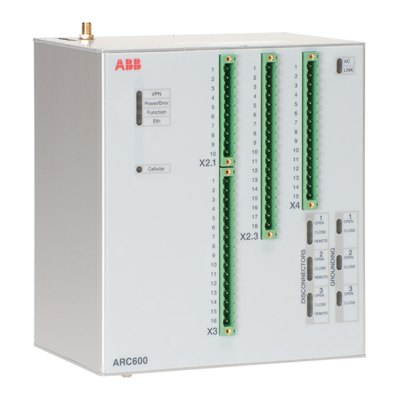
1MRS758459 J ARC600 overview Physical interfaces 2.2.1 Front panel Figure 3: Front panel System status LEDs X2.1 connector X2.3 connector X4 connector AC and LINK LEDs X3 connector Disconnector status LEDs Grounding disconnector status LEDs ARC600 User Manual... -
Page 18: Serial Panel
ARC600 overview 1MRS758459 J 2.2.2 Serial panel Figure 4: Serial panel Console serial port (DIP switch selectable application or console port RS1) Power switch Serial console switch (RS1) Serial port 2 hardware configuration DIP switches Serial port 2 Ethernet connector Protective earth screw 2.2.3... -
Page 19: System Status Leds
1MRS758459 J ARC600 overview SIM card tray connector SIM card tray release button Antenna connector SMA (female) 2.2.4 System status LEDs The device has eight LEDs indicating the system status. They are located on the front panel. Table 1: Description of available LEDs... -
Page 20: Din Rail Mounting
The product label is found on top of the device. Firmware version The device's firmware version is visible on the welcome page (System > Welcome Page), which is displayed after logging in to the device. For firmware updates, contact ABB's technical customer support. ARC600 User Manual... -
Page 21: Physical Connections
The baud rate is fixed to 115200 bps when the port is configured in the serial console mode. Figure 6: Console/RS1 port connector Table 2: Console/RS1 port pinout Function Table continues on the next page ARC600 User Manual... - Page 22 Serial port 2 Serial port 2 can be configured to multiple serial formats (RS-232/422/485). The default is RS-232. Figure 7: Application serial port Table 4: Application serial port pinout (RS-232) Function Table continues on the next page ARC600 User Manual...
- Page 23 Do not connect RS-422 or RS-485 cables to a serial port configured to the RS-232 mode. This could damage the port and the connected equipment. Table 7: Application serial port pinouts in RS-422/485 modes RS-422 full-duplex (4-wire) RS-485 half-duplex (2-wire) RXD positive (in) Table continues on the next page ARC600 User Manual...
-
Page 24: Ethernet
The practical data transfer rates depend on the subscription details and wireless network capacity. The device with wireless interface includes an SMA female type connector for an external antenna. Any kind of external 50 Ω wide band antenna can be used intended ARC600 User Manual... -
Page 25: I/O Connections
Commercially available antennas are usually provided with a flexible 50 Ω cable with a length of 2...3 meters and a male type SMA connector. If the PIN code query is enabled, check that the ARC600 configurator has the correct PIN code entered in the wireless WAN submenu. - Page 26 MSTBV 2,5 HC/10–GF-5,08 (1924606) Matching plug Phoenix Contact MSTB 2,5 HC/10–STF-5,08 (1912265) AC STATUS NTC_A NTC_B 24VDC Figure 9: X2.1 connector schematics With DC (85...200 V DC), connect the negative wire to L and the positive to N. ARC600 User Manual...
-
Page 27: X2.3 Connector
DO1_B Relay output 1 DO2_A Relay output 2 Open disconnector 1 DO2_B Relay output 2 DO3_A Relay output 3 Close disconnector 2 DO3_B Relay output 3 DO4_A Relay output 4 Open disconnector 2 DO4_B Relay output 4 ARC600 User Manual... -
Page 28: X3 Connector
Local/Remote switch for disconnector 3 DI9_B Digital input 9 DO5_A Relay output 5 Close disconnector 3 DO5_B Relay output 5 DO6_A Relay output 6 DO6_B Relay output 6 Open disconnector 3 Table continues on the next page ARC600 User Manual... - Page 29 Panel header Phoenix Contact MSTBV 2,5/16–GF-5,08 (1777219) Matching plug Phoenix Contact MSTB 2,5/16–STF-5,08 (1778124) DISCONNECTOR 3 STATUS & CONTROL GROUNDING DISCONNECTORS STATUS OPENED 3 CLOSED 3 LOC/REM 3 CLOSE 3 OPEN 3 Figure 11: X3 connector schematics ARC600 User Manual...
-
Page 30: X4 Connector
(-10...+55°C, 0 V...+5 V), Hall- sensor DIC_5 Common supply voltage for DI16, DI17 DI16 Digital input 16 DI17 Digital input 17 DO7_A Relay output 7 DO7_B Relay output 7 Can be used as a 4...20 mA input using external resistor ARC600 User Manual... -
Page 31: I/O Leds
The IEC control link to SCADA is active 3.2.6.2 Disconnector LEDs The device has nine LEDs to indicate the disconnector status. They are located on the device front panel. Each disconnector has three LEDs, which indicate the status of the disconnector. ARC600 User Manual... - Page 32 Connector X3 digital input on pin 12 is active high Disconnector 2 open Connector X3 digital input on pin 13 is active high Disconnector 2 close Connector X3 digital input on pin 14 is active high Table continues on the next page ARC600 User Manual...
- Page 33 Connector X3 digital input on pin 15 is active high Disconnector 3 close Connector X3 digital input on pin 16 is active high All grounding disconnector digital input pins have connector X3 pin 10 as the common ground pin. ARC600 User Manual...
-
Page 34: Functional Description
The settings define how the disconnector travel time duration (state change from open to close or vice versa) is reported. Travel time is reported in seconds. The alarm signals remain active until the fault condition is acknowledged. ARC600 User Manual... -
Page 35: Disconnector Actuator Motor Overload Protection
The device's intelligent overload protection function, for example, the resetting and adjustment of the current pick-up level, is managed remotely from a utility dispatch center, using a system such as SCADA. The overload ARC600 User Manual... -
Page 36: Monitoring Of The Pressure Of Sf6 Gas
17 Ah. With the 17 Ah battery, the maximum operation time is 48 hours (including safety coefficient) at ambient temperature of +20°C. A low temperature reduces battery capacity and lifetime. ARC600 User Manual... -
Page 37: Heater Control
Hysteresis can be set for both indication functions. The indication can be reported through any available communication protocol supported by the device. ARC600 User Manual... -
Page 38: Temperature Compensation Of Battery Charging Voltage
Hall sensor, additional DC-powered ARC600 devices or the supply for input circuits should not be connected directly to the battery but to the “master” ARC600 24 VDC In/Out pin (X2.1 pin 6). This way, the whole load can be removed at once when the deep-discharge protection is required. - Page 39 Measurement file The device can generate the internal measurement file from the battery capacity averaging_interval_sec and each line testing. The measurement file is written every contains a time stamp, status, battery voltage, discharge current and the charge ARC600 User Manual...
-
Page 40: Measurement Functions
2.2 kΩ NTC thermistor that is connected to pins 3 and 5 of the connector X2.1. The thermistor is located between the batteries. The measurement data of the sensor is not available with protocol communication but it is only used for adjusting the charging voltage. ARC600 User Manual... -
Page 41: Load Limiter
4.6.1 Overload detection settings The overload detection settings are defined on section [LOAD_LIMITER]. The detection is based on the load current measurement by the external Hall sensor connected to X4 pins 3 and 4. ARC600 User Manual... - Page 42 Time deactivation_time_ms activation_time_ms Accumulated Time STATUS Idle Accumulating Idle Figure 16: Load limiter measurements Accumulated Charge > trip_charge activation_current deactivation_current Time activation_time_ms STATUS Overload Idle Accumulating Idle (charge) CONTROL OUTPUT trip_duration_sec Figure 17: Overload caused by charge ARC600 User Manual...
-
Page 43: Remote Enabling And Disabling Of The Load Limiter
[LOAD_LIMITER_STATUS_DPI]. • 0 = Load limiter idle (waiting for the current to exceed the threshold) • 1 = Load limiter disabled (does not monitor load) • 2 = Loading detected, accumulating • 3 = Overload, load disconnected ARC600 User Manual... -
Page 44: Reason For Load Limiter Activity
[DISCONNECTOR_TRAVELTIME_N]. Support for fault indicators The device contains a driver for the ABB RIO600, Horstmann ComPass-B and Kries IKI-50 fault indicators. The driver polls the fault indicator devices using Modbus and converts the values to IEC 60870-5-104. Up to four fault indicators can be connected. -
Page 45: Cyber Security
Use the default policy to drop connections. • Check that the firewall is enabled. • For incoming connections, always filter (drop) all unused ports which may include DNS, L2TP-VPN, SNMP and so on. ARC600 User Manual... - Page 46 • Set unique passwords for each device. • Keep passwords stored in a safe place, for example, Encrypted password management tool. • Check that all unused services are disabled. • If possible, allow IP connections only via VPN. • Back up the configuration. ARC600 User Manual...
-
Page 47: Getting Started
In a Web browser, connect to the device over the HTTPS protocol using the device’s IP address. Example: The default IP address of the device is 10.10.10.10. The corresponding address to enter in the browser is https://10.10.10.10/. Ignore the browser's warning about a self-signed certificate. ARC600 User Manual... -
Page 48: User Interface
The Home Page opens. 6.2.1 User interface ARC600 configurator is a tool which is used to manage the device properties via a user-friendly, Web-based interface. To use the Web configurator, only a computer with an HTML browser and a connection to the device are needed. With the configurator, it is possible to receive status information and set parameters and variables that control which applications and processes are used with the device. -
Page 49: Configuring Mobile Wan
Interface to Mobile WAN or Ethernet WAN, whichever is not selected as the default gateway. If the primary WAN interface comes down, the device automatically switches the default route to the backup WAN interface. Click Submit to save the settings. Restart the device. ARC600 User Manual... -
Page 50: Network Configuration
If the ping does not get an answer within a given time window, it informs the WAN switch logic to try the secondary interface. 7.2.3 Configuring the mobile WAN interface Set Enable to Yes. ARC600 User Manual... -
Page 51: Setting Wan Failover And Backup Routing
• If both the wireless and Ethernet WAN interfaces have to be up all the time, select No. Click Submit to save the settings. Restart the device. Routing parameters The device has multiple configuration options that define routing. ARC600 User Manual... - Page 52 This setting defines tings which interface to use Ethernet WAN for connection. Wireless WAN Ethernet LAN Routing mode None This setting de- fines how the rout- Host ing is configured with OpenVPN. See OpenVPN application Default route note. ARC600 User Manual...
-
Page 53: Configuring The Network Monitor
In the left pane, under System, click Status to view network status information. In the left pane, under Tools, click Modem Info to view the status of the wireless modem. Check if the cellular LED is flashing, indicating network traffic. ARC600 User Manual... -
Page 54: Serial Port Configuration
Because of the transparent communication, any protocols can be used in actual communication between nodes.Serial gateway configuration depends on used protocols. ARC600 User Manual... -
Page 55: Additional System Configuration
• In the “Manual” mode, enter the time and date in the Time and Date fields, respectively. Clicking Copy PC changes the device’s time and date settings to match the connected PC. This requires JavaScript support from the browser. Click Submit to save the settings. ARC600 User Manual... -
Page 56: Restoring Factory Default Settings
Selecting Last Boot allows saving the configuration in use when the device was booted the previous time. Type a name for the profile. Click Submit to save the profile. It is possible to clone, export, and import profiles in the same view. ARC600 User Manual... -
Page 57: Service Configuration
Determines if logging into the device using SSH is No, Yes allowed. The device has internal SSH server, which allows incoming SSH connections when enabled. By default, the SSH service is enabled for LAN connections. Table continues on the next page ARC600 User Manual... - Page 58 Maximum lease time The maximum lease time given to clients (empty:10800) NTP Servers List of NTP servers (comma separated) LPR Servers List of line printer (LPR) servers (comma sepa- rated) WINS Servers List of WINS servers (comma separated) ARC600 User Manual...
- Page 59 Free-text field for the unique name of the Patrol connection Registration password Password needed to register to server with HTTPS protocol. This password should not be entered after registration unless re- reg- istering is necessary. Table continues on the next page ARC600 User Manual...
- Page 60 XML configuration file to the server. Allow remote management Enables remote management by Patrol serv- No, Yes Allow LAN device scan Allows periodical local network scan for ABB No, Yes devices. Currently, the supported device is RIO600. ARC600...
-
Page 61: Iec-104 Application Settings
IEC-101 slave. The selection be- tween RS-232/422/485 is made with physical DIP switches located below the RS2 serial port. Serial port Indicates the serial port to which the settings RS1, RS2 apply. Table continues on the next page ARC600 User Manual... - Page 62 If the set value is ”Yes”, the present connection is terminated and the new connec- tion is accepted. It is recommendable to set this value to “Yes” in normal configurations having only one IEC-104 master. Table continues on the next page ARC600 User Manual...
- Page 63 This defines the time in seconds how long a con- 1...65000 nected IEC-104 link can be in suspended state (STOPD) before the device closes the connec- tion. Using this parameter increases the proba- Table continues on the next page ARC600 User Manual...
- Page 64 IEC-101 link if the test fails. The events are still not polled before the IEC-104 connection is ac- tive. Some IEC-101 slaves require the link to be continuously open in order to operate. Table continues on the next page ARC600 User Manual...
- Page 65 No, Yes time stamps 24-bit. Packet collector The packet collector can be used to collect many IEC-101 messages and events to a single network packet instead of sending every message sepa- Table continues on the next page ARC600 User Manual...
- Page 66 Other settings Write syslog Write syslog defines if the error messages are No, Yes stored to system log file or not. The system log is available by using Web user interface. ARC600 User Manual...
-
Page 67: Modbus Application Settings
ASCII over TCP and Modbus ASCII over UDP network protocols • Generates and filters out gateway exceptions • Makes automatic connection management • Enables multiple server sessions over the network • Offers unlimited amount of masters on the network side ARC600 User Manual... -
Page 68: Modbus Mode
If the slave does not reply during defined timeout or if the reply is corrupted, the device sends “gateway exception message” back to the master if the exception generation is enabled. Otherwise, the reply is returned. Multiple masters can connect simultaneously to the Gateway, which handles the multiplexing between masters. ARC600 User Manual... -
Page 69: Parameter Settings
Defines the number of data bits used in Mod- 5, 6, 7, 8, Auto bus serial communication. The required number depends on how many data bits the connected Modbus equipment supports. Generally Modbus Table continues on the next page ARC600 User Manual... - Page 70 When the slaves are located on the network side, ping or another method should be used to estimate the delay packets spend on net- work. Table continues on the next page ARC600 User Manual...
- Page 71 Enable keepalive Defines if connection testing is performed by No, Yes sending TCP keepalive packets at certain intervals. enabled for TCP network communication. If set to “Yes”, testing the TCP connection with slave is ena- bled. ARC600 User Manual...
-
Page 72: Technical Data
Frequency range 45...65 Hz Input current, 100% load, 230 0.8 A V AC Efficiency, typical (230 V AC, >83% 100% load) Isolation Input/ground 1500 V AC RMS 50 Hz 1 min Input Table continues on the next page ARC600 User Manual... - Page 73 Table 33: Supply for external devices and input circuits (X2.1 pin 6) Description Value Output voltage 21...29 V Output current 1 A continuous, 2.2 A peak Output overvoltage protection level 30.5 V The maximum operating temperature is +40°C at 1 A load on X2.1 pin 6. ARC600 User Manual...
- Page 74 B IEC 60870-5-101 Modbus (RTU) profile for Kries IKI-50 Modbus TCP Modbus RTU TCP/IP Serial gateway - serial port data stream (such as DNP3) Table 36: Supported protocols for I/O controlling Master protocol IEC 60870-5-104 IEC 60870-5-101 ARC600 User Manual...
- Page 75 ±300 mV for tor load current) -10...+55°C, 0 V...+5 V) Table continues on the next page Digital inputs are designed for reading the status of the feeder (open, traveling, closed) and not for detecting short-duration changes. ARC600 User Manual...
- Page 76 RS-232 DTE Male DB-9 connector IEC 60870-5-101 protocol sup- port Full serial and modem signals 300...460 800 bps Data bits: 7 or 8 Stop bits: 1 or 2 Parity: None, Even, Odd Table continues on the next page ARC600 User Manual...
- Page 77 Radiated radiofrequency EN 61000-4-3 (2006-02) electromagnetic field Electrical fast transient (EFT) EN 61000-4-4 (2012-04) Surge EN 61000-4-5 (2005-11) Conducted radiofrequency EN 61000-4-6 (2008-10) electromagnetic field Power frequency magnetic EN 61000-4-8 (2009-09) field Voltage dips EN 61000-4-11 (2004-03) ARC600 User Manual...
- Page 78 Technical data 1MRS758459 J Table 41: RoHS and REACH compliancy Description Reference Directive RoHS directive 2002/95/EC REACH directive 2006/1907/EC ARC600 User Manual...
-
Page 79: Appendix Installation And Mounting Instructions
Examine the delivered products to ensure that they were not damaged during the transport. If any of the items is missing or damaged, inform the nearest ABB office or representative. ABB should be notified immediately if there are any discrepancies in relation to the delivery documents. - Page 80 Appendix Installation and mounting 1MRS758459 J instructions Use a miniature circuit breaker (MCB) to disconnect ARC600 from the supply. The preferred rating for MCB is 16 A. 14.3 Installing the SIM card Standard 3 V SIM cards (2 FF) can be used with the device's IEC 60870-5-104 gateway.
- Page 81 Hypertext markup language HTTPS Hypertext Transfer Protocol Secure Input/output International Electrotechnical Commission IEC 60870-5-101 Companion standard for basic telecontrol tasks IEC 60870-5-104 Network access for IEC 60870-5-101 Internet protocol Local area network Light-emitting diode Miniature circuit breaker ARC600 User Manual...
- Page 82 2. Station monitoring system SNMP Simple Network Management Protocol SNTP Simple Network Time Protocol Transmission Control Protocol TCP/IP Transmission Control Protocol/Internet Protocol Transmit exchange data User datagram protocol VLAN Virtual LAN Virtual Private Network Wide area network ARC600 User Manual...
- Page 83 — ABB Distribution Solutions Digital Substation Products P.O. Box 699 FI-65101 VAASA, Finland Phone +358 10 22 11 www.abb.com/mediumvoltage www.abb.com/relion www.abb.com/substationautomation © Copyright 2023 ABB. All rights reserved.