Table of Contents
Advertisement
Quick Links
DIGITAL VIDEO CAMERA
GR-DVL307
GR-DVL300
GR-DVL107
GR-DVL100
Please visit our Homepage on the World Wide
Web and answer our Consumer Survey
(in English only):
http://www.jvc-victor.co.jp/english/index-e.html
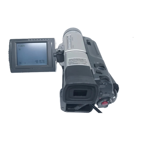
The camcorder illustrations
appearing in this instruction
manual are of the GR-DVL307.
INSTRUCTIONS
CONTENTS
Basic Recording ................................. 12
Advanced Features ............................ 19
Basic Playback .................................. 29
Advanced Features ............................ 30
Basic Connections .............................. 32
Advanced Connections ......................... 34
Dubbing To A VCR ............................. 36
Equipped With A DV Connector ............ 37
With A DV Connector ........................ 38
Playback and Playback Zoom .............. 41
Playback Special Effects ...................... 42
Random Assemble Editing .................... 43
For More Accurate Editing .................... 47
Audio Dubbing .................................. 49
Indications ...................................... 57
Controls, Connectors And Indicators ........ 60
LYT0574-001A
ENGLISH
6 - 11
12 - 28
29 - 35
36 - 38
39 - 49
50 - 56
57 - 61
62
63 - 65
66 - 67
68 - 69
EN
Advertisement
Chapters
Table of Contents

Related Manuals for JVC Mini DV PAL GR-DVL307


Summary of Contents for JVC Mini DV PAL GR-DVL307
-
Page 1: Table Of Contents
Web and answer our Consumer Survey CONTROL UNIT 39 – 49 (in English only): Slow-Motion Playback, Frame-By-Frame http://www.jvc-victor.co.jp/english/index-e.html Playback and Playback Zoom ....41 Playback Special Effects ...... 42 Random Assemble Editing ....43 For More Accurate Editing ....47 Audio Dubbing ........ - Page 2 Dear Customer, Thank you for purchasing this digital video camera. Before use, please read the safety information and precautions contained in the following pages to ensure safe use of this product. Using This Instruction Manual •All major sections and subsections are listed in the Table Of Contents on the cover page. •Notes appear after most subsections.
- Page 3 When the equipment is installed in a cabinet or on a shelf, make sure that it has sufficient space on all sides to allow for ventilation (10 cm or more on both sides, on top and at the rear). Do not block the ventilation holes. (If the ventilation holes are blocked by a newspaper, or cloth etc.
- Page 4 PROVIDED ACCESSORIES •Editing Cable GR-DVL307/DVL300: •Remote One plug has 3 rings around Control Unit •AC Power Adapter/ the pin, and the other has RM-V716U Charger AA-V40EG 1 ring around the pin. GR-DVL107/DVL100: Both plugs have 1 ring around the pin. •AAA (R03) Battery x 2 (for remote control unit)
-
Page 5: Automatic Demonstration
How To Attach The Core Filter Attach the provided Core Filter to an optional S-Video cable or the PC connection cable provided with optional HS-V14KIT software (GR-DVL107/DVL100 only). The Core Filter reduces interference. 3 cm Stopper Wind once Release the Run the cable through the Core Filter, leaving approx. -
Page 6: Getting Started
GETTING STARTED Power This camcorder’s 2-way power supply system lets you To AC outlet Battery pack choose the most appropriate source of power. Do not use BN-V408U, provided power supply units with other equipment. BN-V416U or BN-V428U CHARGING THE BATTERY PACK Make sure you unplug the camcorder’s DC cord from the AC Power Adapter/Charger. - Page 7 USING THE BATTERY PACK Tilt the viewfinder upward BATTERY RELEASE Button With the arrow on the battery pack pointing downward, push the battery pack slightly against the battery pack mount , then slide down the battery pack until it locks in place •If the battery pack is attached with its mark set in the wrong direction, a malfunction may occur.
-
Page 8: Dioptre Adjustment Control
GETTING STARTED (cont.) Grip Adjustment Power Zoom Lever Separate the Velcro strip. Recording Start/Stop button Pass your right hand through the loop and grasp the grip. Adjust so that your thumb and fingers can easily operate the Recording Start/Stop Button and Power Zoom Lever. - Page 9 Date/Time Settings MENU/BRIGHT Wheel The date/time is recorded onto the tape at all times, but its display can be turned on or off during playback pg. 30). Set the Power Switch to “ ” while pressing down the Lock Button located on the switch. The power lamp lights and the camcorder is turned on.
-
Page 10: Open/Eject Switch
GETTING STARTED (cont.) Loading/Unloading A Cassette Erase protection tab* The camcorder needs to be powered up to load or eject a cassette. Make sure the Slide and hold OPEN/EJECT in the direction of the window side is arrow then pull the cassette holder cover open until it facing out. - Page 11 Recording Mode Setting MENU/BRIGHT Wheel Set the tape recording mode depending on your preference. Set the Power Switch to “ ” while pressing down the Lock Button located on the switch. The power lamp lights and the camcorder is turned on. Press MENU/BRIGHT.
-
Page 12: Recording
RECORDING Basic Recording NOTE: Power Switch You should already have performed the procedures listed below. If not, do so before continuing. ● Power ( Lock Button pg. 6) ● Grip Adjustment ( pg. 8) Power lamp ● Viewfinder Adjustment ( pg. - Page 13 Power Switch Position (Manual) : Allows you to set various recording functions using the F . AUTO Menus. If you want more creative capabilities than Full Auto recording, try this mode. (Full Auto) : Allows you to record using NO special effects or manual adjustments.
- Page 14 RECORDING Basic Recording (cont.) Snapshot Power Switch This feature lets you record still images that look like photographs onto a tape. Lock Button SNAPSHOT MODE SELECTION SNAPSHOT Button Set the Power Switch to “ ” or “ ” while pressing down the Lock Button located on the switch.
- Page 15 NOTES: FRAME ● Even if “MULTI-4” or “MULTI-9” is engaged, Snapshot Snapshot mode recording will be performed in the FULL mode during with frame* Digital Zoom. ● If Snapshot recording is not possible, “PHOTO” blinks when SNAPSHOT is pressed. ● If Programme AE with special effects ( pg.
- Page 16 RECORDING Basic Recording (cont.) Zoom in (T: Telephoto) Zooming FEATURE: PURPOSE: 1 xW 1 0 xW To produce the zoom in/out effect, or an instantaneous 20xW 40xW change in image magnification. OPERATION: Zoom In Slide the Power Zoom Lever towards “T”. Zoom out (W: Wide angle) Zoom Out Slide the Power Zoom Lever towards “W”.
- Page 17 NOTE: Recording From The Middle Of A Tape Time Code During recording, a time code is recorded on the tape. This code is to confirm the location of the recorded scene on the tape during playback. If recording starts from a blank portion, the time code begins counting from “00:00:00” (minute:second:frame).
- Page 18 26) is materials. engaged, the light is likely to stay on. It is recommended that you consult your • While the “TWILIGHT” mode ( pg. 26) is nearest JVC dealer for replacing the video engaged, the light will not activate. light.
-
Page 19: Advanced Features
RECORDING Advanced Features While focusing on a further While focusing on a nearer Focus detection zone subject subject Auto Focus FEATURE: PURPOSE: The camcorder’s Full Range AF system offers continuous shooting ability from close-up (as close as approx. 5 cm to the subject) to infinity. However, correct focus may not be obtainable in the situations listed below (in these cases use manual focusing): •When two subjects overlap in the same scene. - Page 20 RECORDING Advanced Features (cont.) Using Menus For Detailed Adjustment Power Switch MENU/BRIGHT Wheel This camcorder is equipped with an easy-to-use, on-screen menu system that simplifies many of the more Lock Button detailed camcorder settings ( pg. 21 – 23). Set the Power Switch to “ ”...
- Page 21 Menu Screen Explanations Refer to “Fade/Wipe Effects” ( pg. 24, 25). FADER/WIPE Refer to “Programme AE With Special Effects” ( pg. 26). P.AE/EFFECT Refer to “Exposure Control” and “Iris Lock” ( pg. 27). EXPOSURE Refer to “White Balance Adjustment” and “Manual White Balance Operation” W.BALANCE pg.
- Page 22 RECORDING Advanced Features (cont.) Menu Screen Explanations (cont.) Demonstrates certain functions such as Programme AE with special effects, DEMO. MODE etc., and can be used to confirm how these functions operate. When “DEMO. MODE” is set to “ON” and the Menu Screen is closed, demonstration starts. Performing any operation during the demonstration stops the demonstration temporarily.
- Page 23 Helps cut down on noise created by wind. “ ” appears. The quality of the WIND sound will change. This is normal. Disengages the function which cuts down on noise created by wind. Does not reset all settings to the factory-preset. CANCEL RESET EXECUTE...
-
Page 24: Stop Button [5]
RECORDING Advanced Features (cont.) Fade/Wipe Effects FADE/WIPE SELECTION ( These effects let you make pro-style scene Fade or Wipe works when recording is started or when transitions. Use them to spice up the transition you stop recording. from one scene to the next. You can also vary transitions from scene to scene. - Page 25 Fader And Wipe Menu Menu Effect Fade in or out with a white screen. FADER — WHITE Fade in or out with a black screen. FADER — BLACK Fade in or out with a full-screen mosaic effect. FADER — MOSAIC Fade in to a colour screen from a black and white screen, or fade out FADER —...
- Page 26 RECORDING Advanced Features (cont.) Programme AE With Special Effects IMPORTANT: Some modes of Programme AE with special effects cannot be used with certain Fade/Wipe Set the Power Switch to “ ” while pressing down Effects ( pg. 25). If an unusable mode is the Lock Button located on the switch.
- Page 27 Exposure Control Iris Lock Use this function in the following situations: Manual exposure adjustment is recommended in the • When shooting a moving subject. following situations: • When the distance to the subject changes (so its • When shooting using reverse lighting or when the size in the LCD monitor or the viewfinder changes), background is too bright.
- Page 28 RECORDING Advanced Features (cont.) White Balance Adjustment Manual White Balance Operation A term that refers to the correctness of colour Perform Manual White Balance when shooting under reproduction under various lighting. If the white various types of lighting. balance is correct, all other colours will be accu- Follow steps 1 through 4 of the white balance rately reproduced.
-
Page 29: Playback
PLAYBACK Basic Playback Play/Pause Button Load a tape ( pg. 10). (4/6) Rewind Button (2) Fast-Forward Button Set the Power Switch to “ ” while pressing down the Lock Button located on the switch. To start playback, press 4/6. Stop Button (5) •To stop playback, press 5. -
Page 30: Advanced Features
PLAYBACK Advanced Features Using Menus For Detailed Adjustment Power Switch The following procedure applies to all except Synchro Comp ( pg. 47, 48). Set the Power Switch to “ ” while pressing down the Lock Button located on the switch. Lock Button Press MENU/BRIGHT. - Page 31 Playback Sound During playback, the camcorder detects the sound mode in which the recording was made, and plays the sound back. Select the type of sound to accompany your playback picture. According to the menu access explanation on pg. 30, select “SOUND MODE” or “12BIT MODE” from the Menu Screen and set it to the desired parameter.
-
Page 32: Basic Connections
PLAYBACK Basic Connections These are some basic types of connections. When making the connections, refer also to your VCR and TV instruction manuals. A. Connection to a TV or VCR equipped with a SCART connector compatible only with regular video signal To TV or VCR To AV... - Page 33 C. Connection to a TV or VCR equipped with an S-VIDEO IN and/or A/V input (RCA type) connectors * When connecting the cables, open this cover. When the S-Video cable is not used. Yellow to VIDEO IN Audio/Video cable [mini-plug to RCA plug] (provided) White to AUDIO L IN Core filter...
-
Page 34: Advanced Connections
PLAYBACK Advanced Connections Connection To A Personal Computer This camcorder can transfer still images to a PC by using the image transfer software (GR-DVL307/DVL300: provided, GR-DVL107/DVL100: optional software such as the HS-V14KIT) when connected as shown in the illustration. It is also possible to transfer still images to a PC with a DV connector-equipped capture board installed. - Page 35 To PC ● Also refer to the instruction manuals of the connected connector units. For GR-DVL300/DVL100 Owners: Core filter When using a DV cable, be sure to use the optional JVC Digital Printer VC-VDV204U DV cable. connection cable*** To RS-232C GR-DVL307/DVL107 only.
-
Page 36: Dubbing
DUBBING Dubbing To A VCR Following the illustration, connect the camcorder and the VCR. Also refer to pg. 32 and 33. Set the camcorder’s Power Switch to “ ” while pressing down the Lock Button located on the switch, turn on the VCR’s power, and insert the appropriate cassettes in the camcorder and the VCR. -
Page 37: Dubbing To A Video Unit Equipped With A Dv Connector
● It is recommended to use the AC Power Adapter/ Charger as the power supply instead of the battery pack pg. 7). ● If the remote control is used when both the player and recorder are JVC video units, both units will perform the same operation. To prevent this from happening, press the buttons on both units. -
Page 38: Dubbing From A Video Unit Equipped With A Dv Connector
● It is recommended to use the AC Power Adapter/Charger as the power supply instead of the battery pack pg. 7). ● If the remote control is used when both the player and recorder are JVC video units, both units will perform the same operation. To prevent this from happening, press the buttons on both units. -
Page 39: Using The Remote Control Unit
USING THE REMOTE CONTROL UNIT The Full-Function Remote Control Unit can operate this camcorder from a distance as well as the basic operations (Playback, Stop, Pause, Fast-Forward and Rewind) of your VCR. It also makes additional playback functions possible. Installing The Batteries The remote control uses two “AAA (R03)”... - Page 40 USING THE REMOTE CONTROL UNIT (cont.) & Functions With the camcorder’s Power With the camcorder’s Power Switch Buttons Switch set to the camera position set to “ ”. (“ ” or “ ”) . Infrared beam transmitting window Transmits the beam signal. Zoom (T/W) Buttons Zoom in/out ( pg.
-
Page 41: Slow-Motion Playback, Frame-By-Frame Playback And Playback Zoom
Remote sensor Slow-Motion Playback FEATURE: PURPOSE: To allow slow-speed search in either direction during playback. OPERATION: 1) To change from normal to Slow-Motion Playback, press PAUSE (6) to engage Still Playback then press SLOW (9 or 0) more than approx. 2 seconds. After approx. -
Page 42: Playback Special Effects
USING THE REMOTE CONTROL UNIT (cont.) BACK PLAYBACK Playback Special Effects FEATURE: EFFECT Select Menu PURPOSE: To allow you to add creative effects to the playback image. OPERATION: 1) To start playback, press PLAY 2) Point the remote control at the camcorder's remote sensor and press EFFECT. -
Page 43: Random Assemble Editing
NAME (A) (B) IMPORTANT AKAI PHILIPS Although the MBR is compatible with JVC VCRs and those of many other makers, it may not work with yours or may offer limited functions. BLAUPUNKT NOTES: ● If the VCR’s power does not come on in step 1, try FERGUSON another code from the VCR CODE LIST. - Page 44 USING THE REMOTE CONTROL UNIT (cont.) MAKE CONNECTIONS Also refer to pg. 32 and 33. A JVC VCR equipped with a remote pause connector ..connect the editing cable to the Remote PAUSE connector. A JVC VCR not equipped with a remote pause connector but equipped with an R.A.EDIT connector .
- Page 45 SELECT SCENES Programme Point the remote control at the camcorder’s remote MODE Random Assemble – – – – – – sensor. Press PLAY (4) and then press R.A.EDIT ON/ Editing Menu OFF on the remote control. The Random Assemble Editing Menu appears. If using a Fade/Wipe at the beginning of the scene, press FADE/WIPE on the remote control.
- Page 46 USING THE REMOTE CONTROL UNIT (cont.) AUTOMATIC EDITING TO VCR Rewind the tape in the camcorder to the beginning of the scene you want to edit and press PAUSE (6). Point the remote control towards the VCR’s remote sensor and press VCR REC STBY (q6), or manually engage the VCR’s Record-Pause mode.
-
Page 47: For More Accurate Editing
For More Accurate Editing Programme 1 Some VCRs make the transition from Record-Pause to MODE Random Assemble Record mode faster than others. Even if you begin editing – – – – – – Editing Menu for the camcorder and the VCR at exactly the same time, you may lose scenes you wanted, or find that you have recorded scenes you did not want. - Page 48 USING THE REMOTE CONTROL UNIT (cont.) ADJUSTMENT OF VCR/CAMCORDER MENU/BRIGHT Wheel TIMING Point the remote control at the camcorder’s remote sensor and press R.A.EDIT ON/OFF to make the Random Assemble Editing menu disappear, then press MENU/BRIGHT. The Menu Screen appears. Rotate MENU/BRIGHT to select “...
-
Page 49: Audio Dubbing
Audio Dubbing Display Audio Dub The audio track can be customized only when recorded in Standby mode the 12-bit mode ( pg. 21). NOTES: ● Audio Dubbing is not possible on a tape recorded in 16-bit audio, on a tape recorded in the LP mode or on a blank portion of a tape. -
Page 50: Troubleshooting
TROUBLESHOOTING If, after following the steps in the chart below, the problem still exists, please consult your nearest JVC dealer. The camcorder is a microcomputer-controlled device. External noise and interference (from a TV, a radio, etc.) might prevent it from functioning properly. In such cases, first disconnect its power supply unit (battery pack, AC Power Adapter/Battery Charger, etc.) and wait a few minutes;... -
Page 51: Backlight Button
SYMPTOM POSSIBLE CAUSES CORRECTIVE ACTION 8. Snapshot mode cannot be 8. •The Squeeze mode is 8. •Disengage the Squeeze used. selected. mode ( pg. 22). 9. The colour of Snapshot 9. •The light source or the 9. •Find a white subject and looks strange. - Page 52 TROUBLESHOOTING (cont.) SYMPTOM POSSIBLE CAUSES CORRECTIVE ACTION 15. The Picture Wipe and 15. •The last selected editing 15. •Select Picture Wipe or Dissolve functions do not scene is ending. Dissolve before beginning work. •At the end of the last recording. The effects are selected scene for editing, then automatically activated the Power Switch was set to...
- Page 53 SYMPTOM POSSIBLE CAUSES CORRECTIVE ACTION 19. Even when Slow Shutter is 19 •When shooting in the dark, 19. •If you want the lighting to not selected, the image the unit becomes highly look more natural, set GAIN looks like it is activated. sensitive to light and the UP to “AGC”...
- Page 54 LCD monitor become dark. Consult your nearest JVC dealer. 27. The rear of the LCD 27. •The light used to illuminate 27. •Close the LCD monitor to monitor is hot.
- Page 55 SYMPTOM POSSIBLE CAUSES CORRECTIVE ACTION 31. During recording, sound 31. •This is normal. ———— cannot be heard. 32. Play, Rewind and Fast- 32. •The Power Switch is not set 32. •Set the Power Switch to Forward functions do not to “ ”.
- Page 56 If the indication remains even though you repeat the above two or three times, please consult your nearest JVC dealer. 40. The charger indicator on 40. •The temperature of the 40. •To protect the battery, it is the AC Power Adapter/...
-
Page 57: Index
INDEX Indications LCD Monitor/Viewfinder Indications During Recording 3 * 4 * & HT – * • BRIGHT : Displays the brightness of the LCD Displays the selected Fade/Wipe effect. pg. 24, 25) monitor. pg. 12) • SOUND : Displays the sound mode for Appears when in the Squeeze or Cinema mode. - Page 58 INDEX Indications (cont.) LCD Monitor/Viewfinder Indications During Playback Displays the sound mode. pg. 30, 31) Displays the tape speed. pg. 11) Appears while a tape is running. : Playback : Fast-Forward/Shuttle search : Rewind/Shuttle search : Pause : Forward slow-motion : Reverse slow-motion : Audio Dubbing : Audio Dubbing Pause...
- Page 59 ● Appears when the built-in clock battery runs out and the SET DATE/TIME! previously set date/time is erased. Consult your nearest JVC dealer for replacement. Appears for 5 seconds after power is turned on if the lens cap is attached.
-
Page 60: Controls, Connectors And Indicators
INDEX Controls, Connectors And Indicators 3 4 5 6 7 8 ^ & * (... -
Page 61: Focus Button
Controls The connectors are located beneath a cover. Audio/Video Output Connector Monitor Open Button [PUSH OPEN] ... pg. 12 [AV] ........pg. 32, 36, 44 Dioptre Adjustment Control ....pg. 8 Digital Video Connector Battery Release Button [DV IN/OUT: GR-DVL307/DVL107, [BATTERY RELEASE] ...... -
Page 62: User Maintenance
USER MAINTENANCE After Use Cleaning The Camcorder Turn off the camcorder. To clean the exterior, wipe gently with a soft cloth. Put the cloth in diluted mild soap and wring it Slide and hold OPEN/EJECT in the direction of well to wipe off heavy dirt. Then wipe again the arrow, then pull the cassette holder cover with a dry cloth. -
Page 63: Cautions
..do not modify or disassemble. It is recommended that you consult your nearest ..do not expose the battery to temperatures JVC dealer for replacing the video light. exceeding 60°C, as this may cause the battery to overheat, explode or catch fire. -
Page 64: Lcd Monitor
If, after using the cleaning cassette, the problems ..allow inflammables, water or metallic objects still exist, consult your nearest JVC dealer. to enter the unit. Mechanical moving parts used to move the video ..remove the battery pack or disconnect the heads and video tape tend to become dirty and power supply while the power is on. - Page 65 If malfunctioning occurs, stop using the unit •Take care not to soil or scratch the mirror surface immediately and consult your local JVC dealer. (opposite to the printed surface). Do not write anything or put a sticker on either the front or back surface.
-
Page 66: Terms
TERMS AC Power Adapter/Charger ..... pg. 6, 7 Fade-In/Out ........pg. 24, 25 Audio Dubbing ........pg. 49 Fast-Forward The Tape ......pg. 29 Auto Focus ..........pg. 19 Frame-By-Frame Playback ....pg. 29, 41 Auto Shut off ........pg. 13, 29 Gain Up ........... - Page 67 Picture Wipe/Dissolve ......pg. 24, 25 Tally ........... pg. 12, 21 Playback Special Effects ......pg. 42 Tele Macro ..........pg. 22 Playback Zoom ........pg. 41 Time Code ......pg. 17, 23, 30, 31 Power Switch Position ......pg. 13 Tripod Mounting .........
-
Page 68: Specifications
SPECIFICATIONS Camcorder For General Power supply : DC 6.3 V (Using AC Power Adapter/Charger) DC 7.2 V (Using battery pack) Power consumption LCD monitor off, viewfinder on : Approx. 4.3 W LCD monitor on, viewfinder off : Approx. 5.3 W Video light : Approx. - Page 69 For Connectors , 75 Ω, analogue output : Y : 1 V , 75 Ω, analogue output C : 0.29 V , 75 Ω, analogue Video output : 1 V Audio output : 300 mV (rms), 1 kΩ, analogue, stereo Input/output (GR-DVL307/DVL107 only) : 4-pin, IEEE 1394 compliant...
- Page 70 MEMO...
- Page 71 MEMO...
- Page 72 VICTOR COMPANY OF JAPAN, LIMITED Printed in Japan COPYRIGHT© 2000 VICTOR COMPANY OF JAPAN, LTD. 0300HOV...