Table of Contents
Advertisement
Quick Links
Advertisement
Table of Contents

Related Manuals for Toro 30327


Summary of Contents for Toro 30327
- Page 1 Form No. 3354-442 Rev A Mid-Size, T-bar, Gear, 15hp or 17hp with 44in Side Discharge Mower Model No. 30326—Serial No. 260000001 and Up Model No. 30327—Serial No. 260000001 and Up Register your product at www.Toro.com Original Instructions (EN)
-
Page 2: Table Of Contents
Whenever you need service, genuine Toro parts, general information worthy of special attention. or additional information, contact an Authorized Service Dealer or Toro Customer Service and have Contents the model and serial numbers of your product ready. Figure 1 identifies the location of the model and serial numbers on the product. - Page 3 1 Removing the Shipping Replacing the Fuel Filter ....33 Bracket and Shipping Electrical System Maintenance....33 Washers......12 Servicing the Fuse ......33 2 Installing the Handle Drive System Maintenance......34 Assembly ......12 Checking the Tire Pressure....34 3 Installing the Fuel Tank ....
-
Page 4: Safety
Safety • Use extra care when handling gasoline and other fuels. They are flammable and vapors are explosive. Note: The addition of attachments made by other manufacturers that do not meet American – Use only an approved container National Standards Institute certification will cause –... -
Page 5: Toro Mower Safety
Stop blades The following list contains safety information if not mowing. specific to Toro products and other safety information you must know. • Be aware of the mower discharge direction and do not point it at anyone. - Page 6 turn over if a wheel goes over the edge of a cliff or ditch, or if an edge caves in. • Use extra care with grass catchers or other attachments. These can change the stability of the machine. • Keep all movement on slopes slow and gradual. Do not make sudden changes in speed or direction.
-
Page 7: Slope Chart
Slope Chart... -
Page 8: Safety And Instructional Decals
Safety and Instructional Decals Safety decals and instructions are easily visible to the operator and are located near any area of potential danger. Replace any decal that is damaged or lost. 66-1340 43-8480 67-5360 68-8340 REVERSE TRACTION DRIVE 82-2280 82-2280 52-2010 82-2290... - Page 9 104-8186 93-1122 95-2814 106-0699 98-0776 98-3256 98-4387 1. Warning—wear hearing protection. 106-5505...
- Page 10 106-5532 105-0884 106-0635 106-5499...
-
Page 11: Setup
Setup Loose Parts Use the chart below to verify that all parts have been shipped. Step Description Qty. Remove the shipping bracket and – No parts required shipping washers. Handle assembly Flanged bolt, (3/8 x 1 inch) Install the handle assembly. Flange nut, (3/8 inch) Fuel tank with studs installed Bolt, (5/16 x 7/8 inch) -
Page 12: Removing The Shipping
Step Removing the Shipping Bracket and Shipping Washers Figure 4 No Parts Required 1. Center Gage Wheels and 4. Washer Spacer 2. Nut 5. Spacer Procedure 3. Bolt 1. Remove the center gage wheel nut, 2 large washers, angle bracket and 1 small washer Step (Figure 3). -
Page 13: Installing The Fuel Tank
Note: Tighten left side of the fuel tank until it is completely tight and then unscrew locknut one full turn. This will allow the spring to work. Figure 5 1. Upper handle 5. Upper mounting hole 2. Rear frame 6. Lower mounting holes 3. -
Page 14: Checking And Adjusting The Shift
Step Checking and Adjusting the Shift Lever Plate No Parts Required Procedure 1. Shift lever to second gear and check alignment of lever in slot of shift lever plate. The clearance between top and bottom of the shift lever should be equal (Figure 8). Figure 9 1. -
Page 15: And Spacers
Note: The upper control bar and fixed bar must be parallel when the upper control bar is in the engaged, drive, neutral, or brake positions. 5. Check the operation. If adjustment is required, remove hairpin cotter, washer and clevis pin securing control rod fitting to idler bracket. -
Page 16: Installing The Hairpin Cotter Pins
• View the safety video. Figure 13 • Fill out the registration card and mail it in or 1. Hairpin cotter 3. Height-of-cut post (rear register online at www.Toro.com. shown) 2. Spacer • Use the oil drain hose when changing the engine oil. -
Page 17: Product Overview
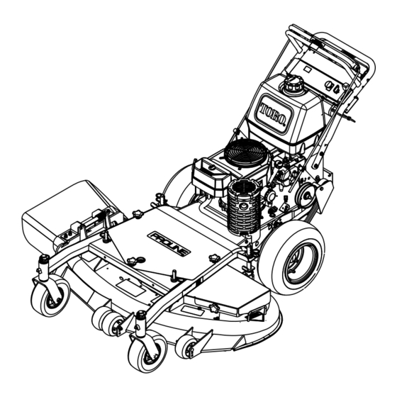
Product Overview Figure 15 1. Side discharge chute 5. Controls 2. Mower deck 6. Handle 3. Recoil starter 7. Caster wheel 4. Gas tank Figure 16 1. Power take off switch (PTO) 7. Lower control bar 2. Parking brake 8. Ignition switch lever-released position Controls 3. - Page 18 Important: Do not shift while unit is moving, as transmission damage may occur. Upper Control Bar Shift to the desired gear and push forward on the upper control bar to engage forward traction operation and pull back to brake forward movement.
-
Page 19: Operation
Operation Recommended Gasoline In certain conditions, gasoline is extremely flammable and highly explosive. A fire or explosion from gasoline can burn you and Use UNLEADED Regular Gasoline suitable others and can damage property. for automotive use (85 pump octane minimum). Leaded regular gasoline may be used if unleaded •... -
Page 20: Checking The Engine Oil Level
to Checking Oil Level in Engine Maintenance, page 28 Gasoline is harmful or fatal if swallowed. Note: Determine the left and right sides of the Long-term exposure to vapors can cause machine from the normal operating position. serious injury and illness. Think Safety First •... -
Page 21: Starting And Stopping The Engine
2. Let engine idle for 30 to 60 seconds before turning the ignition key to off. 3. Turn the ignition key to off (Figure 19). Figure 18 1. Upper control bar 3. Fixed bar 2. Parking brake lever-set position Figure 19 1. -
Page 22: The Safety Interlock System
Testing the Safety Interlock System Test the safety interlock system before you use the machine each time. Note: If the safety system does not operate as described below, have an Authorized Service Dealer repair the safety system immediately. 1. Set the parking brake and start the engine; refer to Starting and Stopping the Engine in Operation, page 19. -
Page 23: Using The Lower Control Bar
4. Lift the front of the machine by pushing down on the lower handle (Figure 22). 5. Drive the machine until drive wheels contact the curb (Figure 22). 6. Lower the front of the machine (Figure 22). Note: Both drive wheels should contact the curb and caster wheels straight. -
Page 24: Stopping The Machine
Note: Lifting up on the lower handle will assist driving the machine up a curb and not spin the drive wheels. Without the grass deflector, discharge cover, or complete grass catcher assembly Stopping the Machine mounted in place, you and others are exposed to blade contact and thrown debris. -
Page 25: Adjusting The Gage Wheels
Figure 24 1. Gage Wheels 4. Washer 2. Nut 5. Spacer 3. Bolt Figure 23 1. Carrier Frame 4. Spacers 2. Hairpin Cotter 5. Back height-of-cut post 3. Front height-of-cut post Adjusting the Gage Wheels The gage wheels need to be adjusted in the proper hole location for each height-of-cut position. - Page 26 and hairpin cotter. Refer to Installing the Control Rods in Setup, page 11. 6. Check the parking brake adjustment. Refer to Checking the Brakes in Brake Maintenance, page 36. Figure 26 1. Control rod and tting 4. Washer 2. Idler bracket 5.
-
Page 27: Maintenance
Maintenance Note: Determine the left and right sides of the machine from the normal operating position. Recommended Maintenance Schedule(s) Maintenance Service Maintenance Procedure Interval After the rst 8 operating • Change the engine oil. hours • Check the safety interlock system. •... -
Page 28: Lubricating The Caster And Wheel
2. Stop the engine, remove the key, and wait for all moving parts to stop before leaving the operating position. 3. Clean the grease fittings with a rag. Make sure to scrape any paint off the front of the fitting(s). 4. - Page 29 Paper element: Check it after every 50 operating hours. Replace it after every 200 operating hours or yearly, which ever comes first. Inspect the foam and paper elements and replace them if they are damaged or excessively dirty. Note: Service the air cleaner more frequently (every few operating hours) if the operating conditions are extremely dusty or sandy.
-
Page 30: Servicing The Engine Oil
Installing the Foam and Paper 3. Stop the engine, remove the key, and wait for Elements all moving parts to stop before leaving the operating position. Important: To prevent engine damage, 4. Clean around the oil dipstick (Figure 33) so always operate the engine with the complete that dirt cannot fall into the filler hole and foam and paper air cleaner assembly installed. -
Page 31: Servicing The Spark Plugs
7. When oil has drained completely, close the drain valve. 8. Remove the drain hose (Figure 34). Note: Dispose of the used oil at a recycling center. Figure 35 1. Oil lter 2. Adapter 3. Apply a thin coat of new oil to the rubber gasket on the replacement filter (Figure 35). -
Page 32: Fuel System Maintenance
Important: Always replace the spark plugs when it has a black coating, worn electrodes, an oily film, or cracks. 3. Check the gap between the center and side electrodes (Figure 37). Bend the side electrode (Figure 37) if the gap is not correct. Installing the Spark Plugs 1. -
Page 33: Replacing The Fuel Filter
Note: Now is the best time to install a new fuel filter because the fuel tank is empty. Refer to Replacing the Fuel Filter. 5. Install the fuel line onto the fuel filter. Slide the hose clamp close to the valve to secure the fuel line. -
Page 34: Drive System Maintenance
Replacing the Caster Wheel Fork Bushings The caster wheel forks are mounted in bushings pressed into the top and bottom of the carrier frame mounting tubes. To check the bushings, move the caster forks back and forth and side-to-side. If a caster fork is loose, the bushings are worn and must be replaced. -
Page 35: Servicing The Caster Wheel And Bearings
Figure 43 1. Mounting Tube 2. Bushing Figure 44 5. Grease the inside and outside of the new 1. Locknut 4. Spanner Bushing 2. Wheel Bolt 5. Roller Bearing bushings. Use a hammer and flat plate to 3. Bushing carefully drive the bushings into the mounting tube. -
Page 36: Cooling System Maintenance
brake does not hold securely, an adjustment is required. Checking the Brakes 1. Park the machine on a level surface, disengage the PTO. 2. Stop the engine, remove the key, and wait for all moving parts to stop before leaving the operating position. -
Page 37: Belt Maintenance
1. Remove the top capscrew securing idler support and idler bracket to rear frame (Figure 47). Figure 47 Figure 46 1. Top capscrew 4. Bottom capscrew 1. Hairpin cotter and washer 5. Hole F 2. Idler bracket 5. Traction drive belt 2. -
Page 38: Replacing The Mower Belt
5. Disconnect clutch wire connector from wire 4. Remove the knobs/rubber washers holding harness. the belt cover to the cutting unit and remove the belt cover. 6. Disconnect clutch retainer from the engine 5. Remove the PTO drive belt. Refer to Replacing deck (Figure 48). -
Page 39: Mower Deck Maintenance
1. Disengage the PTO and set the parking brake. 2. Stop the engine, remove the key, and wait for all moving parts to stop before leaving the operating position. 3. Remove the knobs/rubber washers holding the carrier frame cover and remove the carrier frame cover. - Page 40 To ensure optimum performance and continued safety conformance of the machine, use genuine Toro replacement blades. Replacement blades made by other manufacturers may result in non-conformance with safety standards. 1. Hold the blade end using a rag or thickly-padded glove.
-
Page 41: Correcting The Mower Quality Of
To ensure optimum performance and continued safety conformance of the machine, use genuine Toro replacement blades. Replacement blades made by other manufacturers may result in non-conformance with safety standards. Figure 54 1. -
Page 42: Adjusting The Frame
operating position. Disconnect the spark plug 7. Align the carrier frame and engine deck to wire(s) from the spark plug(s). match 1-5/16 inch (33 mm), plus or minus a 1/4 inch (6 mm) at location A (Figure 56). 3. Adjust the tire pressure in all tires to specifications on page . -
Page 43: Checking The Mower Deck
Figure 59 Figure 58 4. Same height at locations A 1. Caster Wheel 1. Caster Wheel 4. Height at locations A and B and B 2. Carrier Frame 5. Caster spacers 2. Carrier Frame 5. Caster spacers 3. 1/4-3/8 inch (6-10 mm) 3. -
Page 44: Changing The Deck Front-To-Rear Pitch
3. To lower the front of the deck, loosen jam nut and rotate the front pin counter clockwise (Figure 61). 4. Position the blades front-to-rear. Measure at C and D locations (Figure 60) from a level surface to the cutting edge of the blades. 5. -
Page 45: Matching Height Of Cut
Replacing the Grass 1. Change the tire pressure on both deck and Deector traction unit. Do this to the corresponding side that needs adjustment. 2. Recheck the front-to-rear pitch and side to side leveling of the cutting unit. An uncovered discharge opening could allow the lawn mower to throw objects in Matching Height of Cut the operator’s or bystander’s direction and... - Page 46 Note: Make sure the L end of spring is installed behind deck edge before installing the bolt as shown in Figure 64. 3. Install bolt and nut. Place the J hook end of spring around grass deflector (Figure 64). Important: The grass deflector must be able to rotate.
-
Page 47: Storage
Storage Engine Maintenance, page 28. With the spark plug(s) removed from the engine, pour two tablespoons of engine oil into the spark plug Cleaning and Storage hole. Now use the starter to crank the engine and distribute the oil inside the cylinder. Install 1. -
Page 48: Troubleshooting
Troubleshooting Problem Possible Cause Corrective Action Engine will not start, starts 1. Fuel tank is empty. 1. Fill fuel tank with hard, or fails to keep gasoline. running. 2. Choke is not on. 2. Move the throttle lever to choke position. 3. - Page 49 Problem Possible Cause Corrective Action Machine does not drive. 1. Shift lever is in neutral. 1. Move shift lever to a drive gear position. 2. Traction belt is worn, 2. Change the belt. loose or broken. 3. Traction belt is off a 3.
- Page 50 Problem Possible Cause Corrective Action Blades do not rotate. 1. Drive belt is worn, loose 1. Check the belt tension. or broken. 2. Drive belt is off pulley. 2. Install drive belt and check adjusting shafts and belt guides for correct position.
-
Page 51: Schematics
Schematics Electrical Schematic (Rev. A) - Page 55 The use of any add-on or modied parts will be grounds for disallowing a warranty claim made in accordance with this article. The Toro® Company will not be liable under this Article to warrant failures of warranted parts caused by the use of an add-on or modied part.
- Page 56 (Dealer) to obtain guarantee policies for your country, province, or state. If for any reason you are dissatised with your Distributor’s service or have difculty obtaining guarantee information, contact the Toro importer. If all other remedies fail, you may contact us at Toro Warranty Company.