Table of Contents
Advertisement
Quick Links
SIMATIC NET
Industrial Ethernet switches
SCALANCE X-100
Operating Instructions
02/2019
A2B00060666-10
Introduction
Safety notices
Network topologies
Description of the device
Assembly
Connecting up
Maintenance and
troubleshooting
Technical specifications
Dimension drawings
Certifications and approvals
1
2
3
4
5
6
7
8
9
10
Advertisement
Table of Contents

Related Manuals for Siemens SIMATIC NET SCALANCE X-100


Summary of Contents for Siemens SIMATIC NET SCALANCE X-100
- Page 1 Introduction Safety notices Network topologies SIMATIC NET Description of the device Industrial Ethernet switches SCALANCE X-100 Assembly Connecting up Operating Instructions Maintenance and troubleshooting Technical specifications Dimension drawings Certifications and approvals 02/2019 A2B00060666-10...
- Page 2 Note the following: WARNING Siemens products may only be used for the applications described in the catalog and in the relevant technical documentation. If products and components from other manufacturers are used, these must be recommended or approved by Siemens. Proper transport, storage, installation, assembly, commissioning, operation and maintenance are required to ensure that the products operate safely and without any problems.
-
Page 3: Table Of Contents
Table of contents Introduction..............................5 On the Operating Instructions ....................5 Safety notices ...............................9 Network topologies .............................11 Description of the device ..........................13 Purpose..........................13 Product overview........................13 Product properties and device views ..................15 4.3.1 Overview of the SCALANCE X-100 ..................15 4.3.2 SCALANCE X104-2 .......................16 4.3.3 SCALANCE X106-1 .......................17 4.3.4... - Page 4 Table of contents Technical specifications..........................43 SCALANCE X104-2 .......................43 8.1.1 SCALANCE X104-2 .......................43 SCALANCE X106-1 .......................46 8.2.1 SCALANCE X106-1 .......................46 SCALANCE X108 ........................49 SCALANCE X108PoE......................51 SCALANCE X112-2 .......................53 8.5.1 SCALANCE X112-2 .......................53 SCALANCE X116 ........................56 SCALANCE X124 ........................58 Mechanical stability (in operation)..................61 Dimension drawings ...........................63 Certifications and approvals ........................69 Index................................77...
-
Page 5: Introduction
See also SIMATIC NET Industrial TP and FO networks (https://support.automation.siemens.com/WW/ view/en/1172207) https://siemens.com/scalance (https://siemens.com/scalance) Further documentation In the system manuals "Industrial Ethernet / PROFINET Industrial Ethernet" and "Industrial Ethernet / PROFINET passive network components", you will find information on other SIMATIC NET products that you can operate along with the devices of this product line in an Industrial Ethernet network. - Page 6 In order to protect plants, systems, machines and networks against cyber threats, it is necessary to implement – and continuously maintain – a holistic, state-of-the-art industrial security concept. Siemens’ products and solutions constitute one element of such a concept. Customers are responsible for preventing unauthorized access to their plants, systems, machines and networks.
- Page 7 Feed under https://www.siemens.com/industrialsecurity (https://www.siemens.com/industrialsecurity) Catalogs You will find the article numbers for the Siemens products of relevance here in the following catalogs: ● SIMATIC NET Industrial Communication / Industrial Identification, catalog IK PI ● SIMATIC Products for Totally Integrated Automation and Micro Automation, catalog ST 70 ●...
- Page 8 Introduction 1.1 On the Operating Instructions Electrostatic discharge NOTICE Electrostatic sensitive devices (ESD) Electronic modules contain electrostatic sensitive components These components can easily be destroyed if handled incorrectly. Note the following instructions to avoid damage. ● Touch electronic modules only when you absolutely need to work on them. ●...
-
Page 9: Safety Notices
Safety notices Read the safety notices Note the following safety notices. These relate to the entire working life of the device. You should also read the safety notices relating to handling in the individual sections, particularly in the sections "Installation" and "Connecting up". CAUTION To prevent injury, read the manual before use. - Page 10 Safety notices SCALANCE X-100 Operating Instructions, 02/2019, A2B00060666-10...
-
Page 11: Network Topologies
Network topologies Switching technology allows extensive networks to be set up with numerous nodes and simplifies network expansion. Which topologies can be implemented? Using the IE switches of the SCALANCE X-100 product line, you can implement star topologies. Note Keep to the maximum permitted cable lengths of the devices you are using. You will find the permitted cable lengths in the section "Technical specifications (Page 43)". - Page 12 Network topologies Figure 3-1 Example of an electrical star topology with SCALANCE X124 PROFINET Industrial Ethernet Industrial Ethernet (Twisted Pair) Industrial Ethernet (Fiber Optic) Figure 3-2 Example of an electrical/optical star topology with SCALANCE X112-2 and SCALANCE X104-2 SCALANCE X-100 Operating Instructions, 02/2019, A2B00060666-10...
-
Page 13: Description Of The Device
Description of the device Purpose What is possible? The devices of the SCALANCE X100 product line allow the cost-effective installation of Industrial Ethernet bus and star structures with switching functionality. With the following IE switches, there are also electrical/optical media transitions: ●... - Page 14 Description of the device 4.2 Product overview Device Description Article number SCALANCE X112-2 12x 10/100 Mbps RJ45 ports, 2x 100 Mbps 6GK5 112-2BB00-2AA3 multimode BFOC SCALANCE X116 16x 10/100 Mbps RJ45 ports 6GK5 116-0BA00-2AA3 SCALANCE X124 24x 10/100 Mbps RJ45 ports 6GK5 124-0BA00-2AA3 Unpacking and checking WARNING...
-
Page 15: Product Properties And Device Views
Description of the device 4.3 Product properties and device views Component Packaging unit Order number IE FC TP festoon cable GP 6XV1871-2S IE FC TP food cable 6XV1871-2L IE TP torsion cable 6XV1870-2F FO standard cable GP (50/125) 6XV1873-2A FO trailing cable (50/125) 6XV1873-2C FO trailing cable GP (50/125) 6XV1873-2D... -
Page 16: Scalance X104-2
Description of the device 4.3 Product properties and device views Fast learning: Fast recognition of MAC addresses on the device that change during operation (for example, when an end node is reconnected). Table 4-2 Overview of the connection options Device type SCALANCE X104-2 X10⁶-1 X10⁸... -
Page 17: Scalance X106-1
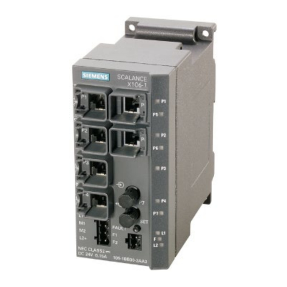
Description of the device 4.3 Product properties and device views 4.3.3 SCALANCE X106-1 Possible connections The SCALANCE X106-1 has six RJ-45 jacks and a BFOC socket for the connection of end devices or other network segments. Note The BFOC socket (Bayonet Fiber Optic Connector) corresponds to the ST socket. Figure 4-2 SCALANCE X106-1 4.3.4... - Page 18 Description of the device 4.3 Product properties and device views Figure 4-3 SCALANCE X108 SCALANCE X-100 Operating Instructions, 02/2019, A2B00060666-10...
-
Page 19: Scalance X108Poe
Description of the device 4.3 Product properties and device views 4.3.5 SCALANCE X108PoE Possible connections The SCALANCE X108 PoE has eight RJ-45 jacks for the connection of end devices or other network segments. Ports 1 and 2 have the PoE function. Figure 4-4 SCALANCE X108PoE Power over Ethernet (PoE) function... -
Page 20: Scalance X112-2
Description of the device 4.3 Product properties and device views 4.3.6 SCALANCE X112-2 Possible connections The SCALANCE X112-2 has twelve RJ-45 jacks and two BFOC sockets for the connection of end devices or other network segments. Note The BFOC socket (Bayonet Fiber Optic Connector) corresponds to the ST socket. Figure 4-5 SCALANCE X112-2 SCALANCE X-100... -
Page 21: Scalance X116
Description of the device 4.3 Product properties and device views 4.3.7 SCALANCE X116 Possible connections The SCALANCE X116 has 16 RJ-45 jacks for the connection of end devices or other network segments. Figure 4-6 SCALANCE X116 SCALANCE X-100 Operating Instructions, 02/2019, A2B00060666-10... -
Page 22: Scalance X124
Description of the device 4.4 TP ports (twisted pair) 4.3.8 SCALANCE X124 Possible connections The SCALANCE X124 has 24 RJ-45 jacks for the connection of end devices or other network segments. Figure 4-7 SCALANCE X124 TP ports (twisted pair) Note Strain relief for the Ethernet cables In order to avoid mechanical stress on the Ethernet cables and resulting interruption of the contact, fasten the cables at a short distance from the connector using a cable guide or busbar. - Page 23 Description of the device 4.4 TP ports (twisted pair) RJ-45 connector pinout With SCALANCE X-100, the twisted-pair port is designed as an RJ-45 jack with MDI-X pin assignment (Medium Dependent Interface Autocrossover) of a network component. Special features of the SCALANCE X108PoE Over and above the pure Ethernet functionality, ports 1 and 2 of the SCALANCE X108PoE can also be used to supply power to Power-over-Ethernet end devices (for example SCALANCE- W) in compliance with 802.3af.
- Page 24 Description of the device 4.4 TP ports (twisted pair) Note Permitted cable lengths TP cords or TP-XP cords with a maximum length of 10 m can be connected to the TP port with the RJ-45 jack. With the IE FC cables and IE FC RJ-45 plugs 180, an overall cable length of a maximum of 100 m is permitted between two devices depending on the cable type.
-
Page 25: Fo Port (Fiber Optic)
Description of the device 4.5 FO port (fiber optic) The IE Switches SCALANCE X-100 all support the MDI / MDI-X autocrossover function. NOTICE Formation of loops Note that the direct connection of two ports or accidental connection over several switches causes an illegal loop that can cause network overload and failure. -
Page 26: Led Display
Description of the device 4.7 SET button LED display Fault LED "F" (red LED) The fault LED indicates the incorrect functioning of the device. LED color LED status Meaning The IE switch detects an error. At the same time, the signaling contact opens. The following faults/errors are detected: 1. - Page 27 Description of the device 4.7 SET button Setting the fault mask Factory setting In its delivery condition (factory default), the following settings are monitored via the message screen: ● Link up to all ports ● Redundant power supply (L1+/M1 und L2+/M2) connected When you turn the device on and at least one of the settings is not fulfilled, the device registers a fault.
- Page 28 Description of the device 4.7 SET button SCALANCE X-100 Operating Instructions, 02/2019, A2B00060666-10...
-
Page 29: Assembly
Assembly Safety notices for installation Safety notices When installing the device, keep to the safety notices listed below. WARNING Ambient temperature above 55 °C If a device is operated in an ambient temperature of more than 55 °C, the temperature of the device housing may be higher than 70 °C. - Page 30 Assembly 5.1 Safety notices for installation Safety notices for use according to ATEX and IECEx If you use the device under ATEX or IECEx conditions you must also keep to the following safety notices in addition to the general safety notices for protection against explosion: WARNING To comply with EC Directive 2014/34/EU (ATEX 114) or the conditions of IECEx, this enclosure or cabinet must meet the requirements of at least IP54 in compliance with EN...
-
Page 31: Types Of Installation
Assembly 5.3 Installation on a DIN rail Types of installation The devices can be installed in the following ways: ● Installation on a 35 mm DIN rail ● Installation on a SIMATIC S7-300 standard rail ● Wall mounting WARNING If a device is operated in an ambient temperature between 50 ℃ and 75 ℃, the temperature of the device housing may be higher than 70 °C. - Page 32 Assembly 5.3 Installation on a DIN rail Figure 5-1 Installation on a 35 mm DIN rail Uninstalling To remove the device from the DIN rail, follow the steps below: 1. Disconnect all connected cables. 2. Release the DIN rail catch on the bottom of the device using a screwdriver. 3.
-
Page 33: Installation On A Standard Rail
Assembly 5.4 Installation on a standard rail Figure 5-2 Removal from a 35 mm DIN rail Installation on a standard rail Installation on a SIMATIC S7-300 standard rail To install the device on an S7-300 standard rail, follow the steps below: 1. -
Page 34: Wall Mounting
Assembly 5.5 Wall mounting 4. Fit the connectors for the signaling contacts. See also section "Signaling contacts (Page 37)". 5. Insert the terminal blocks into the sockets on the device. Figure 5-3 Installation on a SIMATIC S7-300 standard rail Uninstalling To remove the device from the S7-300 standard rail, follow the steps below: 1. -
Page 35: Connecting Up
Connecting up Safety when connecting up Safety notices When connecting up the device, keep to the safety notices listed below. WARNING The equipment is designed for operation with Safety Extra-Low Voltage (SELV) by a Limited Power Source (LPS). This means that only SELV / LPS complying with IEC 60950-1 / EN 60950-1 / VDE 0805-1 must be connected to the power supply terminals, or the power supply unit for the equipment power supply must comply with NEC Class 2, as described by the National Electrical Code (r) (ANSI / NFPA 70). -
Page 36: Power Supply
Connecting up 6.2 Power supply Safety notices on use in hazardous areas General safety notices relating to protection against explosion WARNING EXPLOSION HAZARD Do not connect or disconnect cables to or from the device when a flammable or combustible atmosphere is present. Safety notices when using the device according to Hazardous Locations (HazLoc) If you use the device under HazLoc conditions you must also keep to the following safety notices in addition to the general safety notices for protection against explosion:... -
Page 37: Signaling Contact
Connecting up 6.3 Signaling contact Pin number Assignment Pin 1 L1+ (24 VDC) Pin 2 M1 (ground) Pin 3 M2 (ground) Pin 4 L2+ (24 VDC) WARNING Incorrect power supply The power supply unit to supply the device must comply with NEC Class 2 (voltage range 18 - 32 V, current requirement 350 mA). -
Page 38: Grounding
Connecting up 6.4 Grounding Pin number Assignment Pin 1 Pin 2 The following errors/faults can be signaled by the signaling contact: ● The failure of a link at a monitored port. ● The failure of one of the two monitored power supplies. The connection or disconnection of a communication node on an unmonitored port does not lead to an error message. -
Page 39: Ie Fc Rj-45 Plug 180
Connecting up 6.5 IE FC RJ-45 Plug 180 IE FC RJ-45 Plug 180 The rugged node connectors are designed for industry with PROFINET-compliant connectors and provide additional strain and bending relief with a locking mechanism on the casing. Fitting the IE FC RJ45 Plug 180 to the IE FC Standard Cable You will find the notes on installation in the instructions that ship with the IE FC RJ45 Plug 180. - Page 40 Connecting up 6.5 IE FC RJ-45 Plug 180 Plugging in the IE FC RJ45 Plug 180 Plug the IE FC RJ45 Plug 180 into the twisted-pair port of the device until it locks in place. Figure 6-2 Plugging in the IE FC RJ45 Plug 180 With its tight fit and locking mechanism with the PROFINET-compliant male connector IE FC RJ45 Plug 180, the securing collar on the TP port of the device ensures a rugged node attachment that provides strain and bending relief for the RJ-45 jack.
-
Page 41: Maintenance And Troubleshooting
If both of the power supplies drop below approximately 14 V, this reduced voltage is indicated by the red fault LED. The L LEDs go off. Device defective If a fault develops, please send the device to your SIEMENS service center for repair. Repairs on-site are not possible. SCALANCE X-100... - Page 42 Maintenance and troubleshooting 7.1 Possible sources of problems and how to deal with them SCALANCE X-100 Operating Instructions, 02/2019, A2B00060666-10...
-
Page 43: Technical Specifications
Technical specifications SCALANCE X104-2 8.1.1 SCALANCE X104-2 Table 8-1 Technical specifications of the SCALANCE X104-2 Technical specifications Order number SCALANCE X104-2 6GK5104‑2BB00‑2AA3 Connection to Industrial Ethernet Number Design RJ-45 jacks with MDI‑X pinning Properties Half / full duplex Transmission speed 10/100 Mbps Optical connectors Number... - Page 44 Technical specifications 8.1 SCALANCE X104-2 Technical specifications Electrical data Power supply Voltage range 18 to 32 VDC Safe Extra Low Voltage (SELV) Rated voltage 24 VDC Design 4-terminal plug-in block Signaling contact Current max. 100 mA Rated voltage 24 VDC Design 2-pin plug-in terminal block Current consumption...
- Page 45 Technical specifications 8.1 SCALANCE X104-2 Technical specifications Maximum frame size 1536 bytes Forwarding of PRP frames (Parallel Redundancy Protocol) Note The number of SCALANCE X Industrial Ethernet switches connected in a line influences the frame delay time. When a frame passes through devices of the SCALANCE X-100 product line, it is delayed by the store and forward function of the switch ●...
-
Page 46: Scalance X106-1
Technical specifications 8.2 SCALANCE X106-1 Properties Receiver input Sensitivity min. -32 dBm Input power max. -3 dBm *) Depending on the cable used: ● If you are using at least OM1 fibers (attenuation ≤ 1.5 dB/km, bandwidth length product ≥ 500 MHz*km), you can reach a cable length of up to 3 km. - Page 47 Technical specifications 8.2 SCALANCE X106-1 Technical specifications Optical parameters Cable type Multimode glass FO cable, cable cross sections 62.5/125 μm and 50/125 μm Permitted cable length (glass FO ca‐ Cable cross-section Permitted cable length ble) ● 62.5/125 μm ● 0 to 4000 m ●...
- Page 48 Technical specifications 8.2 SCALANCE X106-1 Technical specifications Aging time 30 seconds Max. number of learnable MAC ad‐ 2048 dresses Response to LLDP frames Blocking Response to spanning tree BPDU Forwarding frames CoS acc. to IEEE 802.1Q QoS priority queues Maximum frame size 1536 bytes Forwarding of PRP frames (Parallel Redundancy Protocol)
-
Page 49: Scalance X108
Technical specifications 8.3 SCALANCE X108 Properties Wavelength 1300 nm Cable length (max.) * At 50 µm fiber core diameter 3 km At 62.5 µm fiber core diameter 3 km Transmitter output (optical) Minimum At 50 μm -23 dBm At 62.5 μm -19 dBm Maximum -14 dBm... - Page 50 Technical specifications 8.3 SCALANCE X108 Technical specifications Power supply Voltage range 18 to 32 VDC Safe Extra Low Voltage (SELV) Rated voltage 24 VDC Design 4-terminal plug-in block Signaling contact Current max. 100 mA Rated voltage 24 VDC Design 2-pin plug-in terminal block Current consumption Typical 140 mA...
-
Page 51: Scalance X108Poe
Technical specifications 8.4 SCALANCE X108PoE Technical specifications Maximum frame size 1536 bytes Forwarding of PRP frames (Parallel Redundancy Protocol) Note The number of SCALANCE X Industrial Ethernet switches connected in a line influences the frame delay time. When a frame passes through devices of the SCALANCE X-100 product line, it is delayed by the store and forward function of the switch ●... - Page 52 Technical specifications 8.4 SCALANCE X108PoE Technical specifications Electrical data Power supply Voltage range 18 to 32 VDC Safe Extra Low Voltage (SELV) Rated voltage 24 VDC Design 4-terminal plug-in block Signaling contact Current max. 100 mA Rated voltage 24 VDC Design 2-pin plug-in terminal block Current consumption...
-
Page 53: Scalance X112-2
Technical specifications 8.5 SCALANCE X112-2 Technical specifications Forwarding of PRP frames (Parallel Redundancy Protocol) PoE properties PoE standard 802.3af Performance maximum 15.4 W Note As of an ambient temperature of 55 °C, there must be a clearance of 40 mm to neighboring devices on both sides. - Page 54 Technical specifications 8.5 SCALANCE X112-2 Technical specifications Optical connectors Number Design BFOC sockets Properties Full duplex to 100 Base-FX Transmission speed 100 Mbps Permitted cable lengths (Industrial Alternative combinations per length range Ethernet) 0 to 55 m ● Max. 55 m IE TP Torsion Cable with IE FC RJ45 Plug 180 ●...
- Page 55 Technical specifications 8.5 SCALANCE X112-2 Technical specifications Immunity to interference EN 61000-6-2 Emission EN 61000-6-3 Degree of protection IP 30 MTBF (EN/IEC 61709, 40 °C) 61.3 years Housing material Basic housing Die cast aluminum, powder coated Front cover Polyphenylene ether + polystyrene (PPE +PS plastic) Weight 1100 g...
-
Page 56: Scalance X116
Technical specifications 8.6 SCALANCE X116 Optical connectors Quantity Connectors The attachment to Industrial Ethernet uses ST/ BFOC connector technology (Straight Tip/Bayo‐ net Fiber Optic Connector). Properties Transmission mode 100Base-FX complying with IEEE 802.3 Transmission rate 100 Mbps (Fast Ethernet) Transmission medium Multimode fiber-optic cable Light source LED/Class1-LASER "Eye safe"... - Page 57 Technical specifications 8.6 SCALANCE X116 Technical specifications Design RJ-45 jacks with MDI‑X pinning Properties Half / full duplex Transmission speed 10/100 Mbps Permitted cable lengths (Industrial Alternative combinations per length range Ethernet) 0 to 55 m ● Max. 55 m IE TP Torsion Cable with IE FC RJ45 Plug 180 ●...
-
Page 58: Scalance X124
Technical specifications 8.7 SCALANCE X124 Technical specifications Installation options ● Installation on a DIN rail ● Installation on an S7-300 standard rail ● Wall mounting Switching properties Aging time 30 seconds Max. number of learnable MAC ad‐ 2048 dresses Response to LLDP frames Blocking Response to spanning tree BPDU Forwarding... - Page 59 Technical specifications 8.7 SCALANCE X124 Technical specifications Design RJ-45 jacks with MDI‑X pinning Properties Half / full duplex Transmission speed 10/100 Mbps Permitted cable lengths (Industrial Alternative combinations per length range Ethernet) 0 to 55 m ● Max. 55 m IE TP Torsion Cable with IE FC RJ45 Plug 180 ●...
- Page 60 Technical specifications 8.7 SCALANCE X124 Technical specifications Installation options ● Installation on a DIN rail ● Installation on an S7-300 standard rail ● Wall mounting Switching properties Aging time 30 seconds Max. number of learnable MAC ad‐ 2048 dresses Response to LLDP frames Blocking Response to spanning tree BPDU Forwarding...
-
Page 61: Mechanical Stability (In Operation)
Technical specifications 8.8 Mechanical stability (in operation) Mechanical stability (in operation) Mechanical stability (in operation) Device DIN EN 60068-2-6 os‐ DIN EN 60068-2-6 os‐ DIN EN 60068-2-6 os‐ DIN EN 60068-2-29 DIN EN 60068-2-29 cillation cillation cillation permanent shock permanent shock 10 - 58 Hz: 0.075 mm 10 - 58 Hz: 0.15 mm 5 - 8.51 Hz: 3.5 mm... - Page 62 Technical specifications 8.8 Mechanical stability (in operation) SCALANCE X-100 Operating Instructions, 02/2019, A2B00060666-10...
-
Page 63: Dimension Drawings
Dimension drawings Figure 9-1 Dimension drawing, rear of the SCALANCE X104-2, X106-1, X108, X108PoE SCALANCE X-100 Operating Instructions, 02/2019, A2B00060666-10... - Page 64 Dimension drawings Figure 9-2 Dimension drawing, rear of the SCALANCE X116, X112-2 SCALANCE X-100 Operating Instructions, 02/2019, A2B00060666-10...
- Page 65 Dimension drawings Figure 9-3 Dimension drawing, rear of the SCALANCE X124 SCALANCE X-100 Operating Instructions, 02/2019, A2B00060666-10...
- Page 66 Dimension drawings Figure 9-4 Dimension drawing, side view SCALANCE X-100 Operating Instructions, 02/2019, A2B00060666-10...
- Page 67 Dimension drawings Figure 9-5 Dimension drawing, bending radii SCALANCE X-100 Operating Instructions, 02/2019, A2B00060666-10...
- Page 68 Dimension drawings SCALANCE X-100 Operating Instructions, 02/2019, A2B00060666-10...
-
Page 69: Certifications And Approvals
Current approvals on the Internet You will find the current approvals for the product on the Internet pages of Siemens Industry Online Support (https://support.industry.siemens.com/cs/ww/en/ps/15273/cert). Notes for the manufacturers of machines The devices are not machines in the sense of the EC Machinery Directive. - Page 70 You will find this document here: ● On the data medium that ships with some products: – Product CD / product DVD – SIMATIC NET Manual Collection ● On the Internet pages of Siemens Industry Online Support (https:// support.industry.siemens.com/cs/ww/en/view/78381013) SCALANCE X-100...
- Page 71 Certifications and approvals The SIMATIC NET products described in these operating instructions meet the requirements of the EU directive 2014/34/EU "Equipment and Protective Devices for Use in Potentially Explosive Atmospheres". Note Type of protection of the device The devices are approved for various types of protection. You can find the type of protection of your device and the ATEX certificate number on the nameplate.
- Page 72 Certifications and approvals IECEx The SIMATIC NET products described in these operating instructions meet the requirements of explosion protection according to IECEx. Note Type of protection of the device The devices are approved for various types of protection. You can find the type of protection of your device and the IECEx certificate number on the nameplate.
- Page 73 Certifications and approvals Note for devices with CLASS 1 LASER Important note on products certified according to Type Examination Certificate KEMA 07ATEX0145 X as of Issue 95 / DEKRA 18ATEX0025X and IECEx Certificate of Conformity DEK 14.0025X as of Issue 43 / DEK 18.0017X and containing Class 1 optical radiation sources. Note CLASS 1 LASER The device contains optical radiation sources which comply with the limits of Class 1 according...
- Page 74 Certifications and approvals Underwriters Laboratories Inc. complying with ● UL 60950-1 (Information Technology Equipment) ● CSA C22.2 No. 60950-1-03 Report no. E115352 cULus Approval Hazardous Location cULus Listed I. T. E. FOR HAZ. LOC. Underwriters Laboratories Inc. complying with ● UL 60950-1 (Information Technology Equipment) ●...
- Page 75 Certifications and approvals 이 기기는 업무용(A급) 전자파 적합기기로서 판매자 또는 사용자는 이 점을 주의하시기 바라며, 가정 외의 지역에서 사용하는것을 목적으로 합니다. Marking for the customs union EAC (Eurasian Conformity) Eurasian Economic Union of Russia, Belarus, Armenia, Kazakhstan and Kyrgyzstan Declaration of conformity according to the technical regulations of the customs union (TR ZU) FDA and IEC marking The following devices meet the FDA and IEC requirements listed below: Device...
- Page 76 ● "Industrial Ethernet / PROFINET Industrial Ethernet" System Manual (https:// support.industry.siemens.com/cs/ww/en/view/27069465) ● "Industrial Ethernet / PROFINET - Passive Network Components" System Manual (https:// support.industry.siemens.com/cs/ww/en/view/84922825) ● "EMC Installation Guidelines" configuration manual (https://support.industry.siemens.com/...
-
Page 77: Index
Index Error/fault, 27 Factory setting, 27 FO port, 25 Accessories, 14 Approvals, 69 Article numbers, 13 Auto polarity exchange, 24 Glossary, 6 Autonegotiation, 24 Grounding, 38 Installation on a DIN rail, 38 S7 standard rail, 38 Wall mounting, 38 Bending radii, 67 BFOC socket ST socket, 17 IE FC RJ-45 Plug 180, 39... - Page 78 Index SCALANCE X112-2 Connection to Industrial Ethernet, 53 Design, dimensions and weight, 54 Electrical data, 54 Permitted ambient conditions, 44, 47, 50, 52, 54, 57, Optical connectors, 54 Optical parameters, 54 Permitted cable lengths, 24, 43, 46, 49, 51, 54, 57, Order numbers, 53 Permitted ambient conditions, 54 Possible attachments...
- Page 79 Index Switching properties, 44, 47, 50, 52, 53, 55, 58, 60 System manual, 6, 30, 76 Technical specifications, 43, 46, 49, 51, 53, 56, 58 SCALANCE X104-2, 43 SCALANCE X108PoE, 51 SCALANCE X112-2, 53 SCALANCE X116, 56 SCALANCE X106-1, 46 SCALANCE X108, 49 SCALANCE X124, 58 TP ports, 23...
- Page 80 Index SCALANCE X-100 Operating Instructions, 02/2019, A2B00060666-10...