Table of Contents
Advertisement
Quick Links
AIR CONDITIONER (MULTI TYPE)
Installation Manual
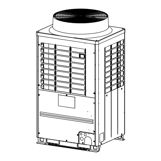
Outdoor Unit
Model name:
<Heat Pump Model>
MMY-MAP0806HT8P-ME
MMY-MAP1006HT8P-ME
MMY-MAP1206HT8P-ME
MMY-MAP10A6HT8P-ME
MMY-MAP12A6HT8P-ME
MMY-MAP1406HT8P-ME
MMY-MAP1606HT8P-ME
MMY-MAP14A6HT8P-ME
MMY-MAP16A6HT8P-ME
MMY-MAP1806HT8P-ME
MMY-MAP2006HT8P-ME
MMY-MAP0806HT8JPME
MMY-MAP1006HT8JPME
MMY-MAP1206HT8JPME
MMY-MAP10A6HT8JPME
MMY-MAP12A6HT8JPME
MMY-MAP1406HT8JPME
MMY-MAP1606HT8JPME
MMY-MAP14A6HT8JPME
MMY-MAP16A6HT8JPME
MMY-MAP1806HT8JPME
MMY-MAP2006HT8JPME
1117101401-3_EN.indd cover1
1117101401-3_EN.indd cover1
For commercial use
1117101401-3
Installation Manual
1
English
1/12/16 3:18 PM
1/12/16 3:18 PM
Advertisement
Table of Contents

Related Manuals for Toshiba MMY-MAP0806HT8P-ME


-
![Air Conditioner Toshiba MMY-MAP0804HT8JP Service Manual]()
Summary of Contents for Toshiba MMY-MAP0806HT8P-ME
- Page 1 1117101401-3 AIR CONDITIONER (MULTI TYPE) Installation Manual Outdoor Unit For commercial use Model name: <Heat Pump Model> MMY-MAP0806HT8P-ME MMY-MAP1006HT8P-ME MMY-MAP1206HT8P-ME MMY-MAP10A6HT8P-ME MMY-MAP12A6HT8P-ME MMY-MAP1406HT8P-ME MMY-MAP1606HT8P-ME MMY-MAP14A6HT8P-ME MMY-MAP16A6HT8P-ME MMY-MAP1806HT8P-ME MMY-MAP2006HT8P-ME MMY-MAP0806HT8JPME MMY-MAP1006HT8JPME MMY-MAP1206HT8JPME MMY-MAP10A6HT8JPME MMY-MAP12A6HT8JPME MMY-MAP1406HT8JPME MMY-MAP1606HT8JPME MMY-MAP14A6HT8JPME MMY-MAP16A6HT8JPME MMY-MAP1806HT8JPME MMY-MAP2006HT8JPME Installation Manual English 1117101401-3_EN.indd cover1...
-
Page 2: Table Of Contents
Toshiba Carrier 9 Address setting . - Page 3 ■ Warning indications on the air conditioner unit Definition of Protective Gear When the air conditioner is to be transported, installed, maintained, repaired or removed, wear protective gloves and ‘safety’ work clothing. Description Warning indication In addition to such normal protective gear, wear the protective gear described below when undertaking the special work detailed in the table below.
-
Page 4: Precautions For Safety
fi re, electric shocks, injury, water leakage, noise and/or vibration may result. completely may cause the air conditioner to malfunction. • If using separately sold products, make sure to use Toshiba specifi ed products only. Using unspecifi ed products may cause • Nitrogen gas must be used for the airtight test. -
Page 5: Accessory Parts
Accessory parts Relocation • Only a qualifi ed installer(*1) or qualifi ed service person(*1) is allowed to relocate the air conditioner. It is dangerous for the air conditioner to be relocated by an unqualifi ed individual since a fi re, electric shocks, injury, water leakage, noise and/or vibration may result. -
Page 6: Installation Of New Refrigerant Air Conditioner
– 5 – Installation of new refrigerant air Selection of installation place conditioner Upon customer’s approval, install the air conditioner in a place which satisfies the following conditions: • Place where it can be installed horizontally. • Place which can reserve a suffi cient service space for safe maintenance or checks. This air conditioner adopts the new HFC refrigerant (R410A) which does not deplete the ozone layer. - Page 7 ■ Installation space ▼ Combination of outdoor units Model name Leave space necessary for running, installation and servicing. Unit 1 Unit 2 Unit 3 (Standard type) MMY-MAP0806* MMY-MAP0806* – – Air discharge MMY-MAP1006* MMY-MAP1006* – – Air intake MMY-MAP1206* MMY-MAP1206* –...
-
Page 8: Carrying In The Outdoor Unit
– 7 – Carrying in the outdoor unit ■ Weight centre and weight ◆ Weight centre of an outdoor unit CAUTION Handle the outdoor unit carefully, observing the following items. Anchor bolt position Anchor bolt position Anchor bolt position When using a forklift or other machinery for loading/unloading in transportation, insert the fork of the forklift into •... -
Page 9: Installation Of The Outdoor Unit
Installation of the outdoor unit • Anchor bolt positions are as shown below: 310 or 310 or Continuous hole more more (15 x 20 long hole) WARNING • Be sure to install the outdoor unit in a place able to bear its weight. If strength is insuffi... - Page 10 – 9 – 5. Be careful of the connecting arrangement of the header unit and follower units. Set the outdoor units in order of When drawing pipes downward capacity from the one with the largest capacity. (A (Header unit) ≥ B ≥ C) [Vertical connection of branch units] •...
-
Page 11: Refrigerant Piping
Refrigerant piping REQUIREMENT • For a Brazing work of the refrigerant pipes, be sure to use nitrogen gas in order to prevent oxidation of the inside of the pipes; otherwise clogging of the refrigerating cycle due to oxidized scale may occur. WARNING •... - Page 12 – 11 – Coupling size of brazed pipe Pipe-diameter Type Draw-out forward Draw-out downward Liquid Connected section Cut the L-shaped pipe at the horizontal straight Cut the L-shape pipe at the vertical straight External size Internal size section, then braze the supplied attachment pipe, section, then braze the supplied attachment MAP10A Ø22.2 Ø12.7...
- Page 13 Table 1 Outdoor unit Capacity code Max. No. of model name Equivalent to Equivalent to Capacity code indoor units Indoor unit (High-efficiency model) capacity Equivalent to capacity rank Equivalent to HP MMY-MAP0806* 22.4 capacity MMY-MAP10A6* 28.0 MMY-MAP12A6* 33.5 1.25 MMY-MAP14A6* 40.0 MMY-MAP16A6* 45.0...
- Page 14 – 13 – Header Follower Follower Piping parts Name Selection of pipe size Remarks unit A unit B unit C Connecting pipe size of outdoor unit Type Gas side Liquid side MMY-MAP0806* Ø19.1 Ø12.7 Outdoor unit MMY-MAP1006* Ø22.2 Ø12.7 Outdoor unit MMY-MAP1206* Ø28.6 Ø12.7...
- Page 15 ■ Allowable length of refrigerant pipes and allowable height Piping parts Name Selection of pipe size Remarks difference between units Connecting pipe size of indoor unit Liquid Capacity rank Gas side side 15m or less real length Ø9.5 Ø6.4 Branching section Indoor unit 007 to 012 type Follower unit...
- Page 16 – 15 – ◆ Allowable length and allowable height difference of refrigerant piping WARNING Allowable Item Piping section Never use oxygen, flammable gases, or noxious gases in an airtight test. value Below 34HP 300m LA + La + Lb + Lc + L1 + L2 + L3 + L4+ Total extension of pipe L5 +L6 + L7 + a + b + c + d + e + f + g + Low pressure...
- Page 17 ■ Vacuum drying ■ Adding refrigerant • Be sure to perform vacuuming from both liquid and gas sides. After finishing vacuuming, exchange the vacuum pump with a refrigerant canister and start additional charging of • Be sure to use a vacuum pump equipped with the counter-flow prevention function so that oil in the pump will refrigerant.
- Page 18 – 17 – ■ Full opening of the valve Compensation by System Combination Charged refrigerant System HP Open the valves of the outdoor unit fully. – – 11.5 -1.5 MAP140 MAP10A 10HP 10HP – – 11.5 -1.5 MAP080 MAP160 MAP12A 12HP 12HP –...
-
Page 19: Electric Wiring
Electric wiring ■ Heat insulation for pipe • Apply heat insulation of pipe separately at the liquid, gas, and balance sides. • Be sure to use thermal insulator resistant up to 120°C or higher for pipes at the gas side. WARNING ■... - Page 20 – 19 – ◆ Power wiring selection High-effi ciency model MCA: Minimum Circuit Amps • Select the power supply cabling of each outdoor unit from the following specifi cations: MOCP: Maximum Overcurrent Protection (Amps) Cable 5-core, in conformance with design H07 RN-F or 60245 IEC 66. •...
- Page 21 ■ Specifi cations for communication wiring Be sure to keep the rule of below tables about size and length of communication wiring. Central control ◆ Design of communication wiring controller Super modular multi system Summary of communication wiring Table-1 Header Header Follower Header...
- Page 22 – 21 – ◆ Group control through a Remote Controller Group control of multiple indoor units (8 units) through a single remote controller switch Indoor unit Power supply terminal block No.1 No.2 No.7 No.8 No.3 No.4 Clamp fi lter (only MAP14A, MAP16A, MAP180, MAP200 type) Cord clamps (A.B)
-
Page 23: Address Setting
Address setting Screw size and tightening torque Tightening torque Screw size On this unit, it is required to set the addresses of the indoor units before starting air conditioning. (N•m) Set the addresses following the steps below. Power supply terminal 2.5 to 3.0 Earth screw 5.5 to 6.6... - Page 24 – 23 – ◆ Address setting procedure 1 ◆ Address setting procedure 2 Turn on indoor units fi rst, and then turn on outdoor units. Set a system address for each system using SW13 and 14 on the interface P.C. board on the header outdoor unit of each system.
- Page 25 SW13 SW14 Connect the relay connectors between the [U1, U2] and [U3, U4] terminals of the header Line (system) address outdoor unit of each refrigerant line. – – – ✕ ✕ – – – ✕...
- Page 26 – 25 – Switch setting (setting example when controlling 2 or more refrigerant lines centrally) CAUTION Outdoor units (setting manually) Relay connector connection *The items in bold font must be set manually. Never connect relay connectors between the [U1, U2] and [U3, U4] terminals before completing address setting of Outdoor unit’s all the refrigerant lines.
- Page 27 ■ Confi rming the indoor unit <Line (system) address> To fi nd an indoor unit’s position from its NOTE address addresses and the position Push the TEMP. buttons 1. Do not use address numbers 29 or 30 when setting repeatedly to set the CODE No. to of an indoor unit using the ▼...
- Page 28 – 27 – ■ Changing the indoor unit ▼ To change all the indoor unit addresses Push the button (left side of the using an arbitrary wired remote controller. address using a remote button) repeatedly to select another indoor CODE No. (The method is available when the addresses UNIT No.
- Page 29 ■ Resetting the address Push the button. Central control The address of one of the indoor units (Resetting to the factory controller • connected to the selected refrigerant line is default (address undecided)) indicated on the LCD display and the fan and louvers of the unit are activated.
-
Page 30: Test Run
– 29 – Test run ◆ When executing a test run using 2, 4 NOTE TEMP. ON / OFF the interface P.C. board on the • The running mode follows the mode setting on the TIMER SET outdoor unit remote controller of the target indoor unit. ■... - Page 31 <Corrective trial> Interface PC board SW04 SW05 SW15 ▼ Start operation Push switch Push switch Set the rotary switches on the interface P.C. board of the header outdoor unit as below. D600 D601 D602 D603 D604 When in “COOL” mode: SW01=[2], SW02=[5], SW03=[1]. 7-segment 7-segment display [A]...
-
Page 32: Troubleshooting
– 31 – Troubleshooting Check code Indication on 7-segment display on the outdoor unit Check code name In addition to the CODE No. on the remote controller of an indoor unit, you can diagnose failure type of an outdoor Auxiliary code unit by checking the 7-segment display on the interface P.C. -
Page 33: Machine Card And Logbook
Check code Machine card and logbook Indication on 7-segment display on the outdoor unit Check code name Auxiliary code 01: Compressor 1 Heat sink overheat error ■ Machine card 02: Compressor 2 Detected indoor unit address Indoor overflow error After test run, fill the items on the machine card and paste the card on an accessible place on the product securely —... - Page 34 – 33 – MEMO ......................................................................................................................................................................................................................................................................................................................................................................................................................................................................................................................................................................................................................................................................................................................................................
- Page 35 MEMO ................................................................................................................................................................................................................................................................................................................................................................................................................................................................................................................................................................................................................................................................................................................................................................................................................
- Page 36 WARNINGS ON REFRIGERANT LEAKAGE Check of Concentration Limit Important The room in which the air conditioner is to be installed NOTE 2 : requires a design that in the event of refrigerant gas The standards for minimum room volume are as leaking out, its concentration will not exceed a set limit.


