Table of Contents
Advertisement
1117701501
AIR CONDITIONER (MULTI TYPE)
Installation Manual
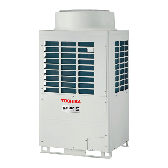
Outdoor Unit
For commercial use
Model name:
MMY-MAP0806FT8P-UK
MMY-MAP1006FT8P-UK
MMY-MAP1206FT8P-UK
MMY-MAP1406FT8P-UK
MMY-MAP1606FT8P-UK
MMY-MAP1806FT8P-UK
MMY-MAP2006FT8P-UK
MMY-MAP0806FT8JPUK
MMY-MAP1006FT8JPUK
MMY-MAP1206FT8JPUK
MMY-MAP1406FT8JPUK
MMY-MAP1606FT8JPUK
MMY-MAP1806FT8JPUK
MMY-MAP2006FT8JPUK
English
AMP Air Conditioning
www.ampair.co.uk | sales@ampair.co.uk
Advertisement
Table of Contents

Related Manuals for Toshiba MMY-MAP1006FT8P-UK
-
![Air Conditioner Toshiba MMY-MAP0806FT8P-TR Service Manual]()
-
![Air Conditioner Toshiba MMY-MAP0804HT8 Owner's Manual]()
-
![Air Conditioner Toshiba MMY-MAP0804HT8(Z)(ZG)-E Service Manual]()
-
![Air Conditioner Toshiba Super MMU-AP0091H Service Manual]()
-
![Air Conditioner Toshiba MMU-AP0091H Installation Manual]()
-
![Air Conditioner Toshiba Super Modular Unit MMU-AP0091H Installation Manual]()
-
![Air Conditioner Toshiba MMY-MAP0804HT8JP Service Manual]()
Summary of Contents for Toshiba MMY-MAP1006FT8P-UK
-
Page 1: Installation Manual
1117701501 AIR CONDITIONER (MULTI TYPE) Installation Manual Outdoor Unit For commercial use Model name: MMY-MAP0806FT8P-UK MMY-MAP1006FT8P-UK MMY-MAP1206FT8P-UK MMY-MAP1406FT8P-UK MMY-MAP1606FT8P-UK MMY-MAP1806FT8P-UK MMY-MAP2006FT8P-UK MMY-MAP0806FT8JPUK MMY-MAP1006FT8JPUK MMY-MAP1206FT8JPUK MMY-MAP1406FT8JPUK MMY-MAP1606FT8JPUK MMY-MAP1806FT8JPUK MMY-MAP2006FT8JPUK English AMP Air Conditioning www.ampair.co.uk | sales@ampair.co.uk... -
Page 2: Table Of Contents
Toshiba Carrier Corporation or, alternatively, he or she has been instructed in such matters by an individual or individuals who Qualified service... -
Page 3: Warning Indications On The Air Conditioner Unit
Warning indications on the air conditioner unit Definition of Protective Gear When the air conditioner is to be transported, installed, maintained, repaired or removed, wear protective gloves and ‘safety’ work clothing. Warning indication Description In addition to such normal protective gear, wear the protective gear described below when undertaking the special work detailed in the table below. -
Page 4: Precautions For Safety
• If using separately sold products, make sure to use Toshiba in injury. specified products only. Using unspecified products may cause •... -
Page 5: Refrigerant Piping 1
• This appliance is intended to be used by expert or trained users Installation in shops, in light industry, or for commercial use by lay persons. • Follow the instructions in the Installation Manual to install the air conditioner. Failure to follow these instructions may cause the •... -
Page 6: Address Setting 2
– 5 – • After the installation work, confirm that refrigerant gas does • Use wiring that meets the specifications in the Installation not leak. If refrigerant gas leaks into the room and flows near Manual and the stipulations in the local regulations and laws. a fire source, such as a cooking range, noxious gas may be Use of wiring which does not meet the specifications may give generated. - Page 7 Test run • If you have discovered that the fan grille is damaged, do not • Before operating the air conditioner after having completed the approach the outdoor unit but set the circuit breaker to the OFF work, check that the electrical parts box cover of the indoor unit position, and contact a qualified service person(*1) to have the and service panel of the outdoor unit are closed, and set the repairs done.
- Page 8 – 7 – CAUTION New refrigerant air conditioner installation • This air conditioner adopts the new HFC refrigerant (R410A) which does not destroy ozone layer. • The characteristics of R410A refrigerant are; easy to absorb water, oxidizing membrane or oil, and its pressure is approx. 1.6 times higher than that of refrigerant R22.
-
Page 9: Accessory Parts
Accessory parts Q’ty Q’ty MAP160 MAP160 Part name Shape Usage Part name Shape Usage MAP080 MAP080 MAP120 MAP140 MAP180 MAP120 MAP140 MAP180 MAP100 MAP100 MAP200 MAP200 (Be sure to hand it to the Owner’s Manual – Attached pipe customers.) (Ø12.7 for draw-out –... -
Page 10: Installation Of New Refrigerant Air Conditioner
– 9 – Installation of new refrigerant air conditioner Selection of installation place This air conditioner adopts the new HFC refrigerant (R410A) which does not deplete the ozone layer. Upon customer’s approval, install the air conditioner in a place which satisfies the following conditions: •... -
Page 11: Installation Space
Installation space q Combination of outdoor units (* : FT8P-UK , FT8JPUK ) Model name Unit 1 Unit 2 Unit 3 Leave space necessary for running, installation and servicing. MMY-MAP0806* MMY-MAP0806* MMY-MAP1006* MMY-MAP1006* Air discharge MMY-MAP1206* MMY-MAP1206* Air intake MMY-MAP1406* MMY-MAP1406* MMY-MAP1606* MMY-MAP1606*... -
Page 12: Carrying In The Outdoor Unit
– 1 1 – Carrying in the outdoor unit Weight centre and weight CAUTION ¿ Weight centre of an outdoor unit Handle the outdoor unit carefully, observing the following items. • When using a forklift or other machinery for loading/unloading in transportation, insert the fork of the forklift into Anchor bolt position Anchor bolt position Anchor bolt position... -
Page 13: Installation Of The Outdoor Unit
Installation of the outdoor unit • Anchor bolt positions are as shown below: 310 or 310 or Continuous hole more more WARNING (15 x 20 long hole) • Be sure to install the outdoor unit in a place able to bear its weight. If strength is insufficient, the unit may fall down resulting in human injury. - Page 14 – 13 – 5. Be careful of the connecting arrangement of the header unit and follower units. Set the outdoor units in order of <Upright connection of suction gas joint> capacity from the one with the largest capacity. (A (Header unit) ≥ B ≥ C) q Figure 5 •...
-
Page 15: Refrigerant Piping
Refrigerant piping REQUIREMENT • For Brazing work of the refrigerant pipes, be sure to use nitrogen gas in order to prevent oxidation of the inside of the pipes; otherwise clogging of the refrigerating cycle due to oxidized scale may occur. WARNING •... - Page 16 – 1 5 – Extruding margin of copper pipe with flare machining: B (Unit: mm) Coupling size of brazed pipe Copper pipe outer When using R410A When using Connected section dia. tool conventional tool External size Internal size 12.7 0 to 0.5 1.0 to 1.5 15.9 19.1...
- Page 17 Table 1 Capacity code Indoor unit Equivalent to capacity rank Equivalent to HP capacity *005 1.25 11.2 22.4 *005 Indoor model: MMU-AP0056MH*, MMD-AP0056SPH*, MMK-AP0054MHP* Table 2 Capacity code Outdoor unit Max. No. of model name*1 Equivalent to indoor units*2 Equivalent to HP (Standard model) capacity MMY-MAP0806*...
- Page 18 – 1 7 – Header Follower Follower unit A unit B unit C (8) Branching header Outdoor unit (7) Y-shaped branching joint Balance (4)*2 pipes Ø9.5 (10) (10) Liquid pipe Discharge-side Cooling only Cooling only gas pipe Suction-side gas pipe (4)*2 (10) (4)*2...
- Page 19 Selection of pipe size Title Use part Selection of pipe size Remarks Terminal Title Use part Selection of pipe size Remarks Equivalent to Capacity rank Length of piping Gas side Liquid side branching section Ô 15 m or less real length Ø9.5 Ø6.4 Balance pipe...
- Page 20 – 1 9 – Allowable length of refrigerant pipes and allowable height ¿ System restriction difference between units Outdoor unit combination Up to 3 units Total capacity of outdoor units Up to 42 HP Indoor unit connection Up to 64 units (*1) Outdoor unit Total capacity of indoor units H2 ≤...
-
Page 21: Airtightness Test
*10: Extension up till 90 m is possible with conditions below ¿ Allowable length and allowable height difference of refrigerant piping - Outdoor Temperature Cooling : 10°C to 46°C (Dry-bulb temp.) Heating : -5°C to 15°C (Wet-bulb temp.) Allowable Item Pipes Simultaneous operating : 7°C to 25°C (Dry-bulb temp.) value... -
Page 22: Vacuum Drying
– 2 1 – Able to detect a serious leakage Vacuum drying 1. Apply pressure 0.3MPa (3.0kg/cm G) for 5 minutes or more. 2. Apply pressure 1.5MPa (15kg/cm G) for 5 minutes or more. • Be sure to use a vacuum pump equipped with the counter-flow prevention function so that oil in the pump will not flow back into piping for air conditioners. -
Page 23: Adding Refrigerant
Adding refrigerant Table 2 Combination of outdoor unit Model name of Corrective of After finishing vacuuming, exchange the vacuum pump with a refrigerant canister and start additional charging of Equivalent MMY- outdoor unit refrigerant refrigerant. MMY- (kg) Unit 1 Unit 2 Unit 3 MAP0806* MAP0806*... - Page 24 – 2 3 – Full opening of the valve F-GAS label Open the valves of the outdoor unit fully. This product contains fluorinated greenhouse gases • Chemical Name of Gas R410A MAP120 • Global Warming Potential (GWP) of Gas 2088 (ex.R410A ref.AR4) MAP140 MAP080 MAP160...
-
Page 25: Electric Wiring
Electric wiring Heat insulation for pipe • Apply heat insulation of pipe separately at the liquid, gas, and balance sides. • Be sure to use thermal insulator resistant up to 120°C or higher for pipes at the gas side. WARNING The appliance shall be installed in accordance with national wiring regulations. - Page 26 – 2 5 – ¿ Power wiring selection Specifications for communication wiring • Select the power supply cabling of each outdoor unit from the following specifications: Cable 5-core, in conformance with design H07 RN-F or 60245 IEC 66. ¿ Design of communication wiring •...
- Page 27 Restriction of control wiring ¿ Group control through a Remote Controller Be sure to keep the rule of below tables about size and length of control wiring. Group control of multiple indoor units (8 units) through one or two remote controller switch Central Indoor unit control...
- Page 28 – 2 7 – Screw size and tightening torque Tightening torque Screw size (N•m) Power supply terminal block Power supply terminal 2.5 to 3.0 Earth screw 5.5 to 6.6 Clamp filter (only MAP160 to MAP200 type) ¿ Communication wire connection Cord clamps Get the communication wire through the cutout on the side of the electrical control box and connect it to the communication wire terminals, then fix it with the communication cable clamp.
-
Page 29: Address Setting
Address setting Regulation of high frequency wave On this unit, it is required to set the addresses of the indoor units before starting air conditioning. This equipment complies with IEC 61000-3-12 provided that the short-circuit power Ssc is greater than or equal to Ssc Set the addresses following the steps below. - Page 30 – 2 9 – ¿ Address setting procedure 1 ¿ Address setting procedure 2 Turn on indoor units first, and then turn on outdoor units. Set a system address for each system using SW13 and 14 on the interface P.C. board on the header outdoor unit of each system.
- Page 31 SW13 SW14 Connect the relay connectors between the [U1, U2] and [U3, U4] terminals of the header Line (system) address outdoor unit of each refrigerant line. ™ ™ Í Í ™ ― ― ― Í Í ― ― ― ™ ™...
- Page 32 – 3 1 – Switch setting (setting example when controlling 2 or more refrigerant lines centrally) CAUTION Outdoor units (setting manually) *The items in bold font must be set manually. Relay connector connection Never connect relay connectors between the [U1, U2] and [U3, U4] terminals before completing address setting of Outdoor unit’s Follower Follower...
- Page 33 Confirming the indoor unit To find an indoor unit’s position from its <Line (system) address> NOTE address addresses and the position 1. Do not use address numbers 29 or 30 when setting Push the TEMP. buttons q When checking unit numbers controlled as a system addresses using the remote controller.
- Page 34 – 3 3 – Changing the indoor unit q To change all the indoor unit addresses Push the button (left side of the using an arbitrary wired remote controller. address using a remote button) repeatedly to select another indoor CODE No. (The method is available when the addresses DATA SETTING...
- Page 35 Resetting the address Central control Push the button. controller (Resetting to the factory • The address of one of the indoor units connected to the selected refrigerant line is default (address undecided)) indicated on the LCD display and the fan and Header Header Header...
- Page 36 – 35 – Setting when connecting ¿ How to set up CODE No. [ 0E ] q In case of FE/FD without setting q In case of FE/FD with setting indoor units to FS (Flow It is necessary to set up in case of the group control. Single port type FS unit Single port type FS unit Selector) unit...
- Page 37 ¿ [ Set up example ] <In case of connecting one group operation of <In case of connecting one group operation of <Incorrect connection examples> indoor units> indoor units and two indoor units> Incorrect Single port type FS unit Single port type FS unit [ 0E ] : Group setting Single port type FS unit Piping...
-
Page 38: How To Set Up The Cooling Only Indoor Unit
– 3 7 – How to set up the cooling only indoor unit When the setup finished, push button. (The setup is determined.) When setting the specific indoor unit to Cooling Only Pushing button deletes the display and In a group control, the firstly displayed unit without connecting to the flow selector unit, setup returns to normal stop status. -
Page 39: Test Run
Test run ¿ When executing a test run using NOTE TEMP. ON / OFF 2, 4 the interface P.C. board on the • The running mode follows the mode setting on the Before test run TIMER SET outdoor unit remote controller of the target indoor unit. •... - Page 40 – 3 9 – <Corrective trial> Interface PC board q Start operation SW04 SW05 SW15 Push switch Push switch Set the rotary switches on the interface P.C. board of the header outdoor unit as below. D600 D601 D602 D603 D604 When in “COOL”...
-
Page 41: Troubleshooting
Troubleshooting Check code Indication on 7-segment display on the outdoor unit Check code name In addition to the CODE No. on the remote controller of an indoor unit, you can diagnose failure type of an outdoor Auxiliary code unit by checking the 7-segment display on the interface P.C. board. 01: TS1 sensor TS1 or TS2 sensor error Use the function for various checks. -
Page 42: Machine Card And Logbook
– 4 1 – Machine card and logbook Check code Indication on 7-segment display on the outdoor unit Check code name Machine card Auxiliary code — Discharge temperature TD1 error After test run, fill the items on the machine card and paste the card on an accessible place on the product securely 01: Compressor 1 High-pressure SW system operation before delivery to the customer. - Page 43 (1) No partition (shaded portion) limit. Google Inc. The refrigerant R410A which is used in the air conditioner URL : http://www.toshiba-carrier.co.jp/global/appli/smms_wave_tool/ is safe, without the toxicity or combustibility of ammonia, QR code and is not restricted by laws to be imposed which protect NOTICE the ozone layer.
- Page 44 144 / 9 Moo 5, Bangkadi Industrial Park, Tivanon Road, Tambol Bangkadi, Amphur Muang, Pathumthani 12000, Thailand 1117701501 AMP Air Conditioning www.ampair.co.uk | sales@ampair.co.uk...
-


