
Related Manuals for Dell PowerEdge XR4000z


Summary of Contents for Dell PowerEdge XR4000z
- Page 1 Dell PowerEdge XR4000z Installation and Service Manual Regulatory Model: E99S Regulatory Type: E99S001 December 2022 Rev. A00...
- Page 2 A WARNING indicates a potential for property damage, personal injury, or death. © 2022 Dell Inc. or its subsidiaries. All rights reserved. Dell Technologies, Dell, and other trademarks are trademarks of Dell Inc. or its subsidiaries. Other trademarks may be trademarks of their respective owners.
-
Page 3: Table Of Contents
Contents Chapter 1: About this document....................5 Chapter 2: Dell PowerEdge XR4000z system configurations and features ........6 System configurations - front view for PowerEdge XR4000z.................6 System configurations - rear view for PowerEdge XR4000r................... 7 Power supply unit indicator codes...........................8 Locating the Express Service Code and Service Tag....................9... - Page 4 Chapter 6: Getting help.......................45 Recycling or End-of-Life service information......................45 Contacting Dell Technologies............................45 Accessing system information by using QRL......................45 Quick Resource Locator for PowerEdge XR4000z system................46 Receiving automated support with SupportAssist ....................46 Chapter 7: Documentation resources................... 47 Contents...
-
Page 5: Chapter 1: About This Document
About this document This document provides an overview about the system, information about installing and replacing components, diagnostic tools, and guidelines to be followed while installing certain components. About this document... -
Page 6: Chapter 2: Dell Poweredge Xr4000Z System Configurations And Features
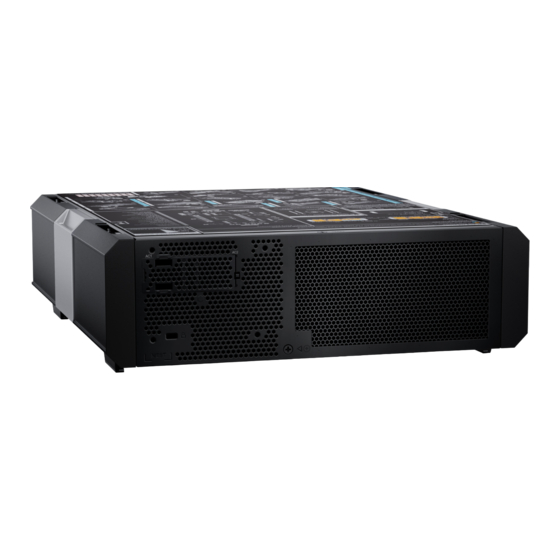
Dell PowerEdge XR4000z system configurations and features The PowerEdge XR4000z system is a 2U stackable chassis that supports: ● Up to two XR4510c 1U, 1-socket server sled or one XR4520c 2U, 1-socket server sled and one optional nano-server (witness sled XR4000w) example vSAN. -
Page 7: System Configurations - Rear View For Poweredge Xr4000R
Indicates PSU 2. Information tag The Information tag is a slide-out label panel that contains one MAC address and EST. System configurations - rear view for PowerEdge XR4000r Figure 3. Rear view of the system Dell PowerEdge XR4000z system configurations and features... -
Page 8: Power Supply Unit Indicator Codes
This results in a PSU mismatch condition or failure to power on the system. CAUTION: If two PSUs are used, they must be of the same type and have the same maximum output power. Dell PowerEdge XR4000z system configurations and features... -
Page 9: Locating The Express Service Code And Service Tag
The unique Express Service Code and Service Tag are used to identify the system. The information tag is located on the rear of the system that includes system information such as iDRAC MAC address, Express Service Tag label. Dell PowerEdge XR4000z system configurations and features... -
Page 10: System Information Label
The Mini Enterprise Service Tag (MEST) label is located on the system. The MEST includes the Service Tag (ST), Express Service Code (Exp Svc Code), and Manufacture Date (Mfg. Date). The Exp Svc Code is used by Dell EMC to route support calls to the appropriate personnel. -
Page 11: Rail Sizing And Rack Compatibility Matrix
Figure 7. System tasks, Figure 8. Bezel tasks Rail sizing and rack compatibility matrix For specific information about the rail solutions compatible with your system, see the Dell Enterprise Systems Rail Sizing and Rack Compatibility Matrix available at https://i.dell.com/sites/csdocuments/Business_solutions_engineering- Docs_Documents/en/rail-rack-matrix.pdf. -
Page 12: Chapter 3: Technical Specifications
Technical specifications The technical and environmental specifications of your system are outlined in this section. Topics: • Chassis dimensions • System weight • Witness cooling fan specifications • PSU specifications • Power module assembly • Supported operating systems • PowerEdge XR sleds ports and connectors •... -
Page 13: Chassis Dimensions
Chassis dimensions Figure 9. Chassis dimensions Table 6. PowerEdge XR4000z chassis dimensions without side panels and bezel 266 mm (10.47 inches) 266 mm (10.47 87.05 mm (3.42 10 mm (0.39 inches) 355 mm (13.97 20.20 mm (0.79 inches) inches) inches) -
Page 14: System Weight
Recommend three person to lift ≥ 121 pounds Recommend to use a server-lift Witness cooling fan specifications The PowerEdge XR4000z system supports one standard fan with reverse air flow (RAF) for witness sled cooling. Table 10. Cooling fan specifications Fan type Label color... -
Page 15: Power Module Assembly
Power module assembly The Dell PowerEdge XR4000z a power module assembly which consists of two power distribution board (PDB's) and are connected to each other so either or both power supplies can power the whole chassis. The power distribution board (PDB) at the bottom also has chassis manager board to manage the chassis and the optional witness sled. -
Page 16: Supported Operating Systems
(CM) is responsible for the witness fan operations. Supported operating systems The PowerEdge XR4000z system supports the following operating systems: ● Azure Stack HCI ● Canonical Ubuntu Server LTS ● Microsoft Windows Server with Hyper-V (support only from July’23) ●... -
Page 17: Poweredge Xr4000W
Ambient temperature for rear air-fllow (RAF) 45°C with GPU Non-operating temperature range -40 to 85°C Environmental Considerations The PowerEdge XR4000z system is targeted for edge deployments and it meets all the additional standards for thermal, shock, vibration parameters. Table 17. Environmental considerations Industry Configuration Description... -
Page 18: Thermal Restriction Matrix
Table 17. Environmental considerations (continued) Industry Configuration Description MILSTD 1474E Department of Defense Design Criteria Standard Noise Limits Marine IEC-60945 Maritime navigation and radiocommunication equipment and systems – General requirements DNV-GL Environmental Test Specification for Instrumentation and Automation Equipment Power Industry IEEE 1613 Environmental and testing requirements for communications networking devices in electric power... - Page 19 Table 20. M.2 Support Thermal Limitation for XR4000z chassis (RAF Configurations) (continued) Riser Module Mancini Module AIC Card M.2 Module (Witness Type Sled) Edge 2 Edge 1 ASHRAE Edge 2 Edge 1 ASHRA Edge 2 Edge 1 ASHRA Edge 2 Edge 1 ASHRA (Max (Max...
- Page 20 ● Nvidia A30 card is not supported above 45°C ambient temperature. ● Nvidia A2 GPU card is not supported above 45°C ambient temperature. ● In redundant mode, two power supplies are required. A single power supply failure is not supported. ●...
-
Page 21: Chapter 4: Minimum Configuration To Post
Minimum configuration to POST The components listed below are the minimum configuration to POST: ● One XR4510c or XR420c sled ● One memory module (DIMM) in socket A1 of the sled ● One power supply unit Minimum configuration to POST... -
Page 22: Chapter 5: Installing And Removing System Components
Damage due to servicing that is not authorized by Dell is not covered by your warranty. Read and follow the safety instructions that are shipped with your product. -
Page 23: Before Working Inside Your System
Follow the safety guidelines listed in the Safety instructions. Steps If applicable, remove the system from the rack. For more information, see the Rail Installation Guide relevant to your rail solutions at www.dell.com/poweredgemanuals. After working inside your system Prerequisites Follow the safety guidelines listed in Safety instructions. -
Page 24: Installing The Front Bezel
NOTE: The bezel key is part of the bezel package. Steps 1. Unlock the bezel. 2. Press the release button on both sides of the bezel. 3. Pull the bezel out of the enclosure. NOTE: The numbers on the image do not depict the exact steps. The numbers are for representation of sequence. Figure 11. -
Page 25: Bezel Filter
Figure 12. Installing the front bezel Bezel filter Removal and installation of the bezel filter Prerequisites 1. Follow the safety guidelines listed in the Safety instructions. 2. Follow the procedure listed in the Before working inside your system. Remove the front bezel. - Page 26 Figure 14. Removal and installation of the bezel filter NOTE: To maintain optimal system health, Dell Technologies recommends checking and changing the filter every three months. Filters can be ordered from Dell. 3. Align both the latches on the grill into to the bezel latch slots and push until the grill locks into place.
-
Page 27: Side Panel
Figure 15. Installing the grill into the bezel Side panel Removing the side panel Prerequisites 1. Follow the safety guidelines listed in the Safety instructions. 2. Remove the front bezel, if applicable. Steps 1. Push the spring-latch to disengage the side panel from the chassis. 2. -
Page 28: Installing The Side Panel
Figure 16. Removing the side panel Next steps Installing the side panel Installing the side panel Prerequisites 1. Follow the safety guidelines listed in the Safety instructions. 2. Remove the front bezel, if applicable. Steps Align the guide pins on the side panels with the guides on the system and slide the side panel toward the front side to engage the spring latch. -
Page 29: Xr4000Z Sled
Figure 17. Installing the side panel Next steps Install the sled. 2. Follow the procedure listed in After working inside your system. XR4000z sled Removing a sled blank Prerequisites Follow the safety guidelines listed in Safety instructions. Steps Pull the sled blank to remove it from the enclosure. Installing and removing system components... -
Page 30: Installing A Sled Blank
Figure 18. Removing the rear cover Next steps Install a sled sled blank. Installing a sled blank Prerequisites Follow the safety guidelines listed in Safety instructions. Steps 1. Align the sled blank with the bay of the chassis. 2. Insert and push the sled blank, until it locks into place. Installing and removing system components... -
Page 31: Removing A Sled
Figure 19. Installing the sled blank Removing a sled Prerequisites 1. Follow the safety guidelines listed in the Safety instructions. 2. Remove the front bezel, if applicable. Steps 1. Pull the blue lever on the sled to release the sled handle. 2. -
Page 32: Installing A Sled
Figure 20. Removing a 1U sled from XR4000z Figure 21. Removing a 2U sled from XR4000z Next steps Installing the sled Installing a sled Prerequisites Follow the safety guidelines listed in Safety instructions. Installing and removing system components... - Page 33 Steps 1. Pull the blue lever on the sled to free the sled handle. 2. Holding the sled with both hands, align the sled along the sled-bay in to the chassis. 3. Slide the sled into the chassis, ensure the sled handle is in lock position. 4.
-
Page 34: Rear Cover
Next steps 1. Install the front bezel. 2. Follow the procedure listed in After working inside your system. Rear cover Removing the rear cover Prerequisites Follow the safety guidelines listed in the Safety instructions. Steps 1. Using the Torx #8 screwdriver, remove the screws that secures the rear cover on to the chassis. 2. -
Page 35: Power Module Assembly
Figure 25. Installing the rear cover Power module assembly Removing power module assembly Prerequisites 1. Follow the safety guidelines listed in the Safety instructions. Remove the rear cover. 3. Remove the sleds. 4. Remove the witness sled. 5. Remove the power supply units. -
Page 36: Installing The Power Module Assembly
Figure 26. Removing power module assembly Next steps Replace power module assembly. Installing the power module assembly Prerequisites Follow the safety guidelines listed in the Safety instructions. Steps 1. Align and insert the power tray along with the power module assembly (PDB) into the chassis. 2. -
Page 37: Cooling Fans
Next steps Follow the procedure listed in After working inside your system.. Cooling fans Removing the witness fan Prerequisites 1. Follow the safety guidelines listed in the Safety instructions. Remove the rear cover. Remove the power module assembly. Steps 1. Using the Phillips 2 screwdriver, remove the screw connected to the power distribution board (PDB) . 2. -
Page 38: Power Supply Unit
While replacing the hot swappable PSU, after next server boot; the new PSU automatically updates to the same firmware and configuration of the replaced one. For updating to the latest firmware and changing the configuration, see the Lifecycle Controller User's Guide at https://www.dell.com/idracmanuals. Removing a power supply unit blank... -
Page 39: Removing A Power Supply Unit
2. Disconnect the power cable from the power outlet and from the Power Supply Unit (PSU) you intend to remove. 3. Remove the cable from the strap on the PSU handle. NOTE: The PowerEdge XR4000z only supports reverse air flow Power Supply Units (PSUs). The PSUs with blue straps are designed for reverse air flow (RAF). Steps Press the orange release latch, and holding the PSU handle slide the PSU out of the PSU bay. -
Page 40: Installing A Power Supply Unit Blank
While replacing the hot swappable PSU, after next server boot; the new PSU automatically updates to the same firmware and configuration of the replaced one. For more information about the Part replacement configuration, see the Lifecycle Controller User's Guide at https://www.dell.com/idracmanuals Installing a power supply unit blank Prerequisites 1. -
Page 41: Witness Sled
Figure 33. Installing a power supply unit blank Witness sled Removing a witness sled blank Prerequisites Follow the safety guidelines listed in Safety instructions. Steps 1. Pull up the plunger located on the witness sled blank. 2. Remove the witness sled blank. NOTE: The numbers on the image do not depict the exact steps. -
Page 42: Installing A Witness Sled Blank
Installing a witness sled blank Prerequisites Follow the safety guidelines listed in Safety instructions. Steps 1. Align the sled blank with the bay of the chassis. 2. Insert and push the sled blank until the plunger locks into place. NOTE: The numbers on the image do not depict the exact steps. -
Page 43: Installing The Witness Sled
Figure 36. Removing the witness sled Next steps Replace witness sled. Installing the witness sled Prerequisites Follow the safety guidelines listed in the Safety instructions. Steps 1. Align and insert the witness sled into chassis. 2. Using the witness sled handle, slide the sled until it locks into place. Installing and removing system components... - Page 44 Figure 37. Installing the witness sled Next steps Connect all the cables and peripherals. Installing and removing system components...
-
Page 45: Chapter 6: Getting Help
Dell contact information on your purchase invoice, packing slip, bill or Dell product catalog. The availability of services varies depending on the country and product, and some services may not be available in your area. To contact Dell for sales, technical... -
Page 46: Quick Resource Locator For Poweredge Xr4000Z System
Dell. This information is used by Dell Technical Support to troubleshoot the issue. ● Proactive contact — A Dell Technical Support agent contacts you about the support case and helps you resolve the issue. The available benefits vary depending on the Dell Service entitlement purchased for your device. For more information about SupportAssist, go to www.dell.com/supportassist. -
Page 47: Chapter 7: Documentation Resources
This section provides information about the documentation resources for your system. To view the document that is listed in the documentation resources table: ● From the Dell support site: 1. Click the documentation link that is provided in the Location column in the table. - Page 48 Methods to download firmware and drivers section in this document. Managing your system For information about systems management www.dell.com/poweredgemanuals software offered by Dell, see the Dell OpenManage Systems Management Overview Guide. For information about setting up, using, www.dell.com/openmanagemanuals >...