
Related Manuals for Motorola IXP/CPCI-9120


Summary of Contents for Motorola IXP/CPCI-9120
- Page 1 All manuals and user guides at all-guides.com sales@artisantg.com artisantg.com (217) 352-9330 | Click HERE Find the Emerson / Motorola / Force Computers CPCI-9120 at our website:...
- Page 2 All manuals and user guides at all-guides.com IXP/CPCI-9120 Reference Guide 6806800A77B October 2006...
- Page 3 Printed in the United States of America. Trademarks Motorola® and the stylized M logo are trademarks of Motorola, Inc., registered in the U.S. Patent and Trademark Office. All other names, products, or services mentioned in this document may be trademarks or registered...
- Page 4 Motorola reserves the right to revise this document and to make changes from time to time in the content hereof without obligation of Motorola to notify any person of such revision or changes.
- Page 5 All manuals and user guides at all-guides.com...
-
Page 6: Table Of Contents
PMC Module ..............47 IXP/CPCI-9120... - Page 7 IXP/CPCI-9120 Board Installation ........
- Page 8 BIB I2C Memory Map ............102 IXP/CPCI-9120...
- Page 9 Diagnostics ..............122 IXP/CPCI-9120...
- Page 10 Board Diagnostics Commands ........... . . 146 Troubleshooting Index IXP/CPCI-9120...
- Page 11 All manuals and user guides at all-guides.com IXP/CPCI-9120...
- Page 12 Interrupt Status Register-2 ..........111 IXP/CPCI-9120...
- Page 13 Interrupt Status Register ..........116 RedBoot Diagnostics Troubleshooting IXP/CPCI-9120...
- Page 14 IXP/CPCI-9120 with the installed PMC ........
- Page 15 All manuals and user guides at all-guides.com Diagnostics Troubleshooting IXP/CPCI-9120...
- Page 16 Data Paths etc., used on the blade and how they are interconnected Daughter Card Details IXP/CPCI-9120 has two daughter cards, one of which provides I/O and the other provides additional SRAM. Maps and Registers Provides information that is relevant for programmers, such as register...
- Page 17 Repeated item, e.g. node 1, node 2, ..., node 12 Omission of information from example/command that is not necessary at the time being Ranges, e.g.: 0..4 means one of the integers 0, 1, 2, 3, and 4 (used in registers) Logical OR IXP/CPCI-9120...
- Page 18 Electrostatic Discharge Field Replaceable Unit GPIO General Purpose Input/output Inter IC Communication Input/Output IBMU Intelligent Board Management Unit ICMB Intelligent Chassis Management Bus IEEE Institute of Electrical and Electronic Engineers IPMB Intelligent Platform Management Bus IPMI Intelligent Platform Management Interface IXP/CPCI-9120...
- Page 19 PCI Mezzanine Card PPMC/PrMC Processor PCI Mezzanine Card Packet Over Sonet POS-PHY Packet Over Sonet PHYsical Layer device Packet Switching Backplane POSIX Portable Operating Systems Interface Quad Data Rate Reserved for Future Use RGMII Reduced Gigabit Media Independent Interface IXP/CPCI-9120...
- Page 20 Updated Table of PCI Memory Map in Maps and Registers chapter Changes in Daughter Card Details chapter Three commands added to Diagnostics chapter 224535 420 000 August 2005 Added commands in RedBoot and Diagnostics chapters Additions to registers, changes in pinouts and switch settings. IXP/CPCI-9120...
- Page 21 Revision Date Description 6806800A77 June 2006 Updated with Motorola logo; formatted RedBoot commands; change and update in Part Numbers in Ordering Information and Accessories; name change to IXP/CPCI-9120; RoHS compliance added to Standards table; block diagrams updated. This manual has the new Part Number.
- Page 22 MV-S100707-00, Rev.C, November 12, 2003 PCISIG pcisig.com PCI Local Bus Specification 2.2 PICMG picmg.com PICMG 2.0 R3.0 PICMG picmg.com PICMG 2.1 R2.0 PICMG picmg.com PICMG 2.16 R1.0 PICMG picmg.com PICMG 2.9 R1.0 Summit Micro- summitmicro.com/home/ SMH4042 electronics Texas Instruments ti.com TPS54672 IXP/CPCI-9120...
- Page 23 All manuals and user guides at all-guides.com Company www. Document VITA Standards vita.com Processor PMC Standard, Organisation VITA 32 Draft 1.0a (VSO) Vitesse vitesse.com VSC215 Baseboard Management Controller Data Manual, Version 0.56, JAN/11/2001 IXP/CPCI-9120...
-
Page 24: Safety Notes
This section provides safety precautions to follow when installing, operating, and maintaining the IXP/CPCI-9120 and all sub-boards. We intend to provide all necessary information to install and handle the IXP/CPCI-9120 in this Reference Guide. However, as the product is complex and its usage manifold, we do not guarantee that the given information is complete. - Page 25 Hot Swap The IXP/CPCI-9120 provides hot-swap support, i.e. it may be installed in or removed from a powered system supporting hot swap. Never install the board in or remove it from a system under hot-swap conditions unless the basic hot-swap, full hot-swap or high-availability plat- form is used and the system documentation explicitly includes appropriate guidelines.
- Page 26 The length of the electric cable connected to a TPE bushing must not exceed 100 meter. If you have further questions, ask your system administrator. Environment Always dispose of old boards according to your country’s legislation, if possible in an environmentally acceptable way. IXP/CPCI-9120...
- Page 27 All manuals and user guides at all-guides.com IXP/CPCI-9120...
-
Page 28: Sicherheitshinweise
Anwendungen in der Telekommunikationsindustrie und im Zusammenhang mit Industriesteuerungen verwendet werden. Einbau, Wartung und Betrieb dürfen nur von durch Motorola ECC ausgebildetem oder im Bereich Elektronik oder Elektrotechnik qualifiziertem Personal durchgeführt werden. Die in diesem Handbuch enthaltenen Informationen dienen ausschließlich dazu, das Wissen von Fachpersonal zu ergänzen, können es aber in keinem Fall ersetzen. - Page 29 All manuals and user guides at all-guides.com Installation Elektrostatische Entladung und unsachgemäßer Ein- und Ausbau des Boards kann Schaltkreise beschädigen oder ihre Lebensdauer verkürzen. Beachten Sie deshalb die folgenden Punkte: • Lesen sie vor Ein- oder Ausbau des Boards den Abschnitt “Action Plan” auf Seite 2- 41"...
- Page 30 Stellen Sie sicher, dass Anschlüsse und Kabel des Boards während des Betriebs nicht berührt werden können. Austausch/Erweiterung Verwenden Sie bei Austausch oder Erweiterung nur von Motorola ECC empfohlene Komponenten und Systemteile. Andernfalls sind Sie für mögliche Auswirkungen auf EMV und geänderte Funktionalität des Produktes voll verantwortlich.
- Page 31 All manuals and user guides at all-guides.com...
-
Page 32: Introduction
All manuals and user guides at all-guides.com Introduction... - Page 33 All manuals and user guides at all-guides.com...
-
Page 34: Features
Features Features IXP/CPCI-9120 is a 6U 4HP CompactPCI Single Board Computer complex based on the Intel IXP2400 network processor for up to duplex OC-48 or 4 Gbit Ethernet bandwidth applica- tions. IXP/CPCI-9120 has a Processor PMC expansion for expandable Control plane process- ing power, a flexible media interface mezzanine to support different standard and OEM media flavors (e.g., Copper Ethernet, Fiber Ethernet, SONET/ATM, DS1/E1, etc.), and a SRAM... - Page 35 Features Introduction The 2.16 variant provides two Gigabit Ethernet ports on the PICMG 2.16 links. IXP/CPCI-9120 single slot board complex comprises of the following features: • Single-NPU Intel IXP2400 board at 600 MHz • 256 MB SO-DIMM DDRSDRAM with ECC •...
-
Page 36: Standard Compliance
All manuals and user guides at all-guides.com Introduction Standard Compliance Standard Compliance The IXP/CPCI-9120 and all sub-boards meet the following standards: Standard Description EN 60950-1 Legal safety requirements UL 60950-1 CSA 60950-1 60950-1 (in a predefined Motorola sys- EN 55022... -
Page 37: Ordering Information
All manuals and user guides at all-guides.com Ordering Information Introduction Ordering Information When ordering the IXP/CPCI-9120 board variants, upgrades and accessories, use the order numbers given below. Product Nomenclature In the following you find the key for the product name extensions. - Page 38 Introduction Ordering Information Table 2: Ordering Information Excerpt: Non RoHS Part Number Order No. IXP/CPCI-9120 Description Hardware Accessories IXP/CPCI-9120 111013 ACC/Serial/Cable/MD9/RD9/2 MD9 to DB9 Serial cable Note: The Serial cable is used only for debug purpose. 120460 ACC/Serial Cable DTE...
- Page 39 All manuals and user guides at all-guides.com Ordering Information Introduction IXP/CPCI-9120...
-
Page 40: Installation
All manuals and user guides at all-guides.com Installation... - Page 41 All manuals and user guides at all-guides.com...
-
Page 42: Action Plan
Install IX P /C PC I-9120 Pow ered in a N on-Pow ered S ystem S ystem ? Install IX P /C P C I-9120 in a P ow ered S ystem P ow er U p Installation C om plete IXP/CPCI-9120... -
Page 43: Preparing For Installation
If the order numbers do not match, contact your local sales representative. 4. Remove all items from the carton. 5. Remove the hardware components from the conductive plastic bags in which they were packaged and place the components on the bags. IXP/CPCI-9120... -
Page 44: Accessories
All manuals and user guides at all-guides.com Installation Preparing for Installation Note: Do not discard the original packaging material in case a factory return is necessary. Accessories The following table lists the accessories available for IXP/CPCI-9120. Table 3: Accessories: RoHS compliant ACC/Serial/Cable/MD9/RD9/25E 122753 ACC/Serial Port Y-Adapter/5E 122734 Note: The Serial cable is used only for debug purpose. -
Page 45: Requirements
Installation Requirements To meet the environmental requirements, the IXP/CPCI-9120 has to be tested in the system where it is to be installed. Before you power up the board, calculate the power needed accord- ing to your combination of board upgrades and accessories. - Page 46 Number of shocks: 3 per direction (6 Number of shocks: 3 per direction (6 per per axis) total of 18 shocks axis) total of 18 shocks Free Fall 100 mm/3 axis 1,200 mm /all edges and corners (packed state) IXP/CPCI-9120...
-
Page 47: Power Requirements
For information on the accessories’ power requirements, refer to the documentation coming with the respective accessory or ask your local representative. Table 6: Power Requirements IXP/CPCI-9120 +3.3V +12V -12V Typical power requirements Min. -
Page 48: Hardware Upgrades And Accessories
Installation Hardware Upgrades and Accessories Hardware Upgrades and Accessories The IXP/CPCI-9120 itself allows an easy and cost-efficient way to adapt the system board to your application needs. IO Daughtercard The MSF mezzanine connects to the MSF interface of the IXP2400. Several flavors are planned, thereby providing added expansion and flexibility. -
Page 49: Installation And Removal Procedure
LA1-920/8M is a QDR SRAM memory expansion mezzanine that is connected to Channel 1 of the IXP2400 memory controller. It contains 8 MB of QDR II SSRAM, and is expandable to 16 MB. This interface operates at 200 MHz. IXP/CPCI-9120... -
Page 50: Switch Settings
All manuals and user guides at all-guides.com Installation Switch Settings Switch Settings Single Throw Single pole switches are provided on the IXP/CPCI-9120 to • Accord Monarch status to the PrPMC • Force BMC or PM mode of operation for the IPMI controller •... -
Page 51: Installing Pmc
2. Remove IXP/CPCI-9120 from the system according to the removal procedure steps (see “Installation in a Non-Powered System” page -54). 3. Locate the PMC slot on IXP/CPCI-9120 into which you are installing the PMC. 4. Remove the PMC slot filler from front panel of IXP/CPCI-9120. - Page 52 6. Engage the connectors as shown in Figure 4 making sure they are seated com- pletely. Figure 4: Engaging the Connectors 7. Secure the PMC using screws provided. Ensure that you screw the PMC from the rear side of using IXP/CPCI-9120 through clearance holes as in Figure 5. IXP/CPCI-9120...
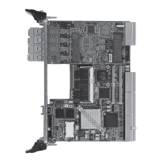
- Page 53 Switch Settings Installation Figure 5: Securing the PMC using Screws provided Installation of the PMC on IXP/CPCI-9120 is now complete. A view of the IXP/CPCI-9120 with the installed PMC is shown in Figure 6. Figure 6: IXP/CPCI-9120 with the installed PMC Note: Ensure that you cover the unused FrontPanel cutouts with filler panels.
-
Page 54: Removing Pmc
To remove the PMC from IXP/CPCI-9120 follow the steps detailed here: 1. Turn off system power. 2. Remove IXP/CPCI-9120 from the system as per the removal procedure detailed in section “Installation in a Non-Powered System”. 3. Carefully unscrew the PMC from the bottom of the IXP/CPCI-9120. -
Page 55: Ixp/Cpci-9120 Board Installation
The I provides hot-swap support and hence may be installed in or removed from XP/CPCI-9120 a powered system. This section details installation of IXP/CPCI-9120 in a non-powered sys- tem and in a powered system supporting hot-swap. Installation in a Non-Powered System... - Page 56 All manuals and user guides at all-guides.com Installation IXP/CPCI-9120 Board Installation Figure 7: Top and bottom Injector/Ejector Handles in the outward position 4. Check that the top and bottom injector/ejector handles are in the outward position as shown by arrows in Figure 7.
- Page 57 All manuals and user guides at all-guides.com IXP/CPCI-9120 Board Installation Installation Figure 8: Installing Board -- Slide Board into Chassis 6. Simultaneously move the top and bottom injector/ejector handles to the inward position. 7. Verify that the board is seated properly.
-
Page 58: Removal Procedure
Caution Never hot-swap the IXP/CPCI-9120 unless a hot-swap or high availability platform is used and the documentation of all installed boards and the system documentation explic- itly include appropriate guidelines. -
Page 59: Installation In Basic Hot Swap System
1. Ensure that the board has the desired accessories and all switches are appropriately configured. 2. Ensure that IXP/CPCI-9120 is inserted into a slot that does not have an RTB already installed. 3. Insert board into powered system by placing the top and bottom edges of the board in the card guides of the chassis as shown in Figure 8. -
Page 60: Installation In Full Hot-Swap System
1. Ensure that the board has the desired accessories and that all switches are appropri- ately configured. 2. Ensure that IXP/CPCI-9120 is inserted into a slot that does not have an RTB already installed. 3. Insert board into powered system as per the steps 3 to 8 detailed in “Installation in Basic Hot Swap System”. -
Page 61: Removal From Full Hot-Swap System
All manuals and user guides at all-guides.com IXP/CPCI-9120 Board Installation Installation Removal from Full Hot-Swap System To remove the board from a full hot-swap system, proceed as follows: 1. Press red buttons on ejector/injector handles to indicate board removal. 2. Wait until blue hot-swap LED is illuminated. -
Page 62: Controls, Indicators And Connectors
All manuals and user guides at all-guides.com Controls, Indicators and Connectors... - Page 63 All manuals and user guides at all-guides.com...
-
Page 64: Front Panel
All manuals and user guides at all-guides.com Controls, Indicators and Connectors Front Panel Front Panel An IEEE 1101.10-compliant front panel is used on the IXP/CPCI-9120. The front panels are equipped with an EMC gasket and two ejector/injector handles. The front panel accommodates the following: •... - Page 65 All manuals and user guides at all-guides.com Front Panel Controls, Indicators and Connectors Figure 10: Front Panel of IXP/CPCI-9120 see following page. Description of IO Interfaces, Switches and LEDs on Front Panel, Table 9: Description of IO Interfaces, Switches and LEDs...
-
Page 66: Leds
Reset Switch User defined Bi-color LED Hot swap status LED Power Status Bi-color LED LEDs The following indicators are provided on the front panel of the IXP/CPCI-9120: Table 10: Description of Front Panel LEDs Description Hot Swap Blue LED Hot Swap status LED. When illuminated, indicates that it is safe to extract the board from a live backplane. -
Page 67: Keys
A pinhole reset switch is provided on the front panel. Pressing this switch causes all devices on the IXP/CPCI-9120 to reset except IBMU. This reset will be active as long as the reset switch is held in the active position. -
Page 68: On-Board Connectors
All manuals and user guides at all-guides.com Controls, Indicators and Connectors Front Panel On-Board Connectors IXP/CPCI-9120 has the following on-board connectors: • CompactPCI connectors • PrPMC connectors • MSF mezanine connector • LA-1 mezzanine connector CompactPCI Connectors CompactPCI connectors J1, J2, J3, and J5 are present. -
Page 69: Prpmc Connectors
Jn4 for User I/O signals Local bus signal pins on Jn1, Jn2 and Jn3 are assigned as specified by MMSC of IEEE in Draft Standard Physical and Environmental Layers for PCI Mezzanine Cards: PMC P1386.1/Draft 2.4. Therefore, these pinouts have not been documented. IXP/CPCI-9120... -
Page 70: Msf Mezzanine Connector
Two 400-pin MEG-Array® connectors from FCI are used to connect the baseboard with the MSF mezzanine card. One connector contains all MSF, C-bus, LED signals and Power sig- nals. MDI signals, I2C, JTAG and SlowPort signals are routed through the second 400-pin connector. IXP/CPCI-9120... - Page 71 All manuals and user guides at all-guides.com Front Panel Controls, Indicators and Connectors Figure 15: MSF Mezzanine Connector Pinout (rows A-C). IXP/CPCI-9120...
- Page 72 All manuals and user guides at all-guides.com Controls, Indicators and Connectors Front Panel Figure 16: MSF Mezzanine Connector Pinout (rows D-E) IXP/CPCI-9120...
- Page 73 All manuals and user guides at all-guides.com Front Panel Controls, Indicators and Connectors Figure 17: MSF Mezzanine Connector Pinout (rows F-H) IXP/CPCI-9120...
- Page 74 All manuals and user guides at all-guides.com Controls, Indicators and Connectors Front Panel Figure 18: MSF Mezzanine Connector Pinout (rows J-K) IXP/CPCI-9120...
- Page 75 All manuals and user guides at all-guides.com Front Panel Controls, Indicators and Connectors Figure 19: MSF Mezzanine Connector Pinout (MDI, SlowPort, I2C and JTAG) rows A-C IXP/CPCI-9120...
- Page 76 All manuals and user guides at all-guides.com Controls, Indicators and Connectors Front Panel Figure 20: MSF Mezzanine Connector Pinout (MDI, SlowPort, I2C and JTAG) rows D-E IXP/CPCI-9120...
- Page 77 All manuals and user guides at all-guides.com Front Panel Controls, Indicators and Connectors Figure 21: MSF Mezzanine Connector Pinout (MDI, SlowPort, I2C and JTAG) rows F-H IXP/CPCI-9120...
-
Page 78: La-1 Mezzanine Connector
Figure 22: MSF Mezzanine Connector Pinout (MDI, SlowPort, I2C and JTAG) rows J-K Note: Rows B, D, F, H and K are Ground. LA-1 Mezzanine Connector A 200-pin MEG-Array® connector from FCI is used to connect the QDR II Channel 1 inter- face of the IXP2400 to the LA-1 mezzanine card. IXP/CPCI-9120... - Page 79 All manuals and user guides at all-guides.com Front Panel Controls, Indicators and Connectors Figure 23: LA-1 Pinout rows A-C Figure 24: LA-1 Pinout rows D-E IXP/CPCI-9120...
- Page 80 All manuals and user guides at all-guides.com Controls, Indicators and Connectors Front Panel Figure 25: LA-1 Pinout rows F-H Figure 26: LA-1 Pinout rows J-K IXP/CPCI-9120...
- Page 81 All manuals and user guides at all-guides.com Front Panel Controls, Indicators and Connectors IXP/CPCI-9120...
-
Page 82: Devices' Features And Data Paths
All manuals and user guides at all-guides.com Devices’ features and Data Paths... - Page 83 All manuals and user guides at all-guides.com...
-
Page 84: Block Diagram
To PICMG2.16 Links Figure 27: Single Slot Complex Functional Block Diagram The IXP2400 The IXP/CPCI-9120 is based on the Intel IXP2400 Network Processor (Sausalito). • Half Duplex OC-48 / 2.5 Gbps Network Processor • Integrated Intel XScale Core that operates at frequencies of 400 MHz and 600 MHz. -
Page 85: Pci Controller
1356-Ball FCBGA2 package PCI Controller The PCI Controller provides 64-bit, 66-MHz-capable PCI Rev. 2.2 interface. It is also compat- ible to 32-bit and/or 33 MHz PCI devices. The PCI interface on IXP/CPCI-9120 is clocked at 66 MHz. DDR Controller The DDR Controller contains the mechanism that allows the Xscale, microengines and PCI units to access the DDR SDRAM connected to the IXP2400. -
Page 86: Serial Port
The 82546GB provides two PICMG 2.16 links on a Packet Switching Backplane (PSB). Processor PMC The IXP/CPCI-9120 provides one VITA 32–compliant Processor PMC site on to which addi- tional I/O or processing power may be added. This site is connected to the IXP2400 via the local PCI bus. -
Page 87: Pci Bus Signaling On The Compactpci Bus
2.16 links. Programmable devices BootROM Flash The IXP/CPCI-9120 provides 4 MB of BootROM Flash. Support for up to 8 MB of BootROM Flash is provided on the IXP/CPCI-9120. User Flash An Intel StrataFlash is used to provide 16 MB of User Flash. Up to 32 MB of User Flash can be accommodated. -
Page 88: Icmb
ICMB ICMB is an RS-485-based bus used to connect the BMCs of two or more chassis. The ICMB port of IXP/CPCI-9120 is located on the RTB. Connections from the IPMI controller are routed through CompactPCI connectors to the RTB. IXP/CPCI-9120... - Page 89 All manuals and user guides at all-guides.com Block Diagram Devices’ features and Data Paths IXP/CPCI-9120...
-
Page 90: Daughter Card Details
All manuals and user guides at all-guides.com Daughter Card Details... - Page 91 All manuals and user guides at all-guides.com...
-
Page 92: Media Switch Fabric Mezzanine
CAT 3,4 and 5 cable. Some of its features are given below: • 10/100/1000BASE-T IEEE 802.3 compliant • Supports GMII, TBI, RGII, RTBI, and SGMII interfaces. • Integrated 1.25 GHz SERDES for 1000BASE-X fiber applications • CRC checker, packet counter • Packet generation • Software programmable LED modes IXP/CPCI-9120... -
Page 93: Io-920 Variants
All manuals and user guides at all-guides.com IO-920 Variants The IO-920 also houses an I/O connector through which MDI lines from the dual gigabit eth- ernet controller are brought into the IO-920. Through multiplexers and demultiplexers, signals from the on-board PHY and the baseboard Dual MAC (82546GB) can either be routed to the PSB . -
Page 94: La-1/Qdr Mezzanine
IXP2400's QDR II Ch1 interface to meet the modules operating requirements. The SPD device on the LA-1 module resides on the I2Cbus of the IXP2400. 2K Serial EEPROMs, internally organized with 32 pages of 8 bytes each, shall be used to provide board-specific information. IXP/CPCI-9120... - Page 95 All manuals and user guides at all-guides.com...
-
Page 96: Maps And Registers
All manuals and user guides at all-guides.com Maps and Registers... - Page 97 All manuals and user guides at all-guides.com...
-
Page 98: Pci Memory Map
Maps and Registers PCI memory map PCI memory map Table 11: PCI Memory Map PCI device Description IDSEL Device number 82546GB Dual LAN controller PrPMC First PCI agent of the PrPMC PrPMC Second PCI agent of the PrPMC IXP2400 IXP/CPCI-9120... -
Page 99: Slowport Map
All manuals and user guides at all-guides.com SlowPort map Table 12: SlowPort Map Device SlowPort Address Description Flash BootROM Flash C400 0000 – C5FF FFFF User Flash C400 0000 – C5FF FFFF General purpose EPLD Variant ID C600 0000 Indicates base board type. Version No. - Page 100 Routing of signals to RTB or PSB is controlled here. MAC pause address regis- C600 3050 Selection of the MAC port is done here for pause frame transmission. MAC pause control register C600 3060 Initiates the pause frame transmission in the selected ports IXP/CPCI-9120...
- Page 101 All manuals and user guides at all-guides.com Table 12: SlowPort Map Device SlowPort Address Description Interrupt Mask Register C700 000B Provides the ability to mask inter- rupts generated by the PHY and Interrupt Status Register C700 000F Provides status of interrupts issued by the PHY and MAC SlowPort addresses for the MAC are derived from the MAC offsets by multiplying the offset by 4 and adding the result to C600 4000.
-
Page 102: I2C Memory Map
I2C memory map NPU I2C memory map Table 13: NPU I2C Memory Map Device Description I2C Address Real Time Clock SO-DIMM SPD SO-DIMM on IXP/CPCI-9120 MSF EEPROM EEPROM I2C MUX Multiplexer for RTC LA-1 site LA-1 on IXP/CPCI-9120 PrPMC site... -
Page 103: Sense I2C Memory Map
All manuals and user guides at all-guides.com SENSE I2C memory map Table 14: SENSE I2C Memory Map Device Description I2C Address LM87 Voltage/Temperature sensor on IXP/CPCI-9120 BIB I2C Memory Map Table 15: BIB I2C Memory Map Device Description I2C Address 24LC128... -
Page 104: Register Details
Register Details General Purpose EPLD Variant ID Address: C600 0000 Type: Read only This register uniquely identifies the board as IXP/CPCI-9120 and also indicates the amount of on-board QDR II SSRAM installed. Table 16: Variant ID Description Access 00: 8 MB on-board QDR II SSRAM... -
Page 105: Board Revision Number
Type: Read/Write This register provides status of signals related to CompactPCI and hot swap. It also provides control of the hot swap blue LED. Table 20: CompactPCI Register Description Access 0: IXP/CPCI-9120 in System Slot 1: IXP/CPCI-9120 in Peripheral Slot... -
Page 106: Prpmc Register
EREADY IN: If Processor PMC is a non-Monarch 0: Non-monarch processor has not yet finished its initialization. 1: Non-monarch processor has completed its initialization. 0: Processor PMC is a Monarch 1: Processor PMC is a non-Monarch System specific register Address: C600 0030 IXP/CPCI-9120... -
Page 107: User Led Control Register
All manuals and user guides at all-guides.com Type: Read Only System-specific configurations are indicated here. Table 22: System Specific Register Description Access 0: PrPMC Mezzanine Card Present 1: PrPMC Mezzanine Card Absent 0: Reserved 1: Reserved 0: MSF Mezzanine Card Present 1: MSF Mezzanine Card Absent 0: LA1 Mezzanine Card Present 1: LA1 Mezzanine Card Absent... -
Page 108: Watchdog Timer Register
Table 26: Watchdog Enable and Watchdog Reset Enable Register Description Access 0: Enable watchdog Timer 1: Disable watchdog Timer Reset Value: 1 0: Enable watchdog timer Reset 1: Disable watchdog timer Reset Reset Value: 1 IXP/CPCI-9120... -
Page 109: Watchdog Time Set Register
All manuals and user guides at all-guides.com Watchdog Time Set Register Address: C600 00C0 Type: Read/Write This register provides a means to select the refresh time of the watchdog timer. Table 27: Watchdog Time Set Register Description Access 111: Refresh Time of 2 secs 110: Refresh Time of 3 secs 101: Refresh Time of 4 secs 100: Refresh Time of 5 secs... -
Page 110: Interrupt Mask Register-2
0: PMC Interrupt-C is not masked 1: PMC Interrupt-C is masked 0: PMC Interrupt-B is not masked 1: PMC Interrupt-B is masked 0: PMC Interrupt-A is not masked 1: PMC Interrupt-A is masked 0: RFU 1: RFU 0: RFU 1: RFU IXP/CPCI-9120... -
Page 111: Interrupt Mask Register-3
0: Watchdog Timer Interrupt is not masked 1: Watchdog Timer Interrupt is masked Reset value: 1 Reset value: 1 This bit must always be masked on the IXP/CPCI-9120. Interrupt Status Register-1 Address: C700 000C Type: Read Only This register provides Interrupt status. When interrupted, the NPU can interrogate the three In-... -
Page 112: Interrupt Status Register-2
1: PMC Interrupt-D is not active 0: PMC Interrupt-C is active 1: PMC Interrupt-C is not active 0: PMC Interrupt-B is active 1: PMC Interrupt-B is not active 0: PMC Interrupt-A is active: 1: PMC Interrupt-A is not active IXP/CPCI-9120... -
Page 113: Interrupt Status Register-3
All manuals and user guides at all-guides.com Table 32: Interrupt Status Register-2 Description Access Interrupt Status Register-3 Address: C700 000E Type: Read Only This register provides Interrupt status. When interrupted, the NPU can interrogate the three Interrupt status registers to determine the interrupt-source. Table 33: Interrupt Status Register-3 Description Access... -
Page 114: Mac Epld-Io-920
This register indicates the EPLD revision number. Figure 28: MAC EPLD – IO-920-Version Number Description Access EPLD Revision number for the current board Board Revision Number Address: C600 3012 Type: Read only This register indicates the board revision number. IXP/CPCI-9120... -
Page 115: Phy Reset Control Register
All manuals and user guides at all-guides.com Figure 29: Board revision Number Description Access Board Revision number for the current board PHY Reset Control Register Address: C600 3020 Type: Read/Write This register provides a means of controlling PHY operation. The PHY can be held in reset until the OS is ready to initialize the PHY. -
Page 116: Mac Pause Address Register
This bit is to be set (1) and then reset (0) once the address has been set in the MAC Pause address register. This initiates the transmission of the PAUSE FRAME. Reset value: 0 Interrupt Mask Register Address: C700 000B Type: Read/Write Interrupts generated from the PHY may be masked through this register. IXP/CPCI-9120... -
Page 117: Interrupt Status Register
All manuals and user guides at all-guides.com Table 39: Interrupt Mask Register Description Access 0: PHY Port-3 Interrupt is not masked 1: PHY Port-3 Interrupt is masked Reset value: 1 0: PHY Port-2 Interrupt is not masked 1: PHY Port-2 Interrupt is masked Reset value: 1 0: PHY Port-1 Interrupt is not masked 1: PHY Port-1 Interrupt is not active... -
Page 118: Redboot
All manuals and user guides at all-guides.com RedBoot... - Page 119 All manuals and user guides at all-guides.com...
-
Page 120: Action Plan
All manuals and user guides at all-guides.com RedBoot Action Plan Action Plan IXP/CPCI-9120... -
Page 121: Introduction
Introduction This chapter details the RedBoot firmware that runs on the IXP 2400 processor on the IXP/CPCI-9120 board. This chapter also details the commands that are supported by the firmware. The main purpose of RedBoot for IXP/CPCI-9120 is to boot VxWorks, Diagnostics, and Linux. -
Page 122: Building Images
7. Add the directory H-i686-pc-linux-gnulibc2.1/bin/ to the PATH variable. 8. In the SOURCES directory, make the files RUNIT.sh, packages/swapbytes_x86-linux and ecosconfig files executable using chmod command. 9. Execute the RUNIT.sh script. The Binaries will be created in the build/install/bin/ directory. IXP/CPCI-9120... -
Page 123: Loading Images From Redboot
0xC4100000 RedBoot> fis create diag -b 0x400000 -f 0xc4100000 -l 0x100000 -r 0x400000 -e 0x400000 4. Execute fis load diag command to load it to RAM RedBoot>fis load diag 5. Execute go command to execute diag. RedBoot> go 0x400000 IXP/CPCI-9120... -
Page 124: Redboot Commands
This allows the ping command to override its local network address. While -i <local IP> this is not recommended procedure, it can help diagnose some situations, for example where BOOTP is not working properly. The address of the other device to contact. -h <host IP> IXP/CPCI-9120... - Page 125 0x00000150: 0000 0000 0000 0000 0000 0000 0000 0000 |....| 0x00000160: 0000 0000 0000 0000 0000 0000 0000 0000 |....| 0x00000170: 0000 0000 0000 0000 0000 0000 0000 0000 |....| Reset YNTAX reset DESCRIPTION This command resets the system. RedBoot>reset IXP/CPCI-9120...
- Page 126 This command detects and displays all I2C devices. RedBoot> i2cdetect Detecting I2C devices..I2C MUX is present PrPMC is not present RTB is present LA-1 MEZZANINE is not present MSF MEZZANINE is present SO-DIMM-SPD is present RTC is present RedBoot> IXP/CPCI-9120...
- Page 127 [address] DESCRIPTION This command reads the value of the byte present at [address] RedBoot>inb 0xc6000003 RedBoot> Read dword YNTAX inl [address] DESCRIPTION This command reads the value of the long word at [address]. inl 0xc4000000 RedBoot> 0xfefefefe RedBoot> IXP/CPCI-9120...
- Page 128 Completion Code: 0x0 0x81 0x99 0x2b 0x48 RedBoot> Write Byte YNTAX outb [address] [value] DESCRIPTION This command writes value to byte address. outb 0xc6000000 0x0 RedBoot> Write dword YNTAX outl [address] [value] DESCRIPTION Write value to dword address RedBoot>outl 0xc6000003 0x0 IXP/CPCI-9120...
- Page 129 <reg>] [-v <data>] DESCRIPTION This command writes data to the PCI Configuration Register for the specified values of the bus number, device number, function and the register number. RedBoot> pci_config_write -b 0 -d 2 -f 0 -r 2 -v 12298086 RedBoot> IXP/CPCI-9120...
- Page 130 ... Bus = 0, Dev = 2, Fun = 0, Vendor = 8086, Device = 1229 ... Bus = 0, Dev = 6, Fun = 0, Vendor = 8086, Device = 9001 RedBoot> Program MAC Address YNTAX prog [id1] [id2] [id3] [id4] [id5] [id6] IXP/CPCI-9120...
- Page 131 Version Information YNTAX version DESCRIPTION This command displays RedBoot version information. RedBoot> version Platform: CPCI-9120 (XScale) BootMonitor Version 1.0 SDRAM(256M): 0x00000000 - 0x10000000, 0x00200000 - 0x0ffdf000 available SRAM Channel 0(8M): 0x80000000 - 0x80800000 SRAM Channel 1(8M): 0x90000000 - 0x90800000 IXP/CPCI-9120...
- Page 132 YNTAX 82546_backplane DESCRIPTION This command is used to have control plane connectivity to the back plane. RedBoot> 82546_backplane RedBoot> ixf_backplane YNTAX ixf_backplane DESCRIPTION This command is used to have data plane connectivity to the back plane. RedBoot> ixf_backplane RedBoot> IXP/CPCI-9120...
-
Page 133: Download Process
Used explicitly to name a host computer to contact for the download data. This works in TFTP mode only. RedBoot> load redboot.bin -b 0x400000 Note: In this example, the file has been loaded into the RAM address redboot.bin 0x400000. IXP/CPCI-9120... -
Page 134: Flash Image System (Fis)
Entry point RedBoot 0xC4000000 0x00000000 0x00040000 0x00000000 System Log 0xC43A0000 0xC43A0000 0x00020000 0x00000000 RedBoot config 0xC43DF000 0xC43DF000 0x00001000 0x00000000 FIS directory 0xC43E0000 0xC43E0000 0x00020000 0x00000000 diag1 0xC4100000 0x00300000 0x00100000 0x00300000 vxRag 0xC4200000 0xC4200000 0x00100000 0x00000000 redboot 0xC4100000 0x00300000 0x00100000 0x00000000 IXP/CPCI-9120... -
Page 135: Arguments
: The length of the actual data to be written to flash. If not present then the image length (- 1) value is assumed. If the value given by is less than -1, the remainder of the image in flash will be left in an erased state. IXP/CPCI-9120... -
Page 136: Arguments
: Specify the location in memory to which the file should be loaded. Executable images normally load at the location to which the file was linked. This option allows the file to be loaded to a specific memory location, possibly overriding any assumed location. IXP/CPCI-9120... - Page 137 This command is used to erase a portion of flash memory forcibly. There is no cross-checking to ensure that the area being erased does not correspond to a loaded image. RedBoot> fis erase -f 0xC4040000 -l 0x20000 ... Erase from 0xC4040000-0xC4060000: . IXP/CPCI-9120...
- Page 138 Default server IP address: 10.208.33.50 Network debug: false Default network device: i82559_fe0 RedBoot> RedBoot> fconfig -i Initialize non-volatile configuration - are you sure (y/n)? y Run script at boot: false Use BOOTP for network configuration: true Network debug: false Default network device: i82546_gb0 IXP/CPCI-9120...
- Page 139 Update RedBoot non-volatile configuration - are you sure (y/n)? ... Unlock from 0xc43c0000-0xc43e0000: ..Erase from 0xc43c0000-0xc43e0000: ..Program from 0x00059d80-0x0005ad80 at 0xc43df000: ..Lock from 0xc43c0000-0xc43e0000: . RedBoot> RedBoot> fconfig bootp_master_ip 10.208.33.133 bootp_master_ip: 10.208.33.99 Setting to 10.208.33.133 IXP/CPCI-9120...
- Page 140 Update RedBoot non-volatile configuration - are you sure (y/n)? ... Unlock from 0xc43c0000-0xc43e0000: ..Erase from 0xc43c0000-0xc43e0000: ..Program from 0x00059d80-0x0005ad80 at 0xc43df000: ..Lock from 0xc43c0000-0xc43e0000: . RedBoot> Note: Provide IP address as per the available network configuration. IXP/CPCI-9120...
-
Page 141: Executing Programs From Redboot
This mode would typically be used in startup Ctrl+C scripts. - Execute a Linux kernel image exec Arguments [-w timeout] [-b <load addr> [-l <length]] [-r <ramdisk addr> [-s <ramdisk length>]] [-c "kernel command line"] [<entry_point>] [-p <params address>] IXP/CPCI-9120... - Page 142 All manuals and user guides at all-guides.com RedBoot Executing Programs from RedBoot IXP/CPCI-9120...
- Page 143 All manuals and user guides at all-guides.com Executing Programs from RedBoot RedBoot IXP/CPCI-9120...
-
Page 144: Diagnostics
All manuals and user guides at all-guides.com Diagnostics... - Page 145 All manuals and user guides at all-guides.com...
-
Page 146: Introduction
All manuals and user guides at all-guides.com Diagnostics Introduction Introduction Diagnostics allows detailed testing of various hardware interfaces and modules on the IXP/CPCI-9120. The IXP/CPCI-9120 boards are shipped with RedBoot and Diagnostics images in the boot flash. Requirements • Console or Windows-based PC with serial port. -
Page 147: Configuring The Platform
When specified without , it displays the contents of the last address when addr size the command was issued. Listed below are the different Board Diagnostics commands for IXP/CPCI-9120: t/test t/test ESCRIPTION Displays a list of test commands within the diagnostics image. - Page 148 Enables test flags. Causes given device to be included or excluded from tests in the test all command. YNTAX tf <test_type_ID> <status> ARAMETERS test identifier. Can be any of the following: test_type_id – 0 - SRAM – 1 - SDRAM – 2 - UENG – 3 - TIMERS – 4 - PCI IXP/CPCI-9120...
- Page 149 Example: p 800000 80 pb 500000 pw 300000 pd 000 ESCRIPTION Interactively changes the contents of a specified memory address. YNTAX c <addr> ARAMETERS memory address that will change addr Example: c 1000000 cb 210000 cw 300000 cd 500000 IXP/CPCI-9120...
- Page 150 - address in memory where the block ends high • - value that will be copied to every memory cell in the specified block Example: fill 800000 800100 41 ESCRIPTION Reads (r) or writes (w) a byte (b), word (w) or dword (d) from/to memory. IXP/CPCI-9120...
- Page 151 — 1 - perform a read or write on a loop until a key is pressed • - data to write to the memory address data • - do not trace any information on the console silent – 0- display information on the console – 1- run in silent mode IXP/CPCI-9120...
- Page 152 - data to write to the memory address data Example: cfgrb 1 0 0 ESCRIPTION Read all/read/write the MAC registers. Note: MAC is IXF1104 in IO-920 YNTAX mac[r/ra/w] Example: macra macr macw ESCRIPTION Read all/write the PHY connected to the MAC through the RGMII IXP/CPCI-9120...
- Page 153 <slave_addr> <offset_addr> <data> ARAMETERS • - address of the I2C device on the bus slave_addr • - memory address inside the I2C device offset_addr • - hexadecimal string to write to I2C device memory data Example: i2write a4 30 123456789 IXP/CPCI-9120...
- Page 154 Allows a test script to be written and stored in flash and run. Note: To finish the script, just enter a null string. YNTAX createscript Example: createscript viewscript ESCRIPTION Displays the test script stored in the flash. YNTAX viewscript Example: viewScript IXP/CPCI-9120...
- Page 155 - unique test – - address bus test – - pattern test (<x:data> is required) – - incremental test – - ECC test (only applicable to DRAM) – - March B test – - Random Read test – - all tests IXP/CPCI-9120...
- Page 156 Performs XScale scratchpad and core component tests. The tests cover IRQs and internal scratch memory tests. YNTAX t xscale <option> ARAMETERS - indicates a test option to perform. Can be set as follows: option • - XScale interrupt test • s - XScale scratchpad test IXP/CPCI-9120...
- Page 157 Note: Watchdog Timer test causes the system to reset. YNTAX t timers <option> ARAMETERS indicates a test option to perform. Can be set as follows: option- • Generic Timer test • Watchdog timer test • all tests • help IXP/CPCI-9120...
- Page 158 – all uEngine tests – help • specifies the uEngine ID to test. 0-3 and 16-19. Entering 99 will test all microengine - uEngines. • specifies how many times the test is performed (default is 1) loop - IXP/CPCI-9120...
- Page 159 ESCRIPTION Performs epld Register tests. YNTAX t epld <option> ARAMETERS • indicates the test to perform. Can be set as follows: option - – slowport register default test – slowport register write-read test – all slowport tests IXP/CPCI-9120...
- Page 160 – help Example: t nic p t dma ESCRIPTION Performs the PCI DMA tests on both the channels YNTAX t dma Example: t dma t ipmi ESCRIPTION Detects the presence of IPMI controller. YNTAX t ipmi Example: t ipmi IXP/CPCI-9120...
- Page 161 All manuals and user guides at all-guides.com Introduction Diagnostics t spi3 ESCRIPTION Performs the spi3 interface test between IXDP2400 and IXF1104. YNTAX t spi3 Example: t spi3 IXP/CPCI-9120...
-
Page 162: Troubleshooting
All manuals and user guides at all-guides.com Troubleshooting... - Page 163 All manuals and user guides at all-guides.com...
- Page 164 RTB not defined for the used Install RTB defined for the used peripheral or peripheral or system board system board. Rear panel reset does not Function is disabled Ensure that position 1 of SW2 on the RTB is work OFF. (Refer to Table 7.) IXP/CPCI-9120...
- Page 165 Improve cooling inside the system if necessary. Ensure that other envi- ronmental requirements, such as moisture or altitude, are satisfied. Drivers are missing, faulty or Reinstall appropriate drivers. do not match hardware. Board defect Replace board IXP/CPCI-9120...
- Page 166 I2C bus ............86 IBMU ............86 Injector/ejector levers ......55, 58 Installation Accessories ...........43 CPCI-9120 ..........54 IXP/CPCI-9120/256/8-8/16/4GBE-T/R / CPCI-9120, hot swap ......58 ..........43 ......54 non-powered system ..........42 Unpack Kit ..........50 Installing PMC ............47 IO-920 .............51...
- Page 167 Interrupt Mask Register-3 110 Interrupt Status Register-1 110 Interrupt Status Register-2 111 Interrupt Status Register-3 112 PrPMC register 105 System specific register 105 User Flash Select 104 User LED Control register 106 Variant ID 103 Version Number 103 Watchdog Timer Register 107 IXP/CPCI-9120...
- Page 168 All manuals and user guides at all-guides.com...