Table of Contents
Advertisement
Quick Links
Air-Conditioners For Building Application
TECHNICAL & SERVICE MANUAL
Series PFFY
<Indoor unit>
PFFY-P20VLEM-E,PFFY-P20VLRM-E
Models
PFFY-P25VLEM-E,PFFY-P25VLRM-E
PFFY-P32VLEM-E,PFFY-P32VLRM-E
PFFY-P40VLEM-E,PFFY-P40VLRM-E
PFFY-P50VLEM-E,PFFY-P50VLRM-E
PFFY-P63VLEM-E,PFFY-P63VLRM-E
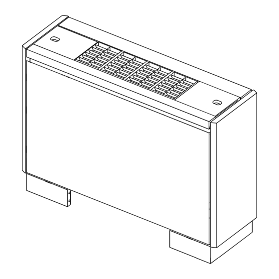
Exposed type
Floor Standing Type
Concealed type
For use with the R410A & R407C & R22
2004
CONTENTS
SAFETY PRECAUTIONS ·························1
1. FEATURES ···········································3
2. PART NAMES AND FUNCTIONS ········4
3. SPECIFICATION ···································6
4. OUTLINES AND DIMENSIONS············8
5. WIRING DIAGRAM ·····························10
7. TROUBLE SHOOTING ·······················12
8. DISASSEMBLY PROCEDURE ··········· 17
····
11
Advertisement
Table of Contents

Related Manuals for Mitsubishi Electric CITY MULTI PFFY-P20VLEM-E


Summary of Contents for Mitsubishi Electric CITY MULTI PFFY-P20VLEM-E
-
Page 1: Table Of Contents
2004 Air-Conditioners For Building Application TECHNICAL & SERVICE MANUAL Floor Standing Type Series PFFY <Indoor unit> PFFY-P20VLEM-E,PFFY-P20VLRM-E Models PFFY-P25VLEM-E,PFFY-P25VLRM-E PFFY-P32VLEM-E,PFFY-P32VLRM-E PFFY-P40VLEM-E,PFFY-P40VLRM-E PFFY-P50VLEM-E,PFFY-P50VLRM-E PFFY-P63VLEM-E,PFFY-P63VLRM-E CONTENTS SAFETY PRECAUTIONS ·························1 1. FEATURES ···········································3 2. PART NAMES AND FUNCTIONS ········4 3. SPECIFICATION ···································6 4. OUTLINES AND DIMENSIONS············8 5. -
Page 2: Safety Precautions
- Inadequate strength may cause the unit to fall down, resulting in is shorted and operated forcibly, or parts other than those specified injuries. by Mitsubishi Electric are used, fire or explosion may result. • Use the specified cables for wiring. Make the connections se- curely so that the outside force of the cable is not applied to the •... - Page 3 Precautions for devices that use R410A or R407C refrigerant Caution: • Do not use the existing refrigerant piping. - The old refrigerant and refrigerator oil in the existing piping con- tains a large amount of chlorine which may cause the refrigerator oil of the new unit to deteriorate.
-
Page 4: Features
FEATURES Series PFFY Floor Standing Type Exposed type Concealed type Cooling capacity/Heating capacity Models 2.2 / 2.5 PFFY-P20VLEM-E,PFFY-P20VLRM-E 2.8 / 3.2 PFFY-P25VLEM-E,PFFY-P25VLRM-E PFFY-P32VLEM-E,PFFY-P32VLRM-E 3.6 / 4.0 PFFY-P40VLEM-E,PFFY-P40VLRM-E 4.5 / 5.0 PFFY-P50VLEM-E,PFFY-P50VLRM-E 5.6 / 6.3 PFFY-P63VLEM-E,PFFY-P63VLRM-E 7.1 / 8.0... -
Page 5: Part Names And Functions
PART NAMES AND FUNCTIONS Indoor (Main) Unit Air outlet Air outlet Air inlet Air inlet Exposed type Concealed type Remote controller [PAR-20MAA] Once the controls are set, the same operation mode can be repeated by simply pressing the ON/OFF button. [Operation uttons] CENTRALLY CONTROLLED... - Page 6 [Display] CENTRALLY CONTROLLED 1Hr. ON OFF ˚C CLOCK CHECK FILTER CHECK MODE ˚C TEST RUN STAND BY ERROR CODE FUNCTION NOT AVAILABLE DEFROST TEMP. ON/OFF I KL J Current time/Timer Centralized control Timer ON Abnormality occurs Operation mode: COOL, DRY, AUTO, FAN, HEAT...
-
Page 7: Specification
SPECIFICATION 3-1. Specification PFFY-P20 PFFY-P25 PFFY-P32 PFFY-P40 PFFY-P50 PFFY-P63 Model Item VLEM-E VLEM-E VLEM-E VLEM-E VLEM-E VLEM-E 220-240 208-230 220-240 208-230 220-240 208-230 220-240 208-230 220-240 208-230 220-240 208-230 Voltage Power source Frequency Note:1 Cooling capacity Heating capacity Note:1 0.065 0.075 0.085 0.09... - Page 8 3-2. Electrical parts specification Model PFFY-P20 PFFY-P25 PFFY-P32 PFFY-P40 PFFY-P50 PFFY-P63 Symbol VLEM-E VLEM-E VLEM-E VLEM-E VLEM-E VLEM-E Parts VLRM-E VLRM-E VLRM-E VLRM-E VLRM-E VLRM-E name Tranrsformer (Primary) 50/60Hz 220-240V (Secondary) (18.4V 1.7A) Room temperature TH21 Resistance 0˚C/15kΩ,10˚C/9.6kΩ,20˚C/6.3kΩ,25˚C/5.4kΩ,30˚C/4.3kΩ,40˚C/3.0kΩ thermistor Liquid pipe TH22 Resistance 0˚C/15kΩ,10˚C/9.6kΩ,20˚C/6.3kΩ,25˚C/5.4kΩ,30˚C/4.3kΩ,40˚C/3.0kΩ...
-
Page 9: Outlines And Dimensions
OUTLINES AND DIMENSIONS PFFY-P20·25·32·40·50·63VLEM-E Unit:mm... - Page 10 PFFY-P20·25·32·40·50·63VLRM-E Unit:mm...
-
Page 11: Wiring Diagram
WIRING DIAGRAM... -
Page 12: Refrigerant System Diagram
REFRIGERANT SYSTEM DIAGRAM Gas pipe thermistor TH23 Gas pipe Liquid pipe thermistor TH22 Flare connection Heat exchanger Linear expansion valve Strainer (#100mesh) Strainer (#100mesh) Room temparature thermistor TH21 PFFY-P20,25,32,40VLEM-E PFFY-P50VLEM-E PFFY-P63VLEM-E PFFY-P20,25,32,40VLRM-E PFFY-P50VLRM-E PFFY-P63VLRM-E Item ø 12.7 <1/2F> (R410A) Gas pipe ø... -
Page 13: Trouble Shooting
TROUBLE SHOOTING 7-1. How to check the parts Parts name Check points Room temparature Disconnect the connector, then measure the resistance using a tester. thermistor (TH21) (Surrounding temperature 10°C~30°C) Liquid pipe thermistor (TH22) Normal Abnormal Gas pipe thermistor (Refer to the thermistor characteristic graph (TH23) 4.3kΩ... - Page 14 <Thermistor Characteristic graph> < Thermistor for lower temperature > Room temparature thermistor(TH21) Thermistor for Liquid pipe thermistor(TH22) lower temperature Gas pipe temparature thermistor(TH23) Drain sensor(DS) =15kΩ ± 3% Thermistor R Fixed number of B=3480kΩ ± 2% Rt=15exp { 3480( 273+t 0˚C 15kΩ...
- Page 15 <Output pulse signal and the valve operation> Output Output : 1 ¡ 2 ¡ 3 ¡ 4 ¡ 1 (Phase) Closing a valve Opening a valve : 4 ¡ 3 ¡ 2 ¡ 1 ¡ 4 ø1 The output pulse shifts in above order. ø2 ✻...
- Page 16 7-2. Setting of address switch Make sure that power source is turning off. Indoor unit control board SW 3 S W 4 < At delivery (All models)> S W 4 < At delivery (All models)> 1 2 3 4 5 6 7 8 9 10 0 1 2 3 4 5 6 7 8 9 9 10...
- Page 17 7-3. Function of Dip-switch Operation by switch Switch Pole Function Remarks Thermistor<Intake temperature Indoor unit Built-in remote controller Address board detection>position Filter crogging detection Provided Not provided <At delivery> Filter life 2,500hr 100hr 1 2 3 4 5 6 7 8 9 10 Air intake Effective Not effective...
-
Page 18: Disassembly Procedure
DISASSEMBLY PROCEDURE 8-1 CONTROL BOX (Exposed type PFFY-P·VLEM) Be careful removing heavy parts. OPERATING PROCEDURE PHOTOS 1.Removing the front panel (A) (1)Remove the fixing screws(two) of the front panel(A).(Fig.1) (2)Hold the bottom of the front panel with your hands,and gently lift it. The front panel should fall down forward.(Fig.2) 2.Removing the control box cover (B) (1)Remove the fixing screws(two) of the cover(B) and... - Page 19 8-2 THERMISTOR (Gas and liquid piping temperature detection) Be careful removing heavy parts. OPERATING PROCEDURE OPERATING PROCEDURE PHOTOS PHOTOS 1.Removing the side casing (1)Open the control panel cover(A), remove the fixing screws(two) of the securing cover. (Fig. 1) (2)Pull up the side casing(B). (Fig. 2) Fig.1 Fig.2 2.Removing the thermistor...
- Page 20 8-3 THERMISTOR (Intake air temperature detection) Be careful removing heavy parts. OPERATING PROCEDURE PHOTOS 1.Removing the thermistor (1)Remove the thermistor under the control box. Thermistor Fig.1 8-4 DRAINPAN OPERATING PROCEDURE PHOTOS 1.Removing the drainpan (1)Remove the fixing screw of the side frame by the control box.
- Page 21 8-5 FAN and FAN MOTOR Be careful removing heavy parts. OPERATING PROCEDURE PHOTOS 1.Sliding the fan section (Fig.1) (1)Remove the fixing screws(two) (a). (2)Slide the fan section in direction of the arrow ➀. 2.Removing the fan motor (Fig.2) (1)Remove the fixing screws (two)(b) of the fan cas- ing(A).
- Page 22 8-6 HEAT EXCHANGER Be careful removing heavy parts. OPERATING PROCEDURE PHOTOS 1.Removing the casing (1)Remove the fixing screws(six) and remove the casing. (Fig. 1) 2.Removing the cover1,2 with procedure 8-2 (Fig. 2) 3.Removing the Heat exchanger (1)Remove the fixing screws(four) and remove the heat exchanger support.
- Page 23 8-7 CASING (Concealed type PFFY-P·VLRM) Be careful removing heavy parts. OPERATING PROCEDURE PHOTOS 1.Removing the casing ass’y (1)Remove the fixing screws (nine) of the plate(A) and remove the plate. (Fig. 1) 2.Removing the air diffuser ass’y (1)Remove the fixing screws (eight) of the air diffuser ass’y(B) and remove it.
- Page 24 HEAD OFFICE: MITSUBISHI DENKI BLDG., 2-2-3, MARUNOUCHI, CHIYODA-KU, TOKYO 100-8310, JAPAN Issued in June 2004 MEE04K244 New publication, effective June 2004 Printed in Japan Specifications subject to change without notice...
- Page 25 Related Links Model Number: PFFY-P63VLEM-E PFFY-P20-63VL(E)(R)M(M)-E Declaration of Conformity PFFY-P20-63VL(E)(R)M(M)-E Instruction Book (WT04883X05) PFFY-P20-63VL(E)(R)M-E Installation Manual (WT04208X05) PFFY-P20-63VL(E)(R)M-E Parts Catalogue (BWE0405G) PFFY-P20-63VL(E)(R)M-E Service Manual (MEE04K244) PFFY-P20-63VLEM-E Product Information Sheet PFFY-P20-63VLEM_Parts_Catalog_(BWE0405C) PFFY-P20-63VLEM_Declaration_of_Conformity_(EU-04002A_2) PFFY-P20-63VLEM_Installation_Manual_(WT04208X02) PFFY-P20-63VLEM_Instruction_Book_(WT04187X03) PFFY-P20-63VLEM_Service_Manual_(MEE04K244)