
Related Manuals for Sony RCP-730


Summary of Contents for Sony RCP-730
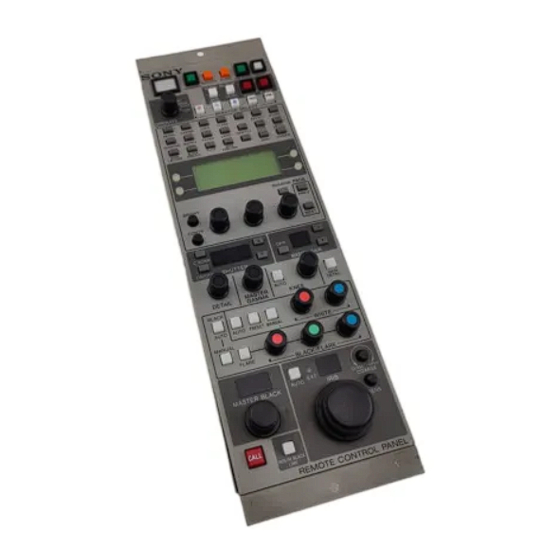
- Page 1 REMOTE CONTROL PANEL RCP-730 RCP-731 MAINTENANCE MANUAL 1st Edition Serial No. 15001 and Higher...
- Page 2 ! WARNING This manual is intended for qualified service personnel only. To reduce the risk of electric shock, fire or injury, do not perform any servicing other than that contained in the operating instructions unless you are qualified to do so. Refer all servicing to qualified service personnel.
-
Page 3: Table Of Contents
Maintenance Mode ................2-1 (E) 2-2. Removal of Bottom Assembly ..............2-2 (E) 2-3. Replacement of Master Black Control (RCP-730) ....... 2-3 (E) 2-4. Removal of J-Control panel Assembly (RCP-730) ....... 2-5 (E) 2-5. Replacement of D-Control panel Assembly (RCP-731) ....... 2-6 (E) 2-6. - Page 4 Location of Printed Circuit Boards ............7-1 MPU-79 ....................7-2 CN-1453 ....................7-4 SW-893 ....................7-7 SW-894 ....................7-13 LED-265 ....................7-19 LED-266 ....................7-19 LED-267 ....................7-20 LED-269 ....................7-20 LED-270 ....................7-21 LED-298 ....................7-21 2 (E) RCP-730 RCP-731...
-
Page 5: Manual Structure
Manual Structure Purpose of this manual This manual is the maintenance manual for Remote Control Panel RCP-730, RCP-731. This manual describes the information items necessary when the unit is supplied and installed, items on maintenance, and items that premise the service based on the components parts such as schematic diagrams, board layouts and spare parts list, assuming use of system and service engineers. -
Page 7: Installation
1-1. Connectors and Cables 1-1-1. Connector Input/Output Signals The main connector input/output signals are as follows; REMOTE PREVIEW (6-pin, FEMALE) CCU/CNU (8-pin, FEMALE) (EXTERNAL VIEW) (EXTERNAL VIEW) RCP-730 Signal Specification Signal Specification Non-connection TX (+) RCP SERIAL DATA 30 V dc max 0.1 mA... -
Page 8: Connection Connector
(6P, FEMALE) CCU/CNU (8P, FEMALE) 1-766-848-11 PULG, 8P MALE or CABLE ASSEMBLY CCA-5-3, CCA-5-10 1-1-3. Cable Wiring CCA-5 CABLE (wiring diagram) Black White Orange White Brown White Brown Brown 8P CONNECTOR(MALE) 8P CONNECTOR(MALE) (WIRING SIDE) (WIRING SIDE) 1-2 (E) RCP-730 RCP-731... -
Page 9: Installation
1-2-2. Installation Space Provide a space of 7cm or more behind the connector panel. (This prevents cable breakdown.) 1-2-3. Installtion to Console RCP-730/731 can be installed into the control console using the brackets which are supplied with product. 1-3 (E) RCP-730... -
Page 10: Outside Dimensions
1-2. Installation 1-2-4. Outside Dimensions RCP-730 2-ø5 HOLES CALL Unit : mm RCP-731 2-ø5 HOLES Unit : mm 1-4 (E) RCP-730 RCP-731... -
Page 11: Functions Of Internal Switches
ISR : Interactive status Reporting command mode Be sure to set S7 and S8 to the same mode. Factory-setting is “CMD”. (REM MODE-2) (REM MODE-1) (RESET) IC10 S1 S2 S3 (BUZZER ON/OFF) MPU-79 BOARD ( A SIDE ) 1-5 (E) RCP-730 RCP-731... -
Page 12: Instance Of System Configuration
COAX CABLE ENG/EFP LENS ELECTRONIC VIEWFINDER BVF-55/55CE COLOR VIDEO CAMERA BVP-750/750P 1.5" VF CCD UNIT OHB-750/750P OHB-750W/750WP TRIAX CABLE (*2) ENG/EFP LENS *2: TRIAX CABLE LENGTH Diameter Maximun length 8.5 mm 1000 mm 14.5 mm 2000 mm 1-6 (E) RCP-730 RCP-731... - Page 13 1-4. Instance of System Configuration REMOTE CONTROL PANEL RCP-720 RCP-721 RCP-740 RCP-741 RCP-730 RCP-731 REMOTE CONTROL PANEL CCA-5 CABLE RCP-700 RCP-701 (*1) CCA-5 CABLE (*1) CAMERA CONTROL UNIT CCA-5 CABLE CCA-5 CABLE CCU-700/700P (*1) (*1) CAMERA COMMAND NETWORK UNIT CNU-700/500...
-
Page 15: Service Overview
Section 2 Service Overview 2-1. Maintenance Mode Press these buttons simultaneously. The RCP-730 and RCP-731 are provided with LCD maintenance mode. Press a paint item select button (WHITE) while pressing LOCK and PARA simultaneously to select the mainte- nance mode. -
Page 16: Removal Of Bottom Assembly
A to disengage the hook at section . To replace components on the board, remove the bottom assembly and replace them using this procedure. Panel assembly 1+B3 x 8 Bottom assembly 2-2 (E) RCP-730 RCP-731... -
Page 17: Replacement Of Master Black Control (Rcp-730)
2-3. Replacement of Master Black Control (RCP-730) 2-3. Replacement of Master Black Control (RCP-730) Disconnecting 1. Remove the screw to remove cover tube. 3. Remove the nut securing the control and remove the two screws. VR fixed tube will be removed. - Page 18 2-3. Replacement of Master Black Control (RCP-730) Connecting 5. Solder the harness to the master black control. 1. Orange 2. Red 3. Yellow 6. Install the master black control by reversing the preceding procedures 1 to 3. 2-4 (E) RCP-730...
-
Page 19: Removal Of J-Control Panel Assembly (Rcp-730)
2-4. Removal of J-Control panel Assembly (RCP-730) 2-4. Removal of J-Control panel Assembly (RCP-730) 1. Remove the master black control referring to section 2-3 . 2. Loosen the two screws and remove the lever fixed tube. 3. Remove the three knobs. -
Page 20: Replacement Of D-Control Panel Assembly (Rcp-731)
3. Remove the four screws to remove the two rack brackets and D-Control panel assembly. IRIS Knob Set screw Knobs 3 x 3 +B3 x 5 Bearing Iris Knob gage Rack bracket Bearing Rack bracket D-Control panel assembly +B3 x 5 Shaft iris control 2-6 (E) RCP-730 RCP-731... - Page 21 Install the IRIS gage while pushing the friction lever at the back of the panel in the direction of the arrow using a screwdriver. 6. Fix the IRIS Knob with the setscrew. IRIS Knob Setscrew 3 x 3 Bearing IRIS gage Bearing Friction lever Driver 2-7 (E) RCP-730 RCP-731...
-
Page 22: Adjustment Sfter Iris Control Replacement (Rcp-730)
2-6. Adjustment sfter IRIS Control Replacement (RCP-730) 2-6. Adjustment sfter IRIS Control Replacement (RCP-730) After replacement of the control of the IRIS lever, adjust 3. Move joystick lever fully in the direction of IRIS gear (A) and IRIS gear (B) so that they mesh proper- the arrow A. -
Page 23: Connecting/Disconnecting Flexible Card Wire
Push down the *marked portions, then slide it in the direction of the arrow (C) to lock. Conductive surface 1. Do not insert the flexible card wire on a slant. 2. Do not short the terminals of the flexible card wire. 2-9 (E) RCP-730 RCP-731... - Page 24 SW board CN19 Conductive surface(Silver) Conductive surface (Silver) MPU(CN2) MPU(CN5) Insulated surface (Blue) Insulated surface (Blue) SW (CN15) Unit : mm Unit : mm . MPU-79 board CN3 SW board CN1 MPU(CN3) Insulated surface (Blue) Unit : mm 2-10 (E) RCP-730 RCP-731...
-
Page 25: Notes On Service
Therefore, specified parts should be used in the case of (REM MODE-1) replacement. 2. Standardization of Parts Some repair parts supplied Sony differ from those used for the unit. These are because of parts common- ality and improvement. (RESET) IC10 Parts list has the present standardized repair parts. - Page 27 Section 3 Spare Parts Index 3-1. Exploded Views ........... 3-2 For RCP-730 ............ 3-2 For RCP-731 ........... 3-4 3-2. Electrical Parts List ..........3-8 3-3. Supplied Accessories .......... 3-22 RCP-730 RCP-731...
-
Page 28: Exploded Views
3-1. Exploded Views RCP-730 Precision P2.6 x 6 B3 x 5 SET SCT, HEX2.6 x 3 SW2.6 SET SCT, HEX2.6 x 3 PWH3 x 6 B3 x 5 SET SCT, HEX2.6 x 3 P2.6 x 6 P2.6 x 6 PWH3 x 6... - Page 29 3-687-159-01 o LED SPACER 3-710-803-03 o HOLDER, DIA. 5-9 LED 1-663-402-11 o PRINTED CIRCUIT BOARD, LED-269 3-716-370-01 o SPACER 1-663-403-11 o PRINTED CIRCUIT BOARD, LED-270 1-663-404-11 o PRINTED CIRCUIT BOARD, CN-1453 4-861-741-01 s CUSHION 3-605-853-01 o SHEET,INSULATING 3-605-855-01 o BOTTOM CHASSIS RCP-730 RCP-731...
- Page 30 2-141-006-01 o GUARD (SQUARE 6), SWITCH 3-681-097-02 o IRIS KNOB 3-681-098-01 o DIAL POINTER 2-249-353-00 s COVER, LAMP 3-681-382-01 o FRICTION LEVER 3-178-147-02 s KNOB, VOLUME 3-178-213-21 s SCREW +B 3X10 3-681-389-01 o SWITCH GUARD 3-685-649-02 o RACK BRACKET 3-738-602-01 o SPACER (3X6) RCP-730 RCP-731...
- Page 31 1-574-161-11 s CABLE, FLAT (1MM PITCH) 25P 3-687-159-01 o LED SPACER 1-663-395-11 o PRINTED CIRCUIT BOARD, LED-265 3-710-803-03 o HOLDER, DIA. 5-9 LED 1-663-396-11 o PRINTED CIRCUIT BOARD, LED-266 3-716-370-01 o SPACER 1-663-397-11 o PRINTED CIRCUIT BOARD, LED-267 RCP-730 RCP-731...
- Page 32 RCP-730 RCP-731 Part No. SP Description Part No. SP Description 3-708-895-01 s CAP 3-708-933-11 s CAP “CALL”(RED) 3-708-895-01 s CAP 3-708-934-01 s CAP (GREEN) 3-708-933-11 s CAP “CALL”(RED) 3-708-937-01 s CAP “ON” 3-708-934-01 s CAP (GREEN) 3-708-937-11 s CAP “SEQ”...
- Page 33 7-671-156-01 s BALL, STAINLESS 7-682-546-04 s SCREW +B 3X5 7-682-548-04 s SCREW +B 3X8 7-682-648-09 s SCREW +PS 3X8 7-682-903-01 s SCREW +PWH 3X5 7-682-903-11 s SCREW +PWH 3X6 7-682-947-01 s SCREW +PSW 3X6 7-685-133-19 s SCREW +P 2.6X6 TYPE2 RCP-730 RCP-731...
-
Page 34: Electrical Parts List
3-2. Electrical Parts List ------------- ------------------------- CN-1453 BOARD LED-269 BOARD FOR RCP-730 ------------- ------------------------- Ref. No. Ref. No. or Q'ty Part No. SP Description or Q'ty Part No. SP Description 1-663-404-11 o PRINTED CIRCUIT BOARD, CN-1453 1-663-402-11 o PRINTED CIRCUIT BOARD, LED-269... - Page 35 1-506-483-11 o PIN, CONNECTOR 4P 1-128-391-11 s ELECT 330uF 20% 6.3V 1-506-482-11 o PIN, CONNECTOR 3P 1-135-179-21 s TANTAL 2.2uF 10% 16V 8-719-210-39 s DIODE EC10QS-04 1-135-179-21 s TANTAL 2.2uF 10% 16V 8-719-024-81 s DIODE 1SS300-TE85L 1-164-156-11 s CERAMIC 0.1uF 25V RCP-730 RCP-731...
- Page 36 8-759-049-56 s IC SN74HC02APW-E05 1-218-723-11 s METAL 20K 0.50% 1/16W IC35 8-759-049-70 s IC SN74HC138APW-E05 1-218-716-11 s METAL 10K 0.50% 1/16W IC36 8-759-049-60 s IC SN74HC08APW-E05 1-218-716-11 s METAL 10K 0.50% 1/16W 1-218-716-11 s METAL 10K 0.50% 1/16W 3-10 RCP-730 RCP-731...
- Page 37 1-216-831-11 s METAL, CHIP 6.8K 5% 1/16W 1-216-831-11 s METAL, CHIP 6.8K 5% 1/16W 1-216-833-11 s METAL, CHIP 10K 5% 1/16W 1-216-833-11 s METAL, CHIP 10K 5% 1/16W 1-216-813-11 s METAL, CHIP 220 5% 1/16W 1-216-813-11 s METAL, CHIP 220 5% 1/16W 3-11 RCP-730 RCP-731...
- Page 38 ------------------------ SW-893 BOARD FOR RCP-730 (SW-893 BOARD FOR RCP-730) ------------------------ Ref. No. Ref. No. or Q'ty Part No. SP Description or Q'ty Part No. SP Description A-8312-189-A o MOUNTED CIRCUIT BOARD, SW-893 C304 1-163-038-91 s CERAMIC 0.1uF 25V 3-708-895-01 s CAP C305 1-163-038-91 s CERAMIC 0.1uF 25V...
- Page 39 (SW-893 BOARD FOR RCP-730) (SW-893 BOARD FOR RCP-730) Ref. No. Ref. No. or Q'ty Part No. SP Description or Q'ty Part No. SP Description D132 8-719-024-81 s DIODE 1SS300-TE85L Q127 8-729-924-39 s TRANSISTOR DTC143XU D133 8-719-024-81 s DIODE 1SS300-TE85L Q128...
- Page 40 (SW-893 BOARD FOR RCP-730) (SW-893 BOARD FOR RCP-730) Ref. No. Ref. No. or Q'ty Part No. SP Description or Q'ty Part No. SP Description Q319 8-729-924-39 s TRANSISTOR DTC143XU Q378 8-729-141-75 s TRANSISTOR 2SD596DV345 Q320 8-729-028-88 s TRANSISTOR DTA143XUA-T106 Q379...
- Page 41 (SW-893 BOARD FOR RCP-730) (SW-893 BOARD FOR RCP-730) Ref. No. Ref. No. or Q'ty Part No. SP Description or Q'ty Part No. SP Description R121 1-216-625-11 s METAL, CHIP 82 0.50% 1/10W R314 1-216-609-11 s METAL, CHIP 18 0.50% 1/10W R122 1-216-625-11 s METAL, CHIP 82 0.50% 1/10W...
- Page 42 (SW-893 BOARD FOR RCP-730) (SW-893 BOARD FOR RCP-730) Ref. No. Ref. No. or Q'ty Part No. SP Description or Q'ty Part No. SP Description R373 1-216-033-00 s METAL, CHIP 220 5% 1/10W 1-762-042-11 s SWITCH, TACTILE R374 1-216-033-00 s METAL, CHIP 220 5% 1/10W...
- Page 43 1-104-851-11 s TANTALUM, CHIP 10uF 20% 10V D128 8-719-024-81 s DIODE 1SS300-TE85L C302 1-104-851-11 s TANTALUM, CHIP 10uF 20% 10V D129 8-719-024-81 s DIODE 1SS300-TE85L C303 1-104-851-11 s TANTALUM, CHIP 10uF 20% 10V D130 8-719-024-81 s DIODE 1SS300-TE85L 3-17 RCP-730 RCP-731...
- Page 44 8-729-924-39 s TRANSISTOR DTC143XU Q123 8-729-924-39 s TRANSISTOR DTC143XU Q314 8-729-028-88 s TRANSISTOR DTA143XUA-T106 Q124 8-729-924-39 s TRANSISTOR DTC143XU Q315 8-729-924-39 s TRANSISTOR DTC143XU Q125 8-729-924-39 s TRANSISTOR DTC143XU Q316 8-729-924-39 s TRANSISTOR DTC143XU Q317 8-729-924-39 s TRANSISTOR DTC143XU 3-18 RCP-730 RCP-731...
- Page 45 1-216-625-11 s METAL, CHIP 82 0.50% 1/10W Q374 8-729-141-75 s TRANSISTOR 2SD596DV345 R128 1-216-625-11 s METAL, CHIP 82 0.50% 1/10W Q375 8-729-162-45 s TRANSISTOR 2SB624-BV5 Q376 8-729-141-75 s TRANSISTOR 2SD596DV345 R129 1-216-625-11 s METAL, CHIP 82 0.50% 1/10W 3-19 RCP-730 RCP-731...
- Page 46 1-216-689-11 s METAL, CHIP 39K 0.5% 1/10W R321 1-216-623-11 s METAL, CHIP 68 0.50% 1/10W R502 1-216-689-11 s METAL, CHIP 39K 0.5% 1/10W R322 1-216-613-11 s METAL, CHIP 27 0.50% 1/10W R503 1-216-675-11 s METAL, CHIP 10K 0.5% 1/10W 3-20 RCP-730 RCP-731...
- Page 47 1-762-136-51 s SWITCH, TACTILE 1-762-136-41 s SWITCH, TACTILE 1-762-136-11 s SWITCH, TACTILE 1-762-136-51 s SWITCH, TACTILE 1-762-136-51 s SWITCH, TACTILE 1-762-136-51 s SWITCH, TACTILE 1-762-136-51 s SWITCH, TACTILE 1-762-136-51 s SWITCH, TACTILE 1-762-136-51 s SWITCH, TACTILE 1-762-137-11 s SWITCH, TACTILE 3-21 RCP-730 RCP-731...
-
Page 48: Supplied Accessories
1-569-194-11 o CONTACT, FEMALE AWG24-30 CN18F(TO SW-893,894) 1-569-195-11 o HOUSING, 2P 1-569-194-11 o CONTACT, FEMALE AWG24-30 CN101 1-561-795-00 s SOCKET, 6P FEMALE "PREVIEW" [RCP-730 ONLY] RV201 1-230-817-11 s RES, VAR CARBON 5K "IRIS" RV202 1-224-981-31 s RES, VAR METAL 5K "MASTER BLACK" S201 1-570-504-11 s SWITCH, MICRO "PREVIEW"... - Page 49 SN74HC08APW-E05 ..4-8 SN74HC138APW-E05 ..4-9 SN74HC14APW-E05 ..4-9 SN74HC14APW-E20 ..4-9 SN74HC163APW-E05 ..4-9 SN74HC32APW-E05 ..4-9 SN74HC541APW-E05 ..4-9 SN74HC573BPW-E05 ..4-9 SN74HC573BPW-E20 ..4-9 SN74HC74APW-E05 ..4-10 SN74HC86APW-E05 ..4-10 SN75158PS ....4-10 SN75158PS-E05 .... 4-10 RCP-730 RCP-731...
- Page 50 -TOP VIEW- RD2.0UH-T1 TRIPLE 7-SEGMENT LED TRIPLE 7-SEGMENT LED -TOP VIEW- LD-101YY ;YELLOW 12 11 10 9 CATHODE MARK Dig1 Dig2 Dig3 a 11 b 10 f 12 TLSG116 ;A=RED,B=GRN dp 5 Dig 1 Dig 2 Dig 3 RCP-730 RCP-731...
- Page 51 Transistor, Others, IC TRANSISTOR OTHERS -TOP VIEW- 2SA1213Y-TE12L PC410 (SHARP)FLAT PACKAGE CXD8344AQ (SONY) 2SB798-DL OPIC-OUTPUT PHOTO COUPLER C-MOS PULSE GENERATOR —TOP VIEW— - TOP VIEW - (+5.0V) -TOP VIEW- 2SA1611-M5M6 2SA1611T1-M5M6 2SB624-BV5 =+5.0V) 2SB624-T1BV5 SIGNAL SIGNAL SIGNAL SIGNAL TEST OT10...
- Page 52 Y-GATING /FTI /TMRI 1-5, /FTOB /FTCI 10-20,31 A0-A16 /FTOB /FTCI 1,048,576-BIT STBY /FTOB /FTCI CELL MATRIX X-DECODER /FTOA – AGND – – /FTOA /FTOA /TXD /RXD /SCK – EXTAL XTAL – /Ø /BACK /BREQ /WAIT /IRQ /IRQ /TMO RCP-730 RCP-731...
- Page 53 /BREQ /BACK /FTOA /FTOA /Ø /R/W /FTOA /FTOB /FTCI /FTOB /FTCI /FTOB /FTCI /FTI /TMRI /FTI DATA BUS ( LOW ORDER ) /FTI DATA BUS ( HIGH ORDER ) /TMC ADDRESS BUS PORT 6 PORT 5 PORT 4 RCP-730 RCP-731...
- Page 54 I/O BUFFER INPUT LATCH CONTROL LOGIC AND TIMING DATA I/O GATE BUFFER COLUMN DECODER 19-14 A0-A5 Y DECODER Y GATING ADDRESS BUFFER LATCH MEMORY X DECODER ARRAY 13-14 BUFFER DATA I/O BUFFER A6-A4 13-15 17-21 DATA LATCH I/O1-I/O8 RCP-730 RCP-731...
- Page 55 ; 8-BIT D/A OUTPUTS ; CLOCK INPUT ; SERIAL DATA INPUT ; DATA OUTPUT ; DATA LOAD CONTROL INPUT ( H ; LOAD ) 8-BIT 8-BIT R-2R AO12 LATCH D/A CONV 8-BIT 8-BIT R-2R LATCH D/A CONV ADDRESS DECODER RCP-730 RCP-731...
- Page 56 C-MOS QUAD 2-INPUT NAND GATES -TOP VIEW- Y = A • B = A + B 0 ; LOW LEVEL 1 ; HIGH LEVEL NOTE: TYPE +2 to +5.5V 74AC/74VHC +4.5 to +5.5V 74ACT/74HCT/74VHCT +2 to +3.6V OTHER TYPES +2 to +6V RCP-730 RCP-731...
- Page 57 HIGH AND COUNT IS "15". COUNT SEQUENCE NOTE: OUTPUTS TYPE COUNT +2 to +6V AC/VHC +2 to +5.5V NOTE : TYPE HCT/ACT/FCT + 2 to + 6V 74HC 74ABT + 5V 74ACT 74HCT/74VHCT + 2 to + 5.5V 74AC/74VHC RCP-730 RCP-731...
- Page 58 C-MOS 3-TO-8 LINE DECODER/DEMULTIPLEXER RESIN OUT(1) SENSE —TOP VIEW— RESIN OUT(2) OUT(1) T IN (+2 V to +6 V) OUT(2) +2.5V INPUT OUTPUT OPEN COLLECTOR EN = EN1 · EN2 · EN3 LOW LEVEL HIGH LEVEL DON'T CARE 4-10 RCP-730 RCP-731...
- Page 59 CT DT 1 TR I 2.5V V REF – + IN 1 OUT 1 – – IN 1 – FB 1 + IN 2 OUT 2 – – – IN 2 – SHORT CIRCUIT PROTECTOR FB 2 4-11 RCP-730 DT 2 RCP-731...
- Page 60 ; WRITE STROBE INPUT TXEMP ; TRANSMITTER EMPTY OUTPUT STATUS REGISTER SYNCHRONOUS CHARACTER RECEIVE REGISTER DATA BUFFER TXDATA D0-D7 TXRDY TRANSMITTER TRANSMISSION TXEMP DATA TXCLK BUFFER RXDATA CONTROL RXRDY WORD RECEIVER SYNC/BRK REGISTER RXCLK RESET CONTROLLER MODEM CONTROLLER 4-12 RCP-730 RCP-731...
-
Page 61: Block Diagram
Section 5 Block Diagram RCP-730 RCP-731... - Page 62 OVERALL OVERALL Block Diagram Block Diagram RCP-730/731 (SY) MPU-79 IC1,2,17,18 IC11 R20~R35 BZ_ON BZ_ON IC51 I/O PORT BUZZER(+) BUZZER0~8 3-14 BUZZER BUFFER BUZZER(-) 3-16 BUZZER0 CONTROLER IC39 IC42 BUZZER8 PAINT1_A EXTAL REC0 RESET PAINT1 PAINT2 PAINT3 PAINT1_B IC33 DRIVER REC5 RESET...
- Page 63 ≠≠ TLYDT1 DRIVER 10-2 10-2 SELECTER C1 C2 C3 C4 C5 C6 C7 C8 C1 C2 C3 C4 C5 C6 C7 C8 C1 C2 C3 C4 C5 C6 C7 C8 FOR RCP-730 TLR1 ≠≠≠ ≠≠ TLG1 ≠≠≠ ≠≠ TLYDT2 10-3...
-
Page 65: Board Layouts
LED-265/266/267/269 LED-265/266/267/269 Section 6 Board Layouts RCP-730/731 (SY) LE-265 LE-265 -A SIDE- -B SIDE- 1-663-395-11 1-663-395-11 LE-267 RCP-730/731 (SY) LE-267 -A SIDE- -B SIDE- 1-663-397-11 1-663-397-11 RCP-730/731 (SY) LE-266 LE-266 -A SIDE- -B SIDE- RCP-730 (SY) LE-269 LE-269 -A SIDE-... - Page 66 LED-270/298 CN-1453 LED-270/298 CN-1453 RCP-730 (SY) LE-270 LE-270 -A SIDE- -B SIDE- RCP-730/731 (SY) CN-1453 -A SIDE- 1-663-403-11 1-663-403-11 1-663-404-11 C N 1 0 CN-1453 -B SIDE- 1-663-404-11 C N 1 1 C N 1 2 LE-298 RCP-731 (SY) -A SIDE-...
- Page 67 MPU-79 MPU-79 RCP-730/731 (SY) MPU-79 MPU-79 -A SIDE- -B SIDE- 1-653-727-13 1-653-727-13 ———————————————————— MPU-79(1-653-727-13) ———————————————————— * B3 C112 IC32 * D3 * C1 * B1 * E5 * C1 * E1 * C2 IC33 TP10 IC34 * D1 TP11 * C3...
- Page 68 R158 * G1 R387 Q381 D122 * N4 Q154 Q382 * M1 R159 * E4 R388 * G4 * N1 D123 Q155 Q383 * H2 R160 R501 * G2 * N1 D124 Q156 Q384 * H4 R161 R502 RCP-730 RCP-731...
- Page 69 IC109 R355 R362 C301 R363 IC103 IC302 IC102 IC303 CN18 R379 R378 R380 IC304 R375 R376 R377 Q501 R373 R374 R369 R370 R368 R367 R366 R365 R371 R372 SW-893 -A SIDE- 1-663-394-11 RCP-730 (SY) SW-893 -B SIDE- 1-663-394-11 RCP-730 PCP-731...
- Page 70 Q152 Q380 R167 D121 * P2 Q153 Q381 R301 * B5 D122 * N4 Q154 Q382 R302 * F3 RV301 * G4 * D5 D123 Q155 Q383 R303 RV302 * G2 * M5 D124 Q156 Q384 R304 RV303 RCP-730 RCP-731...
- Page 71 IC303 R314 R338 CN18 R318 R369 R368 R370 R342 IC304 R365 R366 R367 Q501 R320 R344 R363 R364 R324 R348 R326 R350 R361 R362 R360 R359 R358 R357 SW-894 -A SIDE- 1-663-406-11 RCP-731 (SY) SW-894 -B SIDE- 1-663-406-11 RCP-730 PCP-731...
-
Page 73: Led-266
Section 7 Schematic Diagrams Location of Printed Circuit Boards RCP-730 LED-266 Board LED-265 Board LED-269 Board LED-270 Board CN-1458 Board LED-267 Board MPU-79 Board SW-893 Board RCP-731 LED-266 Board LED-265 Board LED-298 Board CN-1458 Board LED-267 Board MPU-79 Board SW-894 Board... - Page 74 MPU-79 (1/2) MPU-79 (1/2) RCP-730/731 (SY) TP2 TP3 IC3(1/3) IC3(3/3) IC5(1/4) TC7WU04F-TE12L TC7WU04F-TE12L SN74HC86APW-E05 RB10 EXTAL :100K IC3(2/3) IC11 TC7WU04F-TE12L TMP82C265BF-2 C111 IC5(2/4) SN74HC86APW-E05 XTAL C110 C112 18MHz PIO0 ≠≠≠≠ ≠≠≠ :47K 100k IC5(3/4) IC5(4/4) SN74HC86APW-E05 SN74HC86APW-E05 DIPSW7 COM INT ≠≠≠≠≠≠≠...
- Page 75 DIPSW6 1SS300-TE85L RDY/BUSY DIPSW7 DIPSW0 1SS300-TE85L MPU-79 (1/2) ≠≠ ≠ DIPSW1 ≠≠ ≠ DIPSW2 1SS300-TE85L RESET ≠≠≠≠≠ ≠≠≠≠ BOARD NO. 1-653-727-13 DIPSW3 ≠≠ ≠ IC8(3/4) SN74HC32APW-E05 DIPSW4 1SS300-TE85L ≠≠ ≠ LOT NO. - DIPSW5 DIPSW6 B-¥RCP730/731-MPU79/CN1453/M 1SS300-TE85L DIPSW7 RCP-730 RCP-731...
- Page 76 MPU-79 (2/2) CN-1453 MPU-79 (2/2) CN-1453 IC20(1/6) IC20(3/6) IC23(1/6) SN74HC04APW-E05 IC20(2/6) SN74HC04APW-E05 SN74HC14APW-E05 RCP-730/731 (SY) IC23(2/6) SN74HC04APW-E05 FLAT CABLE SN74HC14APW-E05 IC23(3/6) IC23(4/6) PAINT PAINT RB23 SN74HC14APW-E05 SN74HC14APW-E05 SW-893/894 CN19 :100K IC23(5/6) CN5(12/12) IC23(6/6) PAINT 1(COM) PAINT 1(COM) SN74HC14APW-E05 SN74HC14APW-E05 CN5(11/12)
-
Page 77: Mpu-79
CN2(24/30) EXT I/O_27 MPU-79 (2/2) RB17 :2.2K BOARD NO. 1-653-727-13 CN2(25/30) VCC OUT(+5V) CN2(26/30) VCC OUT(+5V) IC30(3/4) IC30(4/4) IC34(3/4) IC34(4/4) CN2(27/30) VCC OUT(+5V) CN-1453 SN74HC00APW-E05 SN74HC00APW-E05 SN74HC02APW-E05 SN74HC02APW-E05 CN2(28/30) CN2(29/30) BOARD NO. 1-663-404-11 CN2(30/30) LOT NO. - B-¥RCP730/731-MPU79/CN1453/M RCP-730 RCP-731... - Page 79 SW-893 (1/4) SW-893 (1/4) RCP-730 (SY) :100K :100K PWM1 PWM1 to MPU BOARD a PWM0 PWM0 CN1(25/25) GND(DIGITAL) CN1(24/25) EXTAL CN1(23/25) GND(DIGITAL) CN1(22/25) XTAL CN1(21/25) GND(DIGITAL) CN1(20/25) CN1(19/25) GND(DIGITAL) CN1(18/25) CN1(17/25) PWM2 GND(DIGITAL) IC1(1/2) PWM2 CN1(16/25) TC7W08FU(TE12R) RESET LEDL CN1(15/25)
- Page 80 SW-893 (2/4) SW-893 (2/4) RCP-730 (SY) LEDOUT Q101 Q117 Q135 Q153 PWM2 DTC143XUA-T106 DTC143XUA-T106 DTC143XUA-T106 DTC143XUA-T106 Q109 Q126 Q144 Q161 DTC143XUA-T106 DTC143XUA-T106 DTC143XUA-T106 DTC143XUA-T106 IC301(1/6) TC7W04FU(TE12R) IC106 LOCK PARA MASTER SLAVE CAM PW TEST BARS MASTER GAIN UP SN74HC573BPW-E05 13BL-060W...
- Page 81 Q143 DTC143XUA-T106 DTC143XUA-T106 Q152 DTC143XUA-T106 IC114 M.BLACK R IRIS R PREVIEW SN74HC573BPW-E05 R125 R143 PREVIEW C LEDOUT0 C122 LEDOUT1 PREVIEW A LEDOUT2 LEDOUT3 C113 PREVIEW S1 LEDOUT4 LEDOUT5 LEDOUT6 PREVIEW S2 LEDOUT7 SWAD10 LPAD10 D117 EXT-C 1SS300-TE85L EXT-A RCP-730 RCP-731...
- Page 82 SW-893 (3/4) SW-893 (3/4) RCP-730 (SY) Q304 Q313 Q322 Q331 Q340 Q349 Q358 Q367 DTA143XUA-T106 DTA143XUA-T106 DTA143XUA-T106 DTA143XUA-T106 DTA143XUA-T106 DTA143XUA-T106 DTA143XUA-T106 DTA143XUA-T106 Q301 Q309 Q318 Q327 Q336 Q345 Q354 Q363 DTC143XUA-T106 DTC143XUA-T106 DTC143XUA-T106 DTC143XUA-T106 DTC143XUA-T106 DTC143XUA-T106 DTC143XUA-T106 DTC143XUA-T106 Q324 Q360...
- Page 83 13 14 15 16 17 18 13 14 15 16 17 18 13 14 15 16 17 18 PNT2A -3 -3 -3 -3 PNT2B PNT3G PNT3A PNT3B SW-893 (3/4) PNT2G BOARD NO. 1-663-394-11 PNT1G 19 10 LOT NO. - B-¥RCP730-SW893-11/M RCP-730 7-11 7-11 RCP-731...
- Page 84 SW-893 (4/4) SW-893 (4/4) RCP-730 (SY) IC501 5V-6 SN74HC541APW-E05 CN15 CN15(1/30) EXT I/O_00 CN16 C501 CN15(2/30) CN16(1/7) EXT I/O_01 CN15(3/30) CN16(2/7) EXT I/O_02 CN15(4/30) CN16(3/7) EXT I/O_03 CN15(5/30) CN16(4/7) EXT I/O_04 CN15(6/30) CN16(5/7) EXT I/O_05 CN15(7/30) CN16(6/7) EXT I/O_06 CN15(8/30)
- Page 85 :100K :100K :100K CN2(1/25) PREVIEW IND C R4 0 :NM PREVIEW A PREVIEW C R5 0 :NM R6 0 :NM SW-894 (1/4) PREVIEW S2 PREVIEW S1 BOARD NO. 1-663-406-11 R7 0 :NM LOT NO. - B-¥RCP731-SW894-11/M RCP-730 7-13 7-13 RCP-731...
- Page 86 SWAD4 R163 C117 SWAD5 LEDOUT0 SWL3 SWAD6 LEDOUT1 SWAD7 LEDOUT2 C108 LEDOUT3 C103 LEDOUT4 LEDOUT5 LEDOUT6 LEDOUT7 LPAD3 SWAD3 IC105 TC74VHC238FS(EL) D130 D104 D112 D121 1SS300-TE85L 1SS300-TE85L 1SS300-TE85L 1SS300-TE85L SWL0 SWL1 SWL2 SWAD10 SWL3 C104 SDIN 7-14 7-14 RCP-730 RCP-731...
- Page 87 Q143 DTC143XUA-T106 DTC143XUA-T106 Q152 DTC143XUA-T106 IC114 M.BLACK R PREVIEW SN74HC573BPW-E05 R125 R143 PREVIEW C C122 LEDOUT0 PREVIEW A LEDOUT1 LEDOUT2 C113 LEDOUT3 PREVIEW S1 LEDOUT4 LEDOUT5 PREVIEW S2 LEDOUT6 LEDOUT7 SWAD10 LPAD10 D117 EXT-C 1SS300-TE85L EXT-A RCP-730 7-15 7-15 RCP-731...
- Page 88 Q355 Q363 Q372 Q380 Q388 Q392 DTC143XUA-T106 DTC143XUA-T106 DTC143XUA-T106 DTC143XUA-T106 DTC143XUA-T106 DTC143XUA-T106 DTC143XUA-T106 DTC143XUA-T106 2SD596T1-DV345 2SD596T1-DV345 2SD596T1-DV345 2SD596T1-DV345 Q303 Q311 Q319 Q327 Q335 Q343 Q351 Q359 DTC143XUA-T106 DTC143XUA-T106 DTC143XUA-T106 DTC143XUA-T106 DTC143XUA-T106 DTC143XUA-T106 DTC143XUA-T106 DTC143XUA-T106 PWM1 PWM0 7-16 7-16 RCP-730 RCP-731...
- Page 89 PNT2A 13 14 15 16 17 18 13 14 15 16 17 18 13 14 15 16 17 18 PNT2B PNT3A PNT3G PNT3B SW-894 (3/4) BOARD NO. 1-663-406-11 PNT2G 19 10 PNT1G LOT NO. - B-¥RCP731-SW894-11/M RCP-730 7-17 7-17 RCP-731...
- Page 90 CN15(27/30) CN15(28/30) CN15(29/30) CN15(30/30) IC503(1/2) 5V-6 NJM2904M-T2 CN18 Q501 CN18(1/2) 2SC2873Y-TE12L ANODE CN18(2/2) CASODE IC503(2/2) NJM2904M-T2 R502 AO10 AO11 R503 AO12 C504 SW-894 (4/4) 100p R505 BOARD NO. 1-663-406-11 1/2W LOT NO. - IC502 MB88341PFV-T3 B-¥RCP731-SW894-11/M 7-18 7-18 RCP-730 RCP-731...
-
Page 91: Led-265
LED-265/266 LED-265/266 RCP-730/731 (SY) RCP-730/731 (SY) ECS/SHUTTER ECS/SHUTTER 7SEG a 7SEG c SGD0 ≠≠≠ ≠≠ SGD0 ≠≠≠ ≠≠ SW,4-1 SEGDT0 SW,8-1 SEGDT0 SGD1 ≠≠≠ ≠≠ SGD1 ≠≠≠ ≠≠ SW,4-2 SEGDT1 SW,8-2 SEGDT1 SGD2 ≠≠≠ ≠≠ SGD2 ≠≠≠ ≠≠ SW,4-3 SEGDT2... -
Page 92: Led-267
LED-267/269 LED-267/269 RCP-730/731 (SY) RCP-730 (SY) TALLY MASTER GAIN SCENE TALLY a 7SEG e CN13 TLR0 ≠≠≠ ≠≠ TLR0 ≠≠≠ ≠≠ TLG0 ≠≠≠ ≠≠ SW-893,10-1 /TALLY_R1 SGD0 ≠≠≠ ≠≠ TLR1 ≠≠≠ ≠≠ TLR1 ≠≠≠ ≠≠ TLG1 ≠≠≠ ≠≠ SW,13-1 SEGDT0... -
Page 93: Led-270
LED-270/298 LED-270/298 RCP-730 (SY) RCP-731 (SY) 7SEG g CN12 SGD0 ≠≠≠ ≠≠ SEGDT0 SW-894,12-1 11 10 4 3 2 12 9 5 SGD1 ≠≠≠ ≠≠ SEGDT1 SW-894,12-2 IRIS LED a b c d e f g DP a b c d e f g DP SGD2 ≠≠≠... - Page 95 The material contained in this manual consists of information that is the property of Sony Corporation and is intended solely for use by the purchasers of the equipment described in this manual. Sony Corporation expressly prohibits the duplication of...
- Page 96 RCP-730 (SY) Printed in U.S.A. Sony Corporation RCP-731 (SY) J, E 1997. 1 76 Broadcast Products Company 3-192-214-01 ©1997 Published by Broadcast Products Company...