
Related Manuals for DeWalt DW12A-O1T9739


Summary of Contents for DeWalt DW12A-O1T9739
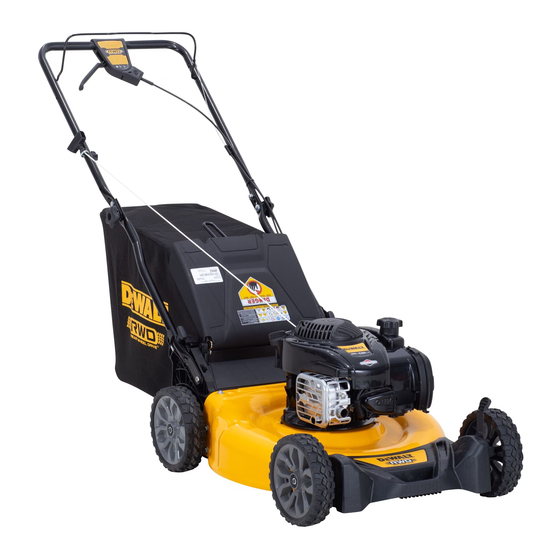
- Page 1 Instruction Manual DW12A-O1T9739 DW12AVP2R3739 Self-Propelled Mower If you have questions or comments, contact us. 1-855-971-1123 Form No. 769-26879 (November 21, 2023)
- Page 2 English (original instructions) Spanish (Español) © 2023 DEWALT. DEWALT® and GUARANTEED TOUGH® are registered trademarks of the DEWALT Industrial Tool Co., used under license. All rights reserved. The yellow and black color scheme is a trademark for DEWALT Power Tools and Accessories.
-
Page 3: Safe Operation Practices
SAFE OPERATION PRACTICES Definitions: Safety Alert Symbols and Words This instruction manual uses the following safety alert symbols and words to alert you to hazardous situations and your risk of personal injury or property damage. DANGER: Indicates an imminently hazardous situation which, if not avoided, will result in death or serious injury. -
Page 4: General Information
SAFE OPERATION PRACTICES WARNING: This symbol points out Preparation Before Operating important safety instructions which, if not 1. Thoroughly inspect the area where the mower is to followed, could endanger the personal safety be used. Remove all stones, sticks, wire, bones, toys, and/or property of yourself and others. - Page 5 SAFE OPERATION PRACTICES, cont'd c. Pull the mower back slowly, no more than half 14. A missing or damaged discharge door, chute or way toward you. mulch plug can cause blade contact or thrown object injuries. d. Repeat these steps as needed. 15.
- Page 6 SAFE OPERATION PRACTICES, cont'd Slope Operation for Walk-Behind 6. Never store the mower or fuel container inside where there is an open flame, spark or pilot light Mowers as on a water heater, space heater, furnace, clothes 1. Slopes are a major factor related to slip and fall dryer or other gas appliances.
-
Page 7: Spark Arrestor
SAFE OPERATION PRACTICES, cont'd 6. Regularly check the safety interlock system for When required, models are equipped with proper function, as described later in this manual. low permeation fuel lines and fuel tanks for If the safety interlock system does not function evaporative emission control. - Page 8 SAFE OPERATION PRACTICES, cont'd This page depicts and describes safety symbols that may appear on this mower. Read, understand, and follow all instructions on the mower before attempting to assemble and operate. Symbol Description WARNING — READ THE OPERATOR’S MANUAL(S) - Read, understand and follow all the safety rules and instructions in the manual(s) and on the mower before attempting to operate this mower.
-
Page 9: Mower Assembly
ASSEMBLY Handle Assembly IMPORTANT: This mower is shipped without gasoline or oil in the engine. Be certain to service engine with 1. Remove knobs or wing nuts (a) and carriage bolts gasoline and oil as instructed in the Operation section (b) from the handle (Figure 1). -
Page 10: Attaching The Grass Catcher
ASSEMBLY, cont'd 4. Reattach knobs or wing nuts (a) and carriage bolts 4. If necessary, tighten any loose cable ties (a)securing (b) removed in STEP 2 into the handle (Figure 3). cables to the handle (Figure 5). IMPORTANT: To reduce wear and allow for proper operation, make sure to leave some slack in the upper portion of the cables. -
Page 11: Cutting Height Adjustments
ASSEMBLY, cont'd Cutting Height Adjustments the handle brackets. Reinstall the rear mulch plug (if equipped). Release rear discharge door to allow it to This mower is equipped with one of three types of close rear opening of mower. cutting height adjustment. Refer to Single Lever, Dual Lever or Rear Wheel/Caster Wheels in this section. - Page 12 ASSEMBLY, cont'd Handle Pitch (If Equipped) Drive Control Adjustment For convenience of operation, you may adjust the pitch Single Lever and Dual Lever Drive of the handle. Perform one of the following. Controls (If Equipped) 1. Remove wing nuts and carriage bolts from handle If equipped, there is an adjustment wheel located in the (Figure 10).
-
Page 13: Controls And Operation
CONTROLS & OPERATION Figure 13 Features C. CUTTING HEIGHT ADJUSTMENT LEVER A. BLADE CONTROL The dual lever cutting height adjustment levers are The blade control is attached to the upper handle of located above the front and rear wheels. To adjust the the mower. -
Page 14: To Start Engine
CONTROLS & OPERATION, cont'd To Start Engine G. REAR MULCH PLUG (IF EQUIPPED) On select mowers, the mulch plug is a separate WARNING: Be sure no one other than the component. If equipped, this mulch plug must be operator is standing near the lawn mower installed into the rear bagging discharge area when while starting engine or operating mower. - Page 15 CONTROLS & OPERATION, cont'd Using Side Discharge Chute Single Lever Drive Control (If Equipped) (If Equipped) Once the engine is running, squeeze the single To use the mower without mulching or collecting grass, lever drive control against the upper handle to remove the grass catcher and ensure the rear mulch propel mower.
-
Page 16: Product Care
PRODUCT CARE General Recommendations Mower Maintenance • Always observe safety rules on the mower and in the Deck Cleaning manual(s) when performing any maintenance. At least once a season and before storage, clean the • The warranty on this mower does not cover underside of the mower deck to prevent build-up of items that have been subjected to operator grass clippings or other debris. - Page 17 PRODUCT CARE, cont'd 3. Turn mower on its side keeping the muffler side 8. Place blade bell support (b) on the blade (c). Align down and making sure that the air filter and the notches on the blade bell support with small holes carburetor are facing up.
-
Page 18: Customer Support
WALT ® -- LIMITED Customer Support WARRANTY For machines needing service or parts replacement please contact your local DEWALT® Service Center Three Year Limited Warranty or the Customer Support Department before For warranty terms, go attempting to return the machine. - Page 19 Inglés (traducido de las instrucciones originales) Español © 2023 DEWALT. DEWALT® and GUARANTEED TOUGH® are registered trademarks of the DEWALT Industrial Tool Co., used under license. All rights reserved. The yellow and black color scheme is a trademark for DEWALT Power Tools and Accessories.
- Page 20 Definiciones: Símbolos y Palabras de Alerta de Seguridad Este manual de instrucciones utiliza los siguientes símbolos y palabras de alerta de seguridad para alertarle de situaciones peligrosas y del riesgo de lesiones corporales o daños materiales. PELIGRO: Indica una situación de peligro inminente que, si no se evita, provocará la muerte o lesiones graves.
-
Page 21: Información General
PRÁCTICAS DE OPERACIÓN SEGURAS ADVERTENCIA : Este símbolo indica PREPARATIVOS ANTERIORES AL USO instrucciones de seguridad importantes que, 1. Revise minuciosamente el área donde se va a usar la cortadora de no seguirse, pueden poner en peligro su de césped. Saque todas las piedras, palos, cables, huesos, juguetes y otros objetos extraños con los que podría tropezar o seguridad personal y/o material y la de otras que podrían ser arrojados por la cuchilla. - Page 22 PRÁCTICAS DE OPERACIÓN SEGURAS (continuación) 4. No engrane el control de la transmisión (si se incluye) mientras 16. Detenga la cuchilla de la cortadora de césped cuando cruce enciende el motor. caminos o senderos de gravilla y cuando no esté cortando el césped.
-
Page 23: Servicio Y Mantenimiento
PRÁCTICAS DE OPERACIÓN SEGURAS (continuación) 2. Para su seguridad, antes de usar la cortadora de césped mida 8. Para reducir el riesgo de incendio mantenga la cortadora limpia cualquier pendiente que haya. Use un dispositivo de medición de pasto, hojas y de acumulación de otros escombros. Siga el de pendientes además del indicador de pendiente que se “Programa de Mantenimiento”... -
Page 24: Amortiguador De Chispas
PRÁCTICAS DE OPERACIÓN SEGURAS (continuación) AMORTIGUADOR DE CHISPAS 8. Controle el par de ajuste del perno de montaje del motor y cuchilla de la cortadora de césped de acuerdo con la sección ADVERTENCIA: Esta cortadora de césped está Servicio y Mantenimiento de este manual. Además, inspeccione equipada con un motor de combustión visualmente la cuchilla en busca de daños (por ejemplo, interna y no debe ser utilizada en o cerca de... - Page 25 PRÁCTICAS DE OPERACIÓN SEGURAS (continuación) En esta página, se presentan y describen los símbolos de seguridad que pueden aparecer en esta cortadora de césped. Lea, comprenda y siga todas las instrucciones que aparecen sobre la cortadora de césped antes de intentar armarla y hacerla funcionar. Símbolo Descripción ADVERTENCIA - LEA EL MANUAL DEL OPERADOR - Lea, entienda y cumpla todas...
-
Page 26: Montaje
MONTAJE Montaje de la Manija IMPORTANTE: Esta cortadora de césped se envía sin gasolina ni aceite en el motor. Antes de poner en Plegado de la manija marcha u operar su cortadora de césped, asegúrese de 1. Extraiga las perillas o las tuercas de mariposa (a) y los cargar el motor con gasolina y aceite como se indica en pernos de carro (b) de la manija (Figura 1). - Page 27 MONTAJE (continuación) 4. De ser necesario, ajuste cualquier brida de cable suelta (a) asegurándola a la manija(Figura 5). IMPORTANTE: Para reducir el desgaste y permitir la operación adecuada, asegúrese de dejar un poco de holgura en la porción superior de los cables. Figura 5 Acople del Colector de Césped (si se incluye)
-
Page 28: Ajustes De La Altura De Corte
MONTAJE (continuación) Colocación del Canal de Descarga 2. Para acoplar el colector de césped siga los pasos a continuación (Figura 7): Lateral (si se incluye) a. Eleve la puerta de descarga trasera (a). La cortadora de césped se envía como abonadora. Si b. - Page 29 MONTAJE (continuación) Ajuste del control de la transmisión 3. Libere la palanca hacia la plataforma. IMPORTANTE: Todas las ruedas deben ser colocadas en la Controles de la transmisión de misma posición. Cuando el terreno es agreste o irregular, palanca única y de palanca doble (si mueva cada palanca de ajuste de altura a una posición se incluyen) más alta.
- Page 30 FUNCIONAMIENTO Figura 13 Características 2. Controles de transmisión de doble palanca (si están equipados) - Los controles de transmisión A. CONTROL DE LA CUCHILLA de doble palanca se encuentran ubicados en El control de la cuchilla está unido a la manija superior la parte superior de la manija superior y se de la cortadora.
- Page 31 FUNCIONAMIENTO (continuación) Para Detener el Motor F. ADAPTADOR PARA ABONO (SI SE INCLUYE) El adaptador para abono está ubicado en el costado ADVERTENCIA: Asegúrese de que ninguna derecho de la cortadora y se usa para fines de abono persona aparte del operador permanezca (recirculando los recortes de regreso a la tierra).
- Page 32 FUNCIONAMIENTO (continuación) Controles de transmisión de doble Uso de la cortadora de césped como palanca (si se incluye) abonadora (si se incluye) 1. Una vez que el motor esté funcionando y mientras Para abonar el césped, quite el colector de césped o sigue oprimiendo el control de la cuchilla, apriete canal de descarga lateral de la máquina.
-
Page 33: Mantenimiento Del Motor
SERVICIO Y MANTENIMIENTO Recomendaciones Generales Limpie el motor • Antes de cada uso, limpie el césped, la grasa o los • Respete siempre las reglas de seguridad que figuran residuos acumulados del motor. Mantenga limpios el sobre la cortadora y en los manuales cuando realice varillaje, los resortes y los controles. - Page 34 SERVICIO Y MANTENIMIENTO (continuación) Cuidado de las Cuchillas 7. Lubrique el cigüeñal del motor y la superficie interna del adaptador de la cuchilla con aceite ligero. ADVERTENCIA:Espere a que la cuchilla se (recuadro de la (Figura 16 inset). haya detenido por completo antes de hacer a.
-
Page 35: Servicio De Atención Al Cliente
Para máquinas que requieran servicio o reemplazo LIMITADA de piezas, por favor contacte a su Centro de Servicio DEWALT® local o al Departamento de Garantía Limitada de Tres Años Atención al Cliente antes de intentar devolver la Para los términos de garantía, máquina. - Page 36 NOTES/NOTAS...
- Page 37 NOTES/NOTAS...
- Page 38 NOTES/NOTAS...
- Page 39 NOTES/NOTAS...
-
Page 40: Slope Gauge
SLOPE GAUGE...