
Related Manuals for ABB Smart


Summary of Contents for ABB Smart
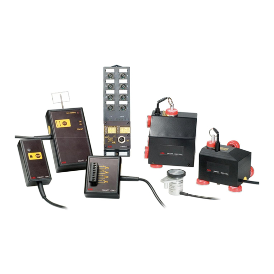
- Page 1 Original instructions Smart Safety and Motion Analyser Tool ABB AB / Jokab Safety Varlabergsvägen 11, SE-434 39, Sweden www.abb.com/lowvoltage...
- Page 2 DAMAGES, LOSS OF PROFITS OR COMMERCIAL LOSS IN ANY WAY CONNECTED WITH THE PRODUCTS, WHETHER SUCH CLAIM IS BASED ON CONTRACT, WARRANTY, NEGLIGENCE, OR STRICT LIABILITY. In no event shall responsibility of ABB/JOKAB SAFETY for any act exceed the individual price of the product on which liability asserted.
-
Page 3: Table Of Contents
SM11 – Flag unit ..........................15 Accessories ............................17 Smart Manager ..........................18 Installation ............................18 The first time you start Smart Manager ....................26 Quick guide to perform a measurement ....................26 Menu system ............................27 Settings ..............................28 Edit the analogue conversion ........................ -
Page 4: General
Different sensors and transducers can be connected to Smart to measure movement and forces, and different stop units can be connected to be able to send stop signals to the system. Smart can also communicate with the machine system using digital I/O’s. The program Smart Manager is used to control Smart. -
Page 5: Safety Instructions
3. The equipment should be sent for control to the manufacturer or a test laboratory once every year. 4. To guarantee the accuracy of the safety distance calculated using Smart Manager the user must use appropriate values in the formula for the calculation, and the user must also make sure that the formula is valid for the machine. -
Page 6: Hardware
For this reason the external units and I/O’s are powered using a 24 VDC power supply (SM6) and the CPU in Smart Logger is powered by the computer via the USB-cable. - Page 7 On the panel the pin assignment for the M12 connectors can be seen. The pin assignment is identical for all 8 connectors on Smart Logger. Please note that the connectors on the right side of the unit (connectors 2, 4, 6 and 8) are placed at a 90 degree angle.
- Page 8 To measure motion, speed and position a pulse sensor (SM5/SM7) is connected to Smart Logger. The pulse sensors have a resolution of 0.1 mm, i.e. they send 10 pulses/mm. Based on incoming pulses Smart Logger calculates at which position the sensors are and at what speed they move.
- Page 9 Response time The response time of Smart Logger is maximum 1 ms, i.e. from the moment a stop position is reached it can take at most 1 ms before a stop signal is given. Measuring accuracy The speed of the pulse sensor I8 is calculated based on a mean over 25 ms, which means that the stop time of a machine in most cases is correct, but in some special situations the actual stop time of the machine can be slightly less than the calculated stop time of the program.
-
Page 10: Sm2 - Pushbutton Unit
Black/Yellow Application The SM2 stop unit is used together with Smart Logger to give a stop signal without electrical connection to machines or control systems. SM2 is connected to any of the I/O connectors on Smart Logger. The pushbutton on the underside of SM2 initiates stop time or intermediate time measurement when it is pressed or released, depending on the settings of the New measurement form in Smart Manager. -
Page 11: Sm3 - Relay Unit
SM3 is connected to any of the I/O connectors on Smart Logger. Stop signal The SM3 gives stop signals to machines and starts the timing in Smart Logger when the output signal of SM3 is set as the stop signal in Smart Manager. -
Page 12: Sm5/1250 - Linear Transducer
Operation The transducer utilises a digital incremental pulse encoder with a resolution of 10 pulses/mm. Its two-channel pulse-train is evaluated by Smart Logger to determine the position, speed of movement, and direction of the moving machine part. 2TLC172188M0201, rev. H www.abb.com/lowvoltage... -
Page 13: Sm5/2500 - Linear Transducer
Operation The transducer utilises a digital incremental pulse encoder with a resolution of 10 pulses/mm. Its two-channel pulse-train is evaluated by Smart Logger to determine the position, speed of movement, and direction of the moving machine part. 2TLC172188M0201, rev. H www.abb.com/lowvoltage... -
Page 14: Sm7 - Rotating Transducer
The transducer utilises a digital incremental pulse encoder with a resolution of 10 pulses/mm. Its two-channel pulse-train is evaluated by Smart Logger to determine the position, speed of movement, and direction of the moving machine part. Note that all presented units are linear and can be transformed to rotational units using the circumference of the wheel (125 mm). -
Page 15: Sm11 - Flag Unit
Black Operation 1. Connect the plug on SM11 to any of the I/O connectors on Smart Logger. 2. If the transducers SM5, SM7 or other triggering equipment are to be used, these units must also be connected via appropriate connectors on Smart Logger. - Page 16 The SM11 stop flag unit is specifically designed to be used in conjunction with Smart Logger. Interfacing of this unit to other equipment may result in inaccurate timing and/or equipment malfunction.
-
Page 17: Accessories
24 VDC power supply for Smart Logger. 2TLA070300R0900 Carrying case for Smart. Battery pack for Smart Logger. Can be used instead of SM6 to make the system SM13 2TLA070300R2300 portable. Enough for 10 hours running time. SM13 is recharged using SM14. -
Page 18: Smart Manager
4 Smart Manager Installation In order to use Smart the following needs to be installed on the supervising computer: 1. .NET Framework Redistributable Package 2. Microsoft SQL Server 2000 Desktop Engine (MSDE) 3. Smart Manager 4. Drivers for communication with Smart Logger 1. - Page 19 Windows 2000 be found in the “Control Panel” – “System” under “Network Identification”. Select that the server should be auto-started on start up of the computer by checking the “Auto-start service when OS starts” checkbox. 2TLC172188M0201, rev. H www.abb.com/lowvoltage 2012-01-03...
- Page 20 3. Installation of Smart Manager Run the file SmartSetup.msi in the folder \Smart Manager on the installation CD and the installation program for Smart Manager will be started. Click Next. Read through the license agreement and click ”I agree” and Next if you agree to the terms of the license agreement.
- Page 21 Change the installation folder if you want a different folder than the default. Select if you want Smart Manager to be available for all users on the computer or only your own user. Click next. Click next to start the installation.
- Page 22 4. Installation of drivers for communication with Smart Logger When Smart Logger is connected to the USB port Windows will launch the Found New Hardware Wizard and ask for USB serial converter (Virtual COM port) drivers for Smart Logger. The following series of pictures describes the installation procedure on Windows XP. Please note that the messages displayed on Windows 2000 or any other operating system will be slightly different.
- Page 23 When the drivers for Smart Logger have been installed the Found New Hardware Wizard will continue to install the USB serial port (COM port emulation) driver. Select not to connect to Windows Update, and click Next. 2TLC172188M0201, rev. H www.abb.com/lowvoltage...
- Page 24 FTDIPORT.INF in the folder \Drivers on the installation CD.) When the installation is finished you can find which COM port number Smart Logger has been assigned by opening the Device Manager (located in “Control Panel” – “System” then select the “Hardware” tab and click “Device 2TLC172188M0201, rev.
- Page 25 Manager”). Smart Logger appears as an additional COM port with the label “USB Serial Port” and the port number in parenthesis under the Ports node. 2TLC172188M0201, rev. H www.abb.com/lowvoltage 2012-01-03...
-
Page 26: The First Time You Start Smart Manager
The first time you start Smart Manager License If it’s the first time Smart Manager is started or if you haven’t supplied any license key for Smart, you will be prompted for a license key on start up of Smart Manager. -
Page 27: Menu System
From the new measurement form a measurement is performed. Information about the New measurement current status of Smart Logger is shown and the setup of a measurement can be chosen. On the graph form a graph of the measurement is shown and from here you can get Graph details of the measurement and compare it to other measurements. -
Page 28: Settings
Logger is displayed under Ports as ’USB Serial Port’. The button ”Calibrate analogue input” displays a form where the analogue input for Smart can be calibrated. The button “Edit analogue conversion” shows a form where the analogue input can be converted to show any units and values when displayed in the graph. -
Page 29: Calibrating The Analogue Input
2. Connect the larger of the two currents to I9. 3. Enter the known larger current in the top left textbox in the top frame. 4. Read Smart’s value of the current in the bottom left frame and enter it in the upper right textbox in the top frame. -
Page 30: Performing A Measurement
Current data The top left frame (Current data) shows the current inputs and outputs of Smart. ”Position, I8” shows the current position for the transducer on I8 in mm. - Page 31 The top right frame (Measurement) is activated when a measurement has started. With the button “Manual signal” a signal is given to Smart which tells it to consider the conditions of the current measurement phase as fulfilled and move on to the next phase, regardless of whether the conditions have been met or not.
- Page 32 This sets the system in a state where the conditions in phase 1 are monitored. It’s not until any of these conditions are met that any data is recorded. The button “Cancel” closes the form. 2TLC172188M0201, rev. H www.abb.com/lowvoltage 2012-01-03...
-
Page 33: Displaying Measurements
X- and Y-axes Time is shown along the x-axis. If Smart has received a positive signal from the selected stop signal, that signal marks the time zero (0). The time before that signal is regarded as negative time. If no stop signal has been received the time zero is the start of the measurement. - Page 34 In the two bottom textboxes (Marker difference) the difference between the markers are shown both in time and y- values. By clicking “+” and “-“ the markers are moved one step (one ms) forwards or backwards in the measurement. 2TLC172188M0201, rev. H www.abb.com/lowvoltage 2012-01-03...
- Page 35 ”Stop time and safety distance” shows a form where the stop time can be calculated based on multiple measurements and the minimum allowed safety distance for the machine can be calculated. Under ”Help” information about the program version can be found. 2TLC172188M0201, rev. H www.abb.com/lowvoltage 2012-01-03...
-
Page 36: Calculating Stop Time And Safety Distance
The button “Save” saves the selected stop times and safety distance calculations to the measurement in the database. The button “Close” closes the form. 2TLC172188M0201, rev. H www.abb.com/lowvoltage 2012-01-03... -
Page 37: Compare Measurements
“Exit” closes the form. When a new layer is added to the list on top of another layer, the zoom is automatically adjusted after the existing layer so that the measurements can be compared. 2TLC172188M0201, rev. H www.abb.com/lowvoltage 2012-01-03... - Page 38 A small form is then shown where the zoom can be specified. If a layer has been saved before, the same zoom can be set by clicking the button “Last configuration” and then “Apply”. 2TLC172188M0201, rev. H www.abb.com/lowvoltage 2012-01-03...
-
Page 39: Save Measurements
In the textbox ”Measurement performed by” the person/company who performed the measurement is entered. The textbox ”Date” displays the date and time of the measurement. ”Smart hardware ID” shows the ID number of the Smart that the measurement was performed with. “Safety distance” shows the calculated safety distance for the measurement if it exists. -
Page 40: Load Measurements
“Machine LIKE press OR Date < 2005-01-01” displays all measurements where the machine name contains the word “press”. But it also displays all measurements (independent of machine names) that were made prior to the year 2005. 2TLC172188M0201, rev. H www.abb.com/lowvoltage 2012-01-03... -
Page 41: Importing And Exporting Measurements
The three CSV files (Measurements.csv, Values.csv and Conditions.csv) can now be copied or moved to another computer and placed in the folder where Smart Manager was installed. Please note that you need all three files for the import/export to work properly. When you open the import/export function in Smart manager the measurements should be visible in the external database. -
Page 42: Printing Measurements
In the top left corner of the print and the saved picture, there is a field intended for company logotypes. As a default Jokab Safety’s logotype is displayed. The picture that is shown is in Smart Managers installation folder and is called company_logo.bmp. - Page 43 2TLC172188M0201, rev. H www.abb.com/lowvoltage 2012-01-03...
- Page 44 2TLC172188M0201, rev. H www.abb.com/lowvoltage 2012-01-03...