
Related Manuals for ABB TRIO-WIRL ST4000


Summary of Contents for ABB TRIO-WIRL ST4000
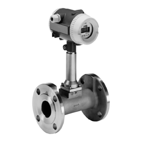
- Page 1 INSTRUCTION MANUAL TRIO-WIRL Flowmeter Swirl ST4000/SR4000 Vortex VT4000/VR4000 PN25080...
- Page 2 This document contains proprietary information of ABB Inc., and is issued in strict confidence. Its use, or repro- duction for use, for the reverse engineering, development or manufacture of hardware or software described herein is prohibited.
-
Page 3: Table Of Contents
TRIO-WIRL INSTRUCTION MANUAL Table of Contents Page Read First ..........I CHAPTER 1 Introduction . - Page 4 TRIO-WIRL INSTRUCTION MANUAL Table of Contents (cont.) Page 3.4.2.3 Wafer-Style Installation......... . 3-6 3.4.2.4 Flanged-Style Installation .
- Page 5 TRIO-WIRL INSTRUCTION MANUAL Table of Contents (cont.) Page 5.3 Converter Configuration........... . . 5-5 5.3.1 Data-Entry Check .
- Page 6 TRIO-WIRL INSTRUCTION MANUAL List of Figures Page FIGURE 2-1 MEASUREMENT PRINCIPLE, TRIO-WIRL S ....... . 2-1 FIGURE 2-2 OPERATING PRINCIPLE, TRIO-WIRL S .
- Page 7 TRIO-WIRL INSTRUCTION MANUAL List of Figures (cont.) Page FIGURE 5-7 TRANSMITTER POWER SUPPLY......... 5-3 FIGURE 5-8 LOAD DIAGRAM .
-
Page 8: Read First
RETURN OF EQUIPMENT All equipment being returned to ABB Inc. for repair must be free of any hazardous materials (acids, alkalis, solvents, etc.). A Material Safety Data Sheet (MSDS) for all process liquids must accompany returned equipment. - Page 9 Incidental scratches and other finish damage must be repaired and promptly re-painted with approved touch-up paint. Provide the model number and size of your product to the nearest ABB Automation representative to obtain the correct touch-up paint. PN25080...
-
Page 10: Chapter 1 Introduction
TRIO-WIRL INSTRUCTION MANUAL CHAPTER 1 Introduction 1.1 Description The ABB Inc. TRIO-WIRL family of flowmeters consists two line, 16 character LCD display permits continuous of the TRIO-WIRL V vortex flowmeter and the monitoring of the flow rate or other flow parameters. -
Page 11: Features
TRIO-WIRL INSTRUCTION MANUAL Remote Mounted Design: The converter remotely mounted up to 10m from the flowmeter primary.. Vortex Flowmeter Vortex Flowmeter Swirl Flowmeter TRIO-WIRL VR TRIO-WIRL VR TRIO-WIRL SR Wafer Design Flanged Design Flanged Design 1.2 Features 1.3 Organization The remainder of this instruction manual is organized into four main sections: No Moving Parts Swirlmeter (TRIO-WIRL S) Primaries... -
Page 12: Chapter 2 Swirlmeter (Trio-Wirl S)
TRIO-WIRL INSTRUCTION MANUAL CHAPTER 2 Swirlmeter (TRIO-WIRL S) 2.1 General Outlet Guide Piezo Body Sensor The volumetric flowrate of steam, gases and liquids can be measured over wide flow ranges independent Inlet Guide of the fluid properties with this newest member to the Body Swirlmeter line. -
Page 13: Swirlmeter Model Number Breakdown
TRIO-WIRL INSTRUCTION MANUAL 2.3 Swirlmeter Model Number Breakdown Refer to the ABB Inc. data sheet or the data tag on the nished. The details of a specific number are shown on equipment for the model number of the equipment fur- the following pages. - Page 14 TRIO-WIRL INSTRUCTION MANUAL Swirlmeter Model Number Breakdown (Cont.) TRIO-WIRL S Pressure Rating ANSI CL 150 ANSI CL 300 ANSI CL 600 Other Sensor Design Standard, single sensor Standard, single sensor with integr. temperature sensor Temperature Range Fluid/Gaskets Kalrez O-Ring 32 °F to 536 °F (0 °C to 280 °C) Viton O-Ring -67 °F to 446 °F (-55 °C to 230 °C) (not for steam) PTFE O-Ring...
-
Page 15: Installation
However, it is good practice to minimize mechanical vibrations using may result, contact ABB Inc. before installation. Always supports if required. When installing in long pipe- reference the complete instrument serial number and... -
Page 16: Control Valve Installation
TRIO-WIRL INSTRUCTION MANUAL FIGURE 2-4 RECOMMENDED FLANGE BOLT TIGHTENING SEQUENCE When this is not possible, the control valve should be located > 3D upstream of the flowmeter. FIGURE 2-3 METER PIPING REQUIREMENTS Mounting bolts and nuts are supplied by the user. During installation, make certain that the flow direction arrow on the meter body is oriented in accordance with the process flow. -
Page 17: Figure 2-6 Insulating The Pipeline
TRIO-WIRL INSTRUCTION MANUAL WARNING WHEN THE METER IS USED IN A VERY HIGH OR LOW TEMPERATURE PROCESS, THE TEMPER- ATURE OF THE METER BODY MAY BE EXTREMELY HOT OR COLD. IF IT IS NECES- SARY TO TOUCH THE SENSOR HOUSING OR METER BODY, INSULATED GLOVES MUST BE WORN TO PREVENT SERIOUS INJURY. -
Page 18: Temperature/Pressure Monitoring
TRIO-WIRL INSTRUCTION MANUAL 2.4.3 Temperature/Pressure Monitoring Provisions for temperature and/or pressure monitoring are the responsibility of the user. The temperature sen- sor should be located a minimum of three pipe diame- ters downstream of the flowmeter. Measurement is from the downstream face of the meter. An option is available for the Swirlmeter for direct Pt100 temperature measurements. -
Page 19: Example For Gases
TRIO-WIRL INSTRUCTION MANUAL ρ = Density at operating conditions [lb/ft TABLE 2-2. STANDARD DENSITIES FOR ρ = Density at standard conditions [lb/ft SELECTED GASES = Pressure at operating conditions [psig] Standard Density [lb/ft = Temperature at operating conditions [°F] Acetylene 0.0732 = Actual volume flowrate [acfh] 0.0749... -
Page 20: Figure 2-10 Pressure Drop, Air
TRIO-WIRL INSTRUCTION MANUAL [ ft /h ] F, 14.7 PSI, Ρ=0.075 LB/FT FIGURE 2-10 PRESSURE DROP, AIR ( @70 PN25080 Swirlmeter (TRIO-WIRL S) 2 - 9... -
Page 21: Liquid
TRIO-WIRL INSTRUCTION MANUAL 2.5.2 Liquid 2. Pressure Drop [psi] See Figure 2-11 for water (ρ= 8.34 lb/gal) The maximum required flowrate should not be less than 0.5 x Qvmax if possible, but can be set as low as For other fluid densities the pressure drop can be cal- 0.15 Qvmax if required. -
Page 22: Saturated Steam
TRIO-WIRL INSTRUCTION MANUAL FIGURE 2-11 PRESSURE DROP, WATER ( @ Ρ = 8.34 LB/GAL ) 2.5.3 Saturated Steam [lb/h] 2.5.3.1 Example for Saturated Steam: Find the flow range for a 2” /DN50 meter size at 60 psig. 1. Table shows the range for a 2” / DN50 meter is 110 - 2120 lb/h (always use the next highest pressure rating). -
Page 23: Table 2-4. Swirl Flow Ranges, Saturated Steam
TRIO-WIRL INSTRUCTION MANUAL TABLE 2-4. SWIRL FLOW RANGES, SATURATED STEAM Meter Size [psig] Inch 1015 1205 1-1/4 1175 1425 1675 2160 2640 3125 1-1/2 1215 1805 2190 2575 3315 4060 4800 1310 2130 3155 3830 4505 5805 7100 8400 1220 1440 2160 3185... -
Page 24: Specifications
TRIO-WIRL INSTRUCTION MANUAL 2.6 Specifications 2.6.1 Model Overview ST4000 SR4000 MODEL ≤ ± 0.5 % of rate Liquids Accuracy ≤ ± 0.5 % of rate Gases and Steam ≤ ± 0.2 % of rate Reproducibility to 2”/DN50 ≤ 10 cps Allowable viscosity for liquids ≥... -
Page 25: Detailed Specifications
TRIO-WIRL INSTRUCTION MANUAL 2.6.2 Detailed Specifications FLUID TEMPERATURE: - 67 F to 536 F (-55 C to +280 C) (Standard) ACCURACY & REPRODUCIBILITY OF FLOW MEASUREMENT Allowable temperature range for the gasket material must be Accuracy (incl. converter): < ± 0.5% of rate considered. -
Page 26: Figure 2-12 Ambient / Fluid Temperature Relationship
TRIO-WIRL INSTRUCTION MANUAL Cables for the supply power, termi- nals 31 & 32, and the contact output, Allowable terminals 41 & 42, which are suitable Temperature Range for temperatures to 230 F (110 can be used without any temperature reductions. Side View of Pipeline Cables which are only suitable for tem- peratures to 176... - Page 27 REF. OD-10-2829_r0...
-
Page 28: Chapter 3 Vortex Meter (Trio-Wirl V)
TRIO-WIRL INSTRUCTION MANUAL CHAPTER 3 Vortex Meter (TRIO-WIRL V) 3.1 General The frequency f of the vortex shedding is proportional to the flow velocity v and inversely proportional to the width of the shedder body d: The volumetric flowrate of steam, gases and liquids can be measured over wide flow ranges independent -- - ×... - Page 29 TRIO-WIRL INSTRUCTION MANUAL PIEZO-SENSOR SHEDDER (Option: with PT100) FIGURE 3-3 OPERATING PRINCIPLE, TRIO-WIRL V Vortex Meter (TRIO-WIRL V) 3 - 2 PN25080...
-
Page 30: Vortex Model Number Breakdown
TRIO-WIRL INSTRUCTION MANUAL 3.3 Vortex Model Number Breakdown Refer to the ABB Inc. data sheet or the data tag on the nished. The details of a specific number are shown on equipment for the model number of the equipment fur- the following pages. - Page 31 TRIO-WIRL INSTRUCTION MANUAL Vortex Model Number Breakdown (Cont.) TRIO-WIRL V Pressure Rating ANSI CL 150 ANSI CL 300 ANSI CL 600 Other Sensor Design Standard sensor Standard sensor with integral temperature sensor High Temperature [<750 F (400 C)] sensor Temperature Range Fluid/Gaskets Graphite -67 °F to 536 °F (-55 °C to 280 °C) Graphite Special...
-
Page 32: Installation
Assuming a properly supported pipeline and the converter’s DSP signal processing technology, may result, contact ABB Inc. before installation. Always vibration problems should not be encountered in reference the complete instrument serial number and normal industrial applications. -
Page 33: Wafer-Style Installation
TRIO-WIRL INSTRUCTION MANUAL 3.4.2.3 Wafer-Style Installation centering devices The wafer type meter body mounts inside the pipe flange bolt circle and ranges in size from 1/2 to 8 inches. To assure optimum meter performance, the meter should be installed in accordance with the upstream and downstream straight run piping require- ments given in Figure 3-4. -
Page 34: Figure 3-5 Wafer Process Connections, Sizes 1/2 Through 2 Inches
TRIO-WIRL INSTRUCTION MANUAL Install the remaining mounting studs, as required. diagonally opposite pattern, as shown in Figure 3-8, to Studs and nuts should be lubricated with a graphite equalize pressure on the meter face. Nut torque should based lubricant. Assemble a nut on each end of the be limited to that which will provide a leakproof seal. -
Page 35: Flanged-Style Installation
TRIO-WIRL INSTRUCTION MANUAL FIGURE 3-6 WAFER PROCESS CONNECTIONS, SIZES 3 THROUGH 8 INCHES When properly installed, the installation should look like 3.4.2.4 Flanged-Style Installation that shown in Figure below. Place the two supplied flange gaskets against the upstream and downstream flange faces (Refer to Table for replacement flange gaskets). -
Page 36: Control Valve Installation
TRIO-WIRL INSTRUCTION MANUAL 3.4.2.5 Control Valve Installation Control valves should be installed downstream from the flow- meter as shown in Figure 3-10. When this is not possible, the control valve should be located > 50D upstream from the flow- meter. Refer to Figure FIGURE 3-10 CONTROL VALVE INSTALLATION 3.4.2.6 Extreme Temperature Applications... -
Page 37: Temperature/Pressure Monitoring
TRIO-WIRL INSTRUCTION MANUAL Allowable Temperature Range HT-Design for Std. Design ≤ 400°C Side View, Pipeline (≤ 280°C) Installation for Fluid Temperatures > 150°C Fluid Temperature [°C] FIGURE 3-13 AMBIENT/FLUID TEMPERATURE RELATIONSHIP FIGURE 3-11 INSULATING THE PIPELINE 1) Cables suitable 230 F (110°C) can be used for the power supply terminals 31, 32 and the contact output terminals 41, 42 without any reduction in the temperature range specifications. -
Page 38: Vortex Meter Size Selection
TRIO-WIRL INSTRUCTION MANUAL 3.5 Vortex Meter Size Selection Where: ρ = Density at operating conditions (lb/ft The maximum required actual volume flowrate Q ρ = Density at standard conditions (lb/ft operating conditions is the basis for the flowmeter size = Pressure at operating conditions (psig) selections. -
Page 39: Example For Gases
TRIO-WIRL INSTRUCTION MANUAL TABLE 3-3. MINIMUM & MAXIMUM FLOWRATES VS. DENSITY, GASES & STEAM [ACFH] vmin Density <0.08 0.09 >2.0 Qvmax Freq. [Hz] [ACFH] at Qvmax Meter Size Inch 1840 2900 1825 1-1/2 12000 2000 1500 1500 1500 15900 1250 2750 2600 2400... -
Page 40: Figure 3-14 Pressure Drop, Air
TRIO-WIRL INSTRUCTION MANUAL FIGURE 3-14 PRESSURE DROP, AIR @70 F & 14.7 psia TABLE 3-4. VORTEX FLOW RANGES, SATURATED STEAM [LB/H] Meter Size [psig] Inch 1055 1360 1665 1970 1-1/2 1275 2065 3060 3720 4370 5630 6890 8150 1020 1145 1685 2735 4055... -
Page 41: Liquid
TRIO-WIRL INSTRUCTION MANUAL 3.5.2 Liquid. 3.5.2.2 Pressure Drop, Liquids See Figure below for water (70ºF, 14.67 psia, ρ - 8.34 TABLE 3-5. VORTEX FLOW RANGES, WATER lb/gal). For other fluid densities (ρ) the pressure drop can be calculated using the following equation: Flow Range Frequency Meter Size... -
Page 42: Figure 3-15 Pressure Drop, Water
TRIO-WIRL INSTRUCTION MANUAL FIGURE 3-15 PRESSURE DROP, WATER (70 F, 14.67 psia, ρ=8.34 lb/gal) PN25080 Vortex Meter (TRIO-WIRL V) 3 - 15... -
Page 43: Specifications
TRIO-WIRL INSTRUCTION MANUAL 3.6 Specifications 3.6.1 Model Overview VT4000 VR4000 MODEL Liquids ≤ ± 0.75 % of rate Accuracy ≤ ± 1 % of rate Gases and Steam ≤ ± 0.2 % of rate Reproducibility Allowable viscosity for liquids ≤ 7.5 cps Typical flow range 1:20 Typical up-/downstream straight lengths... -
Page 44: Detailed Specifications
TRIO-WIRL INSTRUCTION MANUAL 3.6.2 Detailed Specifications WEIGHTS: Refer to the dimensional outline drawing (Figure 3-18) ACCURACY AND REPRODUCIBILITY OF FLOW MEASUREMENT FLUID TEMPERATURE Accuracy (incl. converter), linear flow range (Re > 20,000 for 6”/DIN 150 > 40,000): - 67 F to 536 F (-55 C to +280 C) (Standard) -
Page 45: Figure 3-16 Ambient / Fluid Temperature Relationship
TRIO-WIRL INSTRUCTION MANUAL Cables for the supply power, terminals 31 & 32, and the contact output, terminals 41 & 42, which are suitable for temperatures to Allowable T= 230 F (110°C), can be used Temperature Range HT-Design without any temperature reduc- for Std. - Page 46 REF. OD-10-2828_r0...
-
Page 47: Chapter 4 Converter
TRIO-WIRL INSTRUCTION MANUAL CHAPTER 4 Converter 4.1 General The TRIO-WIRL flow metering system is designed as a wall-mounted or pipe-mounted (pipe-mounting hard- 2-wire instrument, i.e. the supply power and the current ware is shown in Figure 4-3).The remote design also output signal (4-20 mA) both use the same pair of con- offers advantages when the ambient conditions at the nection leads. -
Page 48: Converter Positioning
TRIO-WIRL INSTRUCTION MANUAL After the installation has been completed, the cable must be made with care and the leads positioned in the can be cut to the length required to reach he flowmeter connection box so that they are not affected by vibra- primary. -
Page 49: Enter Function For Magnetic Stick Operation
TRIO-WIRL INSTRUCTION MANUAL STEP C/CE DATA Buttons for C/CE The C/CE-key is used to toggle back and Direct Entry forth between the operating mode and the menu display. It is also used for the "exit" Magnetic function to exit from the menus. Sensors STEP ↑... -
Page 50: Data Entry Overview
TRIO-WIRL INSTRUCTION MANUAL 4.3.2 Data Entry Overview Action Use Keys= Display Information Qv % Standard-Display Turn off Locked mode 10.5 ↓ ↓ ↓ Progr. 1) Advance to Progr. Level STEP or DATA Level ↓ ↓ ↓ Locked Note: 2) Enter Menu ENTER The program protection ↓... -
Page 51: Operation And Configuration
The HART-Protocol provides for digital communication between a process control system/PC, handheld termi- 2. Over ABB Automation Products HART-Multiplexer. nal and the TRIO-WIRL. All parameters, such as meter SMART VISION is compatible with standard modern location specific data, can be transmitted from the con- PC’s or notebook computers running MS Windows Ver-... -
Page 52: Baudrate
TRIO-WIRL INSTRUCTION MANUAL 4.5.1.3 Baudrate 1200 Baud Logic 1: 1200 Hz Logic 0: 2200 Hz Current Output During an Alarm Condition = 22.4 mA (Available Soon) (Available Soon) FIGURE 4-6 HART-Communication Converter 4 - 6 PN25080... -
Page 53: Specifications
TRIO-WIRL INSTRUCTION MANUAL 4.6 Specifications 4.6.1 Overview TRIO-WIRL ST TRIO-WIRL SR TRIO-WIRL VT TRIO-WIRL VR CONVERTER For analog output 4-20 mA 14-46 V (EEx < 28 V) Supply Power For Profibus PA (in prep.) < 10 mA Self Monitor Display 2 x 8 character Local display/totalization and Magnet Stick operation (Optocoupler for standard... -
Page 54: Detailed Specifications
TRIO-WIRL INSTRUCTION MANUAL 4.6.2 Detailed Specifications (LOW FLOW CUTOFF): VMIN Can be set between 0 and 10% of Q (maximum actual vol- KEYPAD & DISPLAY vmax ume flowrate for the flowmeter size). SUPPLY POWER: Standard: 14 to 46 V DC Ex-Design: 14 to 28 V DC 3 Buttons for... -
Page 55: Figure 4-8 Outline Dimensions, Vr/Sr In Wall-Mount Housing
TRIO-WIRL INSTRUCTION MANUAL 1.22 4.92 2.13 (1.46)* 2.24 0.85 ( )* = w/o Display 3.94 All Dimensions Shown in Inches FIGURE 4-8 OUTLINE DIMENSIONS, VR/SR IN WALL-MOUNT HOUSING PN25080 Converter 4 - 9... -
Page 56: Chapter 5 Start-Up & Operation
EPROM. When communicating with ABB Inc., please reference the firmware version of the instrument. If everything is properly installed and connected, turn on the power to the meter. -
Page 57: Trio-Wirl Vr/Sr4000 Remote
TRIO-WIRL INSTRUCTION MANUAL After the installation has been completed, the cable may be cut to the length required to reach the flowme- ter primary. Because the signals between the flowme- ter primary and converter are not amplified, all connections must be made with care and the leads positioned in the connection box so that they are not Power Supply/ affected by vibrations. -
Page 58: Power Supply Interconnections
TRIO-WIRL INSTRUCTION MANUAL Converter TRIO-WIRL VR/SR Supply Power Flowmeter Primary Ground TRIO-WIRL VR/SR FIGURE 5-5 INTERCONNECTIONS BETWEEN CONVERTER AND FLOWMETER PRIMARY 5.2.3 Power Supply Interconnections 5.2.3.1 Power Supplied from a Central Power =Supply voltage TRIO-WIRL = min. 14 V DC Supply =Supply voltage, 14 - 46 V DC =Max. -
Page 59: Figure 5-9 Power Supply Interconnection Diagram, Hazardous Locations
TRIO-WIRL INSTRUCTION MANUAL Ref. FIGURE 5-9 POWER SUPPLY INTERCONNECTION DIAGRAM, HAZARDOUS LOCATIONS Ref. - r - r FIGURE 5-10 FM / CSA LABEL Start-Up & Operation 5 - 4 PN25080... -
Page 60: Contact Output Connections
TRIO-WIRL INSTRUCTION MANUAL 5.2.4 Contact Output Connections 4.Which flowrate units are to be used for the display indications and for the totalizer values? Mass Units Volume Units Parameter Action Parameter Action Operating select Operating mode select from Con- mode Volume, Normal table tact Input, SPC etc. -
Page 61: Calibration K-Factor
TRIO-WIRL INSTRUCTION MANUAL 5.3.2.2 Calibration K-Factor The converter calculates the actual flowrate using the follow- ing equations: Median -- - k-Factor Where: Q= Actual flowrate at operating conditions [m The median (average) k-Factor value is displayed by f = Frequency [1/s] navigating to the above menu item and pressing Enter. -
Page 62: Submenu Pulse Output
TRIO-WIRL INSTRUCTION MANUAL 5.3.2.5 Submenu Pulse Output All errors detected are permanently stored in the error register, whether they occurred momentarily or for a PULSE FACTOR long time period. This menu is used to configure the scaled pulse output to the Every number in the error register display represents a user requirements. -
Page 63: Configuring The Contact Output
TRIO-WIRL INSTRUCTION MANUAL Where: = Normal flowrate at normal conditions = Actual flowrate at operating conditions = Pressure at operating conditions = Temperature at operating conditions [°C] ρV = Density at operating conditions ρN = Density at normal conditions 5.3.3 Configuring the Contact Output The contact output of the converter is configured at the factory based on the specified Model Number. -
Page 64: Trio-Wirl Menu Structure
1ST LEVEL: STANDARD 3RD LEVEL: SERVICE The standard menu provides a quick means for config- The Service-Menu is only accessible to ABB Inc. Cus- uring the instrument. All user specific menu entries tomer Service personnel. required for operating the instrument can be set in this 4TH LEVEL: LOCKED menu. -
Page 65: Trio-Wirl Menu Display And Selections
TRIO-WIRL INSTRUCTION MANUAL ρ = Standard flowrate [scfh] = Operating density (lbs/ft oper = Mass flowrate [lb/h] To = Reference temp., oC = Actual volume flowrate [acfhh Toper = Operating temp., oC = Normal flowrate [ncfh] = Standard temp. (60 or 70 = Operating pressure (psia) = Normal temp. -
Page 66: Turning Locked Mode On/ Off
TRIO-WIRL INSTRUCTION MANUAL 5.5.2 Turning Locked Mode On/ Off After power-up, the converter operates in the Locked mode and data may not be entered. In order to enter or change data, the mode must be changed to either the Standard, Specialist or Service mode. The mode-change is made in the Program Level menu. - Page 67 TRIO-WIRL INSTRUCTION MANUAL After completing the programming/configuration of the converter, the Program Protection should be turned on again ⇒ Action = Display Information Qv % Turn Locked mode ON Standard Display 10.5 ↓ ↓ ↓ Progr. Advance to Progr. Level STEP or DATA Level ↓...
-
Page 68: Top-Level Menu Structure
TRIO-WIRL INSTRUCTION MANUAL 5.5.3 Top-Level Menu Structure The table to the right lists all of the top-level menus contained in the TRIO-WIRL firmware vs. the four menu pro- gramming modes: TABLE 5-1. TOP-LEVEL MENU STRUCTURE Menu Programming Levels/Modes Menu Item Locked Standard Specialist... -
Page 69: Complete Menu Structure Overview And Data Entry
SRV-Code_ Service: This menu includes additional parameters which ENTER can be accessed after enter- ing the correct Service Code No. (only for ABB Service) Pg.Prot Code Code ENTER If a number differing from "0“ 9999 (Factory setting) has been... - Page 70 TRIO-WIRL INSTRUCTION MANUAL Submenu/ Submenu/ Entry Submenu/Parameter Parameter Select Selections Comments Type Setting Parameter Flow Mode: Fluid = Liquid Liquid Liquid from table Flow Enter (Refer to Section 5.4.1) mode ENTER Fluid = Liquid Liquid Flow Mode: Mass Qm(D) (Refer to Section 5.4.1) Notes: Fluid = Liquid Liquid...
- Page 71 TRIO-WIRL INSTRUCTION MANUAL Submenu/ Submenu/ Entry Submenu/Parameter Parameter Select Selections Comments Type Setting Parameter Menu displayed for selection: 14,7 psi 1.0133 bara standard Enter Gas Mass Qm(pT) abs 70F 20 °C Conditions ENTER Gas Norm Qn (pT) 1.0133 bara 0 °C 14,7 psi abs 70F 14,7 psi...
- Page 72 TRIO-WIRL INSTRUCTION MANUAL Submenu/ Submenu/ Entry Submenu/Parameter Parameter Select Selections Type Setting Parameter Set the totalizer to a pre- Totaliz Totaliz 0.0000 numeric defined value er Value ft3_ ENTER ENTER Display of the totalizer over- Overflow Enter flows; max. 65,535 1 overflow = 10,000,000 m3, ft3, usgal, igal, igl, from table Selection of the units for the...
- Page 73 TRIO-WIRL INSTRUCTION MANUAL Submenu/ Submenu/ Entry Submenu/Parameter Parameter Select Selections Comments Type Setting Parameter For internal and external flow 0.001 - 1000 Pulse Enter numeric totalizers pulses/unit 100.000 1/ft3_ Factor ENTER Note: The Pulse Width menu is only displayed for the Selected units for output I/HART/Pulse_Bin selection.
- Page 74 TRIO-WIRL INSTRUCTION MANUAL Submenu/ Submenu/ Entry Submenu/Parameter Parameter Select Selections Comments Type Setting Parameter Test current output manual Iout Self Enter 0 to 115 % numeric control (100 % = 20 mA) check ENTER ENTER Simulation (current and pulse outputs). Initiate by entering a start value in “Hz“.
-
Page 75: Submenu Error Register
TRIO-WIRL INSTRUCTION MANUAL 5.5.5 Submenu Error Register This menu contains the error register and the power 5.5.5.1 Error Display supply interruption counter. Error Error ...3.56.. Register All errors detected are permanently stored in the error register, whether they occurred momentarily or for a longer time period. Every character in the error register display represents a specific error: Error..3.56.. -
Page 76: Chapter 6 Troubleshooting
22.4 mA during an error condition as shown below: WARNING ALL FLOWMETERS AND/OR SIGNAL CONVERT- Flowrate ERS BEING RETURNED TO ABB INC. FOR REPAIR MUST BE FREE OF ANY HAZARDOUS > 1 1 5 % MATERIALS (ACIDS, ALKALIS, SOLVENTS, ETC.). -
Page 77: Chapter 7 Parts List
CHAPTER 7 Parts List 7.1 Replacement Parts The following pages show a cutaway view of the flowmeters and indicate replacement parts that are available for the meters along with their ABB Inc. ordering numbers. PN25080 Parts List 7 - 1... - Page 78 REF.
-
Page 79: Flowmeter/Signal Converter Parts
TRIO-WIRL INSTRUCTION MANUAL 7.1.1 Flowmeter/Signal Converter Parts Refer to Figure for location of item numbers. TABLE 7-1. FLOWMETER/SIGNAL CONVERTER PARTS LIST ITEM QTY. DESCRIPTION PART NUMBER SENSOR Stainless Steel: Sensor w/Remote Electronics D693B042U06 Sensor w/PT100 w/Remote Electronics D693B043U06 Sensor w/Integral Electronics D693B042U14 Sensor w/PT100 w/Integral Electronics D693B043U14... -
Page 80: Kits / Accessories
TRIO-WIRL INSTRUCTION MANUAL TABLE 7-1. FLOWMETER/SIGNAL CONVERTER PARTS LIST (cont.) ITEM QTY. DESCRIPTION PART NUMBER REAR COVER Cover D612A167U02 338C686U01 O-Ring 1951779A042 D674A659U01 ELECTRONICS MODULE (Design Level A)) Electronics 4-PCB Assembly With Display D674A629U07 (Design Level B) SCREWS & LOCKWASHER, SENSOR M6 X 16 Screw, Hex Sock. -
Page 81: Table 7-4. Meter Mounting Kits, Vortex Wafer
TRIO-WIRL INSTRUCTION MANUAL TABLE 7-3. CENTERING DEVICES, VORTEX WAFER DESCRIPTION PART NUMBER ANSI FLANGE SIZE [in.] RATING [lb] 376D055U07 1-1/2 376D055U03 376D056U01 Centering Devices, 430E014U01 Wafer-Style Meter 430E014U10 430E014U05 430E014U11 430E014U08 430E014U14 430E014U09 430E014U20 TABLE 7-4. METER MOUNTING KITS, VORTEX WAFER DESCRIPTION PART NUMBER ANSI FLANGE... -
Page 82: Flange Gaskets
TRIO-WIRL INSTRUCTION MANUAL 7.1.3 Flange Gaskets TABLE 7-5. FLANGE GASKETS METER SIZE ANSI FLANGE MAX. PRESSURE * PART NUMBER. RATING < 68 F (20 QTY. Proc INCHES VORTEX SWIRL (POUNDS) ( PSI ) 333J089U01 333J089U02 333J089U10 333J089U11 333J089U68 1-1/4 333J089U69 333J089U15 1-1/2 333J089U16... - Page 83 © 2003 ABB Inc. Printed in USA ABB Inc. ABB Instrumentation S.p.A ABB Instrumentation Ltd ABB Automation Products GmbH Instrumentation Division Howard Road, St. Neots Via Sempione 243 Industriestr. 28 125 East County Line Road 20016 Pero (Milano) Italy Cambs.