
Related Manuals for Toshiba MMD-UP0721HFP-UL


Summary of Contents for Toshiba MMD-UP0721HFP-UL
- Page 1 FILE NO. SVM-23021 SERVICE MANUAL AIR-CONDITIONER MULTI TYPE INDOOR UNIT < > Outside Air Unit Type MMD-UP0721HFP-UL MMD-UP0961HFP-UL MMD-UP1201HFP-UL R410A April, 2023...
-
Page 2: Table Of Contents
CONTENTS PRECAUTIONS FOR SAFETY …………………………………...……………...…… 1 SUMMARY OF PRODUCT CHARACTERISTICS ……………..…………………… 2 SYSTEM CONTROL OF FRESH AIR INTAKE UNIT ……………………..….…... 3 SPECIFICATIONS ……………………………………………………………………… 4 DIMENSIONAL DRAWING ……………........……….…….…..5 WIRING DIAGRAMS ………………………….……………………………………..6 REFRIGERANT CYCLE DIAGRAM ……………..………………………………… …. 7 PARTS RATING ……………..………………………………………………………… 8 CONTROL OUTLINE ……………………………………………………………………... - Page 3 • The qualified service person is a person who installs, repairs, maintains, relocates and removes the air conditioners made by Toshiba Carrier Corporation. He or she has been trained to install, repair, maintain, relocate and remove the air conditioners made by Toshiba Carrier Corporation...
- Page 4 Definition of Protective Gear When the air conditioner is to be transported, installed, maintained, repaired or removed, wear protective gloves and ‘safety’ work clothing. In addition to such normal protective gear, wear the protective gear described below when undertaking the special work detailed in the table below.
-
Page 5: Precautions For Safety
PRECAUTIONS FOR SAFETY The manufacturer shall not assume any liability for the damage caused by not observing the description of this manual. DANGER Before carrying out the installation, maintenance, repair or removal work, be sure to set the circuit breaker for both the indoor and outdoor units to the OFF position. Otherwise, electric shocks may result. - Page 6 WARNIG Before starting to repair the air conditioner, read carefully through the Service Manual, and repair the air conditioner by following its instructions. Only qualified service person is allowed to repair the air conditioner. Repair of the air conditioner by unqualified person may give rise to a fire, electric shocks, injury, water leaks and / or other problems.
- Page 7 Do not modify the products.Do not also disassemble or modify the parts. It may cause a fire, electric shock or injury. Prohibition of modification. When any of the electrical parts are to be replaced, ensure that the replacement parts satisfy the specifications given in the Service Manual (or use the parts contained on the parts list in the Service Manual).
- Page 8 After repair work, surely assemble the disassembled parts, and connect and lead the removed wires as before. Perform the work so that the cabinet or panel does not catch the inner wires. If incorrect assembly or incorrect wire connection was done, a disaster such as a leak or fire is caused Assembly / at user’s side.
- Page 9 When the service panel of the outdoor unit is to be opened in order for the compressor or the area around this part to be repaired immediately after the air conditioner has been shut down, set the circuit breaker to the OFF position, and then wait at least 10 minutes before opening the service panel. If you fail to heed this warning, you will run the risk of burning yourself because the compressor pipes and other parts will be very hot to the touch.
-
Page 10: Summary Of Product Characteristics
1. Summary of product characteristics (1) Refrigerant This air conditioner adopts a HFC type R410A refrigerant which does not deplete the ozone layer. (2) 5 levels of fan speed The fan speed can be adjusted from 5 levels through the compatible remote controller. (3) External static pressure setting The external static pressure can be set from 7 levels, from 50 Pa min. -
Page 11: System Control Of Fresh Air Intake Unit
2. SYSTEM CONTROL OF FRESH AIR INTAKE UNIT System able to be combined The fresh air intake unit is connectable to SMMS (Super Modular Multi system series). However this is not connectable to SHRM (Super Heat Recovery Multi system series), and MiNi-SMMS (MCY-**) series. System combination <Super Modular Multi System u series (SMMS-u)>... - Page 12 <Combination other than Super Modular Multi System u series (SMMS-u)> Allowable connection capacity 1. The fresh air intake unit is usually used together with the indoor units on one line of the multi system. The fresh air intake unit only cannot be connected. 2.
- Page 13 Setting for All Fresh Air Intake Unit connection (SMMS-e) System that connected to Fresh Air Intake Unit only can be used with only single Outdoor unit on one line of the • multi system. The combination of indoor units is only available specified in following Table 2. Correct Height difference : 0.5m or less Incorrect...
-
Page 14: Specifications
3. SPECIFICATIONS Outside Air Unit MMD-UP0721HFP-UL MMD-UP0961HFP-UL MMD-UP1201HFP-UL Model name 72.00 96.00 120.00 Cooling Capacity (kBtu/h) 47.00 59.00 75.00 Heating Capacity (kBtu/h) Power supply 1 phase 208-230V~60Hz Running current 0.86 1.07 1.82 Electrical characteristics Power consumption Starting current 7.80 7.80 7.80... -
Page 15: Dimensional Drawing
4. DIMENSIONAL DRAWING - 15 -... -
Page 16: Wiring Diagrams
5. WIRING DIAGRAMS Wired Remote - 16 -... -
Page 17: Refrigerant Cycle Diagram
6. REFRIGERANT CYCLE DIAGRAM Indoor unit Liquid side Gas side Cooling Heating Sensor Strainer (TF) Capillary tube Heat exchanger at indoor side Pulse Motor Valve (PMV) Strainer Sensor (TCJ) Sensor (TC2) Sensor (TC1) Sensor Fan motor (TA) Explanation of functional parts in indoor unit Functional part name Functional outline Pulse Motor Valve... -
Page 18: Parts Rating
7. PARTS RATING Capability rank P072 type P096 type P120 type ICF-340WD940-1 Fan motor Electronic control valve PAM-BA0YGTF-1 Electronic control valve coil PAM-MD12TF-301 Lead wire length : 8.6'' (218 mm) TA sensor Lead wire length : 43.3'' (1100 mm) TF sensor Ø0.16"(4mm) size lead wire length : 39.4'' (1000 mm) Vinyl tube (brown) TC1 sensor Ø0.24"(6mm) size lead wire length : 39.4'' (1000 mm) Vinyl tube (black) -
Page 19: Control Outline
8. CONTROL OUTLINE ■ Indoor unit Control specifications item Outline of specifications Remarks When power (1) Distinction of outdoor unit supply is reset When the power supply is reset, the outdoor units are distinguished and the control is selected according to the distinguished result. (2) Setting of indoor fan speed Based on EEPROM data, select setting of the indoor fan speed. - Page 20 item Outline of specifications Remarks Forced Thermo- The Forced Thermo-OFF will be activated when conditions below are satisfied. CODE No. (DN) c : (DN) =0019 (1) Outdoor / Suction air temp. (TA) α 「 」 h : (DN) =0015 66.2°F[19°C] (T COOL When TA α...
- Page 21 item Outline of specifications Remarks (1) The unit adjust the fan speed to “HIGH (HH)”, “MID+ (H+)”, Fan speed > > H > control “MID (H)”, “LOW+ (L+)”, and “LOW (L)” according to the command through the > > remote controller. (2) Under “AUTO”...
- Page 22 item Outline of specifications Remarks Cold air (1) Under HEAT operation, the higher temperature of TC2 sensor and TCJ sensor TCJ : Temperature is compared with temperature of TC1 sensor then lower temperature is used to discharge of Indoor heat prevention set the upper limit of the fan tap.
- Page 23 item Outline of specifications Remarks Recovery control Recovery control for cooling oil (refrigerant) The recovery control is for cooling oil The indoor unit under STOP/Thermo-OFF or "FAN" operations will perform the performed every 2 hours (refrigerant) following controls when it receives the cooling oil (refrigerant) recovery signal from or when the outdoor unit the outdoor unit.
- Page 24 item Outline of specifications Remarks Display of <OPERATION READY> Displayed on the remote control "OPERATION ・ ・ ・ ● “OPERATION (1) When the following check codes are indicated READY" READY” and Open phase of power supply wiring “P5” was detected. is displayed ・...
-
Page 25: Communicating Systems, Model Names And Group Control
9. COMMUNICATING SYSTEMS, MODEL NAMES AND GROUP CONTROL 9-1. This air conditioner (U series) employs a new communicating system "TU2C-LINK”, which is different from a conventional "TCC-LINK” system. For communicating system and model name of each unit or remote controller, see a table below. -
Page 26: Indoor Control Circuit
10. INDOOR CONTROL CIRCUIT 10-1. Indoor controller block diagram Uv(U Uv(U Uv(U Uv(U - 26 -... -
Page 27: Indoor Printed Circuit Board
10-2. Indoor Print Circuit Board MCC-1643 - 27 -... - Page 28 Fan IPDU board (MCC-1610) UART (communication between CDB boards (MCC-1643)) CN504 (blue) I/O board (communication between (TCB-PCUC2)) CN505 (red) Power supply CN500 (white) Reactor connection CN511 Reactor connection CN510 Power relay output CN602 (black) DC fan output U phase CN705 (red) DC fan output V phase CN704 (white) DC fan output W phase...
- Page 29 Indoor control circuit (continued) Noise filter board (MCC-1551) Line filter Power output (N phase) CN04 (white) Power input (N phase) CN02 (white) Power input (L phase) CN01 (red) Power output (L phase) CN03 (red) Drain pump power output (sold separately) CN08 (blue) - 29 -...
- Page 30 - 30 -...
-
Page 31: Functions At Test Run
10-3. Functions at test run � Cooling/Heating test run check The test run for cooling/heating can be performed from either indoor remote controller or outdoor interface P .C. board. 1. Start/Finish operation of test run � Test run from indoor remote controller Wired remote controller: Refer to the below item of “Test run”... - Page 32 <RBC-AWSU52-UL> In the “Field setting menu” screen, press ] and [ ] to select “Test mode”, and then press [ Set/Fix] Test mode is set, and returns to the “Field setting menu” screen. Press the [ Return] button 2 times, to open screen (2).
-
Page 33: Test Operation Of Indoor Unit
10-4. Test operation of indoor unit Check function for operation of indoor unit (Functions at indoor unit side) This function is provided to check the operation of the indoor unit singly without communication with the remote controller or the outdoor unit. This function can be used regardless of operation or stop of the system. However, if using this function for a long time, a trouble of the equipment may be caused. -
Page 34: Applied Control
11. APPLIED CONTROL 11-1. Setup of Selecting Function in Indoor Unit (Be Sure to Execute Setup by a Wired Remote Controller) <RBC-AMTU***> Push the buttons simultaneously and hold for at CODE No. least 4 seconds. SET DATA 00 01 TEST SETTING UNIT No. - Page 35 <RBC-AWSU52-UL> Press [ Menu] to open the “Menu” Press and hold [ Menu] and [ ] at the same time to open “Field setting menu” Press and hold 4 seconds. In the “Field setting menu” screen, press ] and [ ] to select “DN setting”, and then press [ Set/Fix]...
- Page 36 Item Description At shipment Filter display delay timer 0000: None 0001: 150H Depending on model 0002: 2500H 0003: 5000H type 0004: 10000H Dirty state of filter 0000: Standard 0000: Standard 0001: High degree of dirt (Half of standard time) Central control address 00Un/0099: Unfixed *1 0001: No.1 unit to 0064: No.64 unit …...
- Page 37 Description Item At shipment Effective notice code 0000: None 0000: None number 01 0001 ~ 0255 : Notice code Effective notice code 0129 : Notice code (201) 0000: None number 02 0129 : Notice code (202) Effective notice code (0001 ~ 0255 : TU2C-LINK only) 0000: None number 03 Effective notice code...
- Page 38 Type Indoor unit capacity CODE No. (DN) "10" CODE No. (DN) " 11 " Setting data Type Model Setup data Ability rank Outside Air Unit 072 type MMD-UP***HFP-UL 0016 0021 096 type 0023 120 type 0024 ■ How to set fan operation during defrosting Since the air conditioner for outside air processing gives priority to the introduction of outside air, the fan operation can be set even during defrosting.
- Page 39 2. Applied Control in Indoor Unit Remote location ON/OFF control box (TCB-IFCB-4UL) � [Wiring and setup] • Use the exclusive connector for connection with the indoor control P.C. board. • In a group control, the system can operate when connecting with any indoor unit (Control P.C. board) in the group.
- Page 40 Ventilating fan control from remote controller [Function] • The start / stop operation can be operated from the wired remote controller when air to air heat exchanger or ventilating fan is installed in the system. • The fan can be operated even if the indoor unit is not operating. •...
- Page 41 <RBC-AWSU52-UL> Press [ Menu] to open the “Menu” Press and hold [ Menu] and [ ] at the same time to open “Field setting menu” Press and hold 4 seconds. In the “Field setting menu” screen, press [ ] and [ ] to select “DN setting”, and then press [ Set/Fix] Press [...
- Page 42 Auto-off feature control [Function] • This function controls the indoor units individually. It is used when the start operation from outside is unnecessary but the stop operation is necessary. • A card switch box or card lock helps protect customers from forgetting to turn off the indoor unit. (not including the following Card Input 3) •...
- Page 43 [Control items] External contact terminal Function Close (Status that card is inserted) Open (Status that card is taken out) Manual prohibition release Manual prohibition Card Input 1 (Manual operation) (Operation stop) Manual prohibition release Manual prohibition Card Input 2 (Automatic operation) (Operation stop) Operation status continues Operation status continues and setting temperature...
- Page 44 [The example of Card Input 5 setting] Code No. (DN) setting External contact terminal Case. [16A] [16b] [16C] [16d] [16F] [170] [171] [172] [173] Close (Status that card is inserted) Open (Status that card is taken n out) data data data data data...
- Page 45 Notice code signal Notice code is a function dedicated to TU2C-Link communication. See service manual for u series outdoor unit for details of Notice code. [Function] • Notice Code is issued if there is signal input to connector of outdoor unit P.C. board. This can be used in cases such as when confirming state of outdoor unit (filter clogging, etc.) by air conditioner system.
- Page 46 Manual address setting using the remote controller Procedure when setting indoor units’ addresses first under the condition that indoor wiring has been completed and outdoor wiring has not been started (manual setting using the remote controller) Wiring example of 2 refrigerant lines Refrigerant line 1 Refrigerant line 2 Outdoor...
- Page 47 <Indoor unit address> 13 13 13 13 13 Push the TEMP. buttons repeatedly to set the CODE No. to Push the TIME buttons repeatedly to set an indoor unit address. Push the button. (It is OK if the display turns on.) <Group address>...
- Page 48 <Indoor unit address> ] to set the item code No. to 13. ] to black highlight the item code (DN), and then press [ ] and [ Press [ ] to set the data indoor unit address. Press [ ] to black highlight the data, and then press [ ] and [ After finishing setting the data of the item code (DN), press [ Set/Fix]...
- Page 49 To find an indoor unit’s position from its address Procedure to know the position of indoor unit body by address while indoor unit No. is known. • Confirm each indoor unit address while indoor unit is stopped. (Be sure to stop air conditioner.) <RBC-AMTU >...
- Page 50 <RBC-AWSU52-UL> [Procedure] The position of indoor unit body by address Push the [ MENU] button to display the menu screen. Push and hold the [ MENU] button and the [ ] button at the same time to display the “Field setting menu”. →...
- Page 51 Check code clearing function How to clear the check code using the wired remote controller <RBC-AMTU > Clearing a check code of the outdoor unit Clear the currently detected outdoor unit for each refrigerant line to which the indoor unit controlled by the remote controller is connected.
- Page 52 <RBC-AW5U52-UL> Displays the last 10 check codes, and at which unit and when they occurred. In the “Field setting menu” screen, press ] and [ ] to select “Alarm history”, and then press [ Set/Fix] NOTE • The check code history data shows a history of 10 occurrences. If the occurrences exceed 10, the oldest data is deleted. •...
- Page 53 Monitoring function of wired remote controller <RBC-AMTU > TEMP. ON / OFF TIMER SET MODE TIME SAVE VENT FILTER RESET TEST SWING/FIX UNIT LOUVER Content Enter the service monitoring mode using the remote controller to check the sensor temperature or operation status of the remote controller, indoor unit, and outdoor unit.
- Page 54 <RBC-AWSU52-UL> Displays the codes and data indicating the operating condition and temperature of each sensor on the indoor units, outdoor units, and remote controllers. In the “Field setting menu screen, press ” ] and [ ] to select “Monitor function ”...
-
Page 55: Troubleshooting
12. TROUBLESHOOTING 12-1. Overview (1) Before engaging in troubleshooting (a) Applicable models All Super Modular Multi System (SMMS- ) models. (Indoor units: MM -UP , Outdoor units: MMY-M P (b) Tools and measuring devices required • Screwdrivers (Philips, flat head), spanners, long-nose pliers, nipper, pin to push reset switch, etc. •... -
Page 56: Troubleshooting Method
12-2. Troubleshooting method The remote controllers (main remote controller and central control device) and the interface P.C. board of an outdoor unit are provided with an a 7-segment display (outdoor interface P.C. board) to display operational status. Using this self-diagnosis feature, the trouble site / trouble part may be identified in the event of a trouble by following the method described below. - Page 57 (Check code detected by remote controller) Check code Display of receiving unit Outdoor 7-segment display Indicator light block Typical trouble site Description of trouble Remote control Operation Timer Ready Sub-code Flash No master remote control, Signals cannot be received from indoor unit; –...
- Page 58 List of Check Codes (Outdoor Unit) (Check code detected by outdoor interface - typical examples) If "HELLO" is displayed on the oudoor 7-segment for 1 minute or more, turn off the power supply once and then turn on the power supply again after passage of 30 seconds or more. When the same symptom appears, it is considered there is a possibility of I/F board trouble.
- Page 59 Check code Display of receiving unit Outdoor 7-segment display Central Indicator light block control or main Typical problem site Description of problem remote Operation Timer Ready Sub-code Flash controller display Outdoor suction 01: TS1 sensor Outdoor suction temperature sensor temperature sensor 03: TS3 sensor (TS1,TS3) has been open/short-circuited.
- Page 60 Check code Display of receiving unit Outdoor 7-segment display Central Indicator light block Typical problem site Description of problem control or main remote Operation Timer Ready Sub-code Flash controller display P.C.board P.C.board Compressor Fan Motor Compressor Fan Motor Trouble in number of There are insufficient number of P.C.
- Page 61 (Check code detected by Inverter of Compressor featuring in outdoor unit - typical examples) Check code Display of receiving unit Outdoor 7-segment display Central Indicator light block Typical problem site Description of proplem control or main remote Operation Timer Ready Sub-code controller Flash...
-
Page 62: Troubleshooting Based On Information Displayed On Remote Controller
12-3. Troubleshooting by check Display on Remote Controller <RBC-AMTU***> (1) Checking and testing When a trouble occurs to an air conditioner, a check code and indoor unit No. are displayed on the display window of the remote controller. Check codes are only displayed while the air conditioner is in operation. - Page 63 <RBC-AWSU52-UL> Check code When an error occurs in the air conditioner, the check Indoor unit number code and the indoor unit number flash on the display of the remote controller. * The check code is only displayed during the operation. When the check code and indoor unit number are displayed, pressing [ Return] opens the “Check”...
- Page 64 Using indoor unit indicators (receiving unit light block) (wireless type) To identify the check code, check the 7-segment display on the header unit. To check for check codes not displayed on the 7-segment display, consult the “List of Check Codes (Indoor Unit)” in “12-2. Troubleshooting method”. : Blinking (0.5 seconds) : Lighting : Goes off...
- Page 65 Cause of trouble Light block Check code Heat exchanger temperature sensor (TCJ) trouble Operation Timer Ready Heat exchanger temperature sensor (TC2) trouble Indoor unit temperature Heat exchanger temperature sensor (TC1) trouble sensor trouble Ambient temperature sensor (TA) trouble Alternate blinking Discharge temperature sensor (TF) trouble Discharge temperature sensor (TD1) trouble Discharge Operation Timer...
- Page 66 Cause of trouble Light block Check code Operation Timer Ready Occupancy sensor trouble Outdoor EEPROM trouble Synchronized blinking Other (indications not involving check code) Cause of trouble Light block Check code Operation Timer Ready – Test run in progress Synchronized blinking Operation Timer Ready Setting incompatibility...
-
Page 67: (7-Segment Display On I/F Board) And Locations To Be Checked
12-4. Check Codes Displayed on Remote Controller and SMMS series Outdoor Unit (7-Segment Display on I/F Board) and Locations to Be Checked For other types of outdoor units, refer to their own service manuals. Check code Location Check code detection Main Outdoor 7-segment display Description... - Page 68 Check code Location Check code detection Main Outdoor 7-segment display Description System status Check items (locations) condition(s) remote Check detection Sub-code controller code No. of indoor Indoor unit Indoor-outdoor All stop Condition 1 • Check power supply to units from communication One indoor unit or more indoor unit.
- Page 69 Check code Location Check code detection Main Outdoor 7-segment display Description System status Check items (locations) condition(s) remote Check detection Sub-code controller code Too many All stop • Combined capacity of • Check capacities of indoor Capacity over indoor units indoor units is too large.
- Page 70 Check code Location Check code detection Main Outdoor 7-segment display Description System status Check items (locations) condition(s) remote Check detection Sub-code controller code Detected Outdoor All stop Outdoor header unit • Check check code outdoor unit No. follower unit receives trouble code from displayed on outdoor trouble outdoor follower unit.
- Page 71 Check code Location Check code detection Main Outdoor 7-segment display Description System status Check items (locations) condition(s) remote Check detection Sub-code controller code TD2 sensor All stop Sensor resistance is infinity • Check connection of TD2 trouble or zero (open/short circuit). sensor connector.
- Page 72 Check code Location Check code detection Main Outdoor 7-segment display Description System status Check items (locations) condition(s) remote Check detection Sub-code controller code Outdoor All stop Readings of high-pressure • Check connection of high- pressure Pd sensor and low-pressure pressure Pd sensor sensor wiring Ps sensor are switched.
- Page 73 Check code Location Check code detection Main Outdoor 7-segment display Description System status Check items (locations) condition(s) remote Check detection Sub-code controller code TD1 sensor All stop Discharge temperature of • Check installation of TD1 miswiring compressor 1 (TD1) does sensor.
- Page 74 Check code Location Check code detection Main Outdoor 7-segment display Description System status Check items (locations) condition(s) remote Check detection Sub-code controller code 01: TK1 oil Oil level All stop No temperature change is • Check for disconnection of circuit trouble detection detected by TK1 despite TK1 sensor.
- Page 75 Check code Location Check code detection Main Outdoor 7-segment display Description System status Check items (locations) condition(s) remote Check detection Sub-code controller code Outdoor All stop Initial setting of I/F P.C. • Check model setting of — capacity not set board has not been P.C.
- Page 76 Check code Location Check code detection Main Outdoor 7-segment display Description System status Check items (locations) condition(s) remote Check detection Sub-code controller code 1∗: Compressor Activation of All stop High-pressure SW is • Check connection of high- 1 side high-pressure activated.
- Page 77 Check code Location Check code detection Main Outdoor 7-segment display Description System status Check items (locations) condition(s) remote Check detection Sub-code controller code Detected indoor Indoor unit Indoor overflow All stop • Float switch operates. • Check float switch address trouble •...
- Page 78 Check code Location Check code detection Main Outdoor 7-segment display Description System status Check items (locations) condition(s) remote Check detection Sub-code controller code Discharge All stop Discharge temperature • Check outdoor service temperature (TD2) exceeds 115 ˚C. valves (gas side, liquid TD2 trouble side) to confirm full opening.
- Page 79 Check code Location Check code detection Main Outdoor 7-segment display Description System status Check items (locations) condition(s) remote Check detection Sub-code controller code 1∗: Fan P.C. Fan INV. Outdoor fan All stop Protected operation of Fan • Check fan motor. board 1 P.C.
- Page 80 Check codes Displayed on by Central Control Device Check code Location Check code detection Main Outdoor 7-segment display Description System status Check items (locations) condition(s) remote Check detection Sub-code controller code Indoor unit Indoor-remote Stop of There is no communication •...
- Page 81 Points to Note When Servicing Compressor (1) When checking the outputs of inverters, remove the wiring from all the compressors. How to Check Inverter Output (1) Turn off the power supply. (2) Remove compressor leads from the compressor P.C. board. (The model with two compressor should remove the wiring for two sets (6 leads).
-
Page 82: Diagnostic Procedure For Each Check Code (Indoor)
12-5. Diagnostic Procedure for Each Check Code (Indoor Unit) - 82 -... - Page 83 - 83 -...
- Page 84 - 84 -...
- Page 85 - 85 -...
- Page 86 - 86 -...
- Page 87 - 87 -...
- Page 88 - 88 -...
- Page 89 - 89 -...
-
Page 90: Sensor Characteristics
12-6. Sensor characteristics Indoor unit Temperature sensor characteristics Indoor TA sensor Temperature Resistance [˚F (˚C)] [kΩ] Resistance 32 (0) 33.9 [kΩ] 41 (5) 26.1 50 (10) 20.3 59 (15) 15.9 68 (20) 12.6 77 (25) 10.0 86 (30) 95 (35) 104 (40) 113 (45) 122 (50) - Page 91 13. MAIN PART REPLACEMENT METHODS Part to be replaced Work procedure Remarks Electric parts box cover 1. Detachment Electric parts ① Screw box cover 1) Turn OFF the air conditioner operation, and turn off the electric breaker. 2) Remove the screws (colored, 6 pcs) for the electrical parts box cover.
- Page 92 Part to be replaced Work procedure Remarks Fan control board 1. Detachment UART CN504 Power suppl ③ CN500 (MCC-1610) 1) Remove the electric parts box cover. (see the 1. of ①) 2) Detach the connector connected to the board, and remove the wiring from the clamp.
- Page 93 Part to be replaced Work procedure Remarks Electronic control valve 1. Detachment ⑤ coil 1) Remove the electric parts box cover. (see the 1. of ①) 2) Remove the screws (4 pcs), and remove the service panel. 3) Disconnect the PMV relay connector. 4) While securing the electronic control valve body, remove the electronic control valve coil by turning it.
- Page 94 Part to be replaced Work procedure Remarks Fan motor, fan 1. Detachment Fan motor leads ⑦ CN703 1) Remove the electric parts box cover. CN704 (see the 1. of ①) CN705 2) Disconnect the leads for the fan motor from the fan control board.
- Page 95 Part to be replaced Work procedure Remarks Fan motor, fan 2. Attachment ⑦ (continued) 1) Secure the fan motor with the motor anchor plate. (Screws E (2 pcs)) Take care to mount the fan motor so that the motor leads are placed to the electric Electrical Wiring of Ground...
- Page 96 Part to be replaced Work procedure Remarks Drain plate 1. Detachment Bottom plate ⑧ Screw A (air discharge side) 1) Remove the screws A (8 pcs (locate under the cross slit on the heat-insulating material)) and screws B (5 pcs (locate under the cross slit on the heat- insulating material)) to secure the bottom plate (air discharge side), and remove the bottom plate.
- Page 97 Part to be replaced Work procedure Remarks Heat exchanger 1. Detachment ⑩ 1) Recover the refrigerant gas, and remove the refrigerant pipe connection of the indoor unit. 2) Remove the drain plate. (see the 1. Of No. ⑧) 3) Remove the screws A (7 pcs), and remove the side plate (left).
- Page 98 Part to be replaced Work procedure Remarks TA sensor 1. Detachment ⑪ 1) Remove the electric parts box cover and the bottom TA sensor plate (suction side). (see the 1.of No, ①, 1.of No. ⑥) CN104 (Yellow) 2) Disconnect the TA sensor connector from the indoor control board.
- Page 99 Part to be replaced Work procedure Remarks Reactor 1. Detachment 1) Remove the electric parts box cover and the bottom plate (suction side). (see the 1.of No, ①, 1.of No. ⑥) CN511 2) Remove the Fastons for the reactor leads (CN511, CN510 CN510) from the fan control board.
-
Page 100: Replacement Of Service P.c. Board
14. REPLACEMENT OF SERVICE P.C. BOARD Indoor Unit CAUTION <Note: when replacing the P.C. board for indoor unit servicing> The nonvolatile memory (hereafter called EEPROM, IC503) on the indoor unit P.C. board before replacement includes the model specific type information and capacity codes as the factory-set value and the important setting data which have been automatically or manually set when the indoor unit is installed, such as system/ indoor/group addresses, high ceiling select setting, etc. - Page 101 [1] Setting data read out from EEPROM (Stop the operation of the unit.) <RBC-AMTU***> [1] Setting data read out from EEPROM The setting data modified on the site, other than factory-set value, stored in the EEPROM shall be read out. Step 1 Push button on the remote controller simultaneously for more than 4 seconds.
- Page 102 <RBC-AWSU52-UL> Push the [ MENU] button to display the menu screen. Push and hold the [ MENU] button and the ] button at the same time to display the “Field setting menu”. • Push and hold the buttons for more than 4 seconds. Push the [ ] / [ ] button to select...
- Page 103 CODE No. required at least 1. The CODE No. for the Indoor unit type and Indoor unit capacity are Contents required to set the rotation number setting of the fan. 0010 Type 2. If the system/indoor/group addresses are different from those 0011 Indoor unit capacity before replacement, the auto-address setting mode starts and the...
- Page 104 [3] Writing the setting data to EEPROM (Stop the operation of the unit.) <RBC-AMTU > Step 1 Push buttons on the remote controller simultaneously for more than 4 seconds. * In the group control operation, the unit No. displayed for the first time is the header unit No.. At this time, the CODE No.
- Page 105 <RBC-AWSU52-UL> Push the [ Menu] button to display the menu screen. Push and hold the [ Menu] button and the [ ] button at the same time to display the “Field setting menu”. • Push and hold the buttons for more than 4 seconds. ] / [ Push the [ ] button to select “7.
- Page 106 Change “Code (DN)” to [0002] with the [ ] / [ ] button. (Filter pollution level) Perform the operation of . Check the other “Code (DN)” also, change “Data” into the setting data written down in [1] Setting data read out from EEPROM if the setting data is different. Return] button.
- Page 107 Table 1.Setting data(CODE No. table(example)) Item Setting data Factory-set value Filter display delay timer 0002 : 2500H Dirty state of filter 0000 : Standard Central control address 00Un/0099 : Unfixed Specific indoor unit priority 0000 : No priority 0002 : +3.6°F(+2°C) Heating suction temperature shift Automatic mode 0001 : No automatic...
-
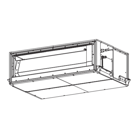
Page 108: Exploded Views And Price List Of Parts
15. EXPLODED VIEWS AND PARTS LIST 15-1. Indoor unit - 108 -... - Page 109 Model name Location MMD-UP Part No. Description 0721HFP-UL 0961HFP-UL 1201HFP-UL 43T39375 FLANGE, UPPER 43T39377 FLANGE, SIDE 43T39376 FLANGE, LOWER 43T44694 REFRIGERATION CYCLE ASSY 43T58332 REACTOR 43T21530 MOTOR, FAN 43T20345 FAN, MULTI BLADE, RIGHT 43T20346 FAN, MULTI BLADE, LEFT 43T22346 CASE, FAN, RIGHT 43T22347 CASE, FAN, LEFT 43T70322...
- Page 110 15-2. Electric Parts (L1) (L2) FOR INTER-UNIT FOR REMOTE CONTROL 1117875001 Model name Location MMD-UP Part No. Description 0721HFP-UL 0961HFP-UL 1201HFP-UL 43150440 TC-SENSOR 43T50476 SERVICE-SENSOR 43T50477 TC-SENSOR (TC1) 43T60458 SERV-TERMINAL 43T60362 TERMINAL 43TN9867 PC BOARD ASSY (MCC-1643) 43T6V670 PC BOARD ASSY 43T6V671 PC BOARD ASSY 43T50345...
- Page 111 144/9 MOO 5, BANGKADI INDUSTRIAL PARK, TIVANON ROAD, TAMBOL BANGKADI, AMPHUR MUANG, PATHUMTHANI 12000, THAILAND.